EP1672225A2 - Assemblage de vannes et méthode de contrôle d'un consommateur hydraulique à double effet - Google Patents
Assemblage de vannes et méthode de contrôle d'un consommateur hydraulique à double effet Download PDFInfo
- Publication number
- EP1672225A2 EP1672225A2 EP05110768A EP05110768A EP1672225A2 EP 1672225 A2 EP1672225 A2 EP 1672225A2 EP 05110768 A EP05110768 A EP 05110768A EP 05110768 A EP05110768 A EP 05110768A EP 1672225 A2 EP1672225 A2 EP 1672225A2
- Authority
- EP
- European Patent Office
- Prior art keywords
- pressure
- control
- valve
- consumer
- compensator
- Prior art date
- Legal status (The legal status is an assumption and is not a legal conclusion. Google has not performed a legal analysis and makes no representation as to the accuracy of the status listed.)
- Granted
Links
Images

Classifications
-
- F—MECHANICAL ENGINEERING; LIGHTING; HEATING; WEAPONS; BLASTING
- F15—FLUID-PRESSURE ACTUATORS; HYDRAULICS OR PNEUMATICS IN GENERAL
- F15B—SYSTEMS ACTING BY MEANS OF FLUIDS IN GENERAL; FLUID-PRESSURE ACTUATORS, e.g. SERVOMOTORS; DETAILS OF FLUID-PRESSURE SYSTEMS, NOT OTHERWISE PROVIDED FOR
- F15B11/00—Servomotor systems without provision for follow-up action; Circuits therefor
- F15B11/02—Systems essentially incorporating special features for controlling the speed or actuating force of an output member
- F15B11/04—Systems essentially incorporating special features for controlling the speed or actuating force of an output member for controlling the speed
- F15B11/05—Systems essentially incorporating special features for controlling the speed or actuating force of an output member for controlling the speed specially adapted to maintain constant speed, e.g. pressure-compensated, load-responsive
-
- F—MECHANICAL ENGINEERING; LIGHTING; HEATING; WEAPONS; BLASTING
- F15—FLUID-PRESSURE ACTUATORS; HYDRAULICS OR PNEUMATICS IN GENERAL
- F15B—SYSTEMS ACTING BY MEANS OF FLUIDS IN GENERAL; FLUID-PRESSURE ACTUATORS, e.g. SERVOMOTORS; DETAILS OF FLUID-PRESSURE SYSTEMS, NOT OTHERWISE PROVIDED FOR
- F15B11/00—Servomotor systems without provision for follow-up action; Circuits therefor
- F15B11/16—Servomotor systems without provision for follow-up action; Circuits therefor with two or more servomotors
- F15B11/161—Servomotor systems without provision for follow-up action; Circuits therefor with two or more servomotors with sensing of servomotor demand or load
- F15B11/165—Servomotor systems without provision for follow-up action; Circuits therefor with two or more servomotors with sensing of servomotor demand or load for adjusting the pump output or bypass in response to demand
-
- F—MECHANICAL ENGINEERING; LIGHTING; HEATING; WEAPONS; BLASTING
- F15—FLUID-PRESSURE ACTUATORS; HYDRAULICS OR PNEUMATICS IN GENERAL
- F15B—SYSTEMS ACTING BY MEANS OF FLUIDS IN GENERAL; FLUID-PRESSURE ACTUATORS, e.g. SERVOMOTORS; DETAILS OF FLUID-PRESSURE SYSTEMS, NOT OTHERWISE PROVIDED FOR
- F15B2211/00—Circuits for servomotor systems
- F15B2211/20—Fluid pressure source, e.g. accumulator or variable axial piston pump
- F15B2211/205—Systems with pumps
- F15B2211/2053—Type of pump
- F15B2211/20546—Type of pump variable capacity
-
- F—MECHANICAL ENGINEERING; LIGHTING; HEATING; WEAPONS; BLASTING
- F15—FLUID-PRESSURE ACTUATORS; HYDRAULICS OR PNEUMATICS IN GENERAL
- F15B—SYSTEMS ACTING BY MEANS OF FLUIDS IN GENERAL; FLUID-PRESSURE ACTUATORS, e.g. SERVOMOTORS; DETAILS OF FLUID-PRESSURE SYSTEMS, NOT OTHERWISE PROVIDED FOR
- F15B2211/00—Circuits for servomotor systems
- F15B2211/30—Directional control
- F15B2211/305—Directional control characterised by the type of valves
- F15B2211/30525—Directional control valves, e.g. 4/3-directional control valve
- F15B2211/3053—In combination with a pressure compensating valve
- F15B2211/30535—In combination with a pressure compensating valve the pressure compensating valve is arranged between pressure source and directional control valve
-
- F—MECHANICAL ENGINEERING; LIGHTING; HEATING; WEAPONS; BLASTING
- F15—FLUID-PRESSURE ACTUATORS; HYDRAULICS OR PNEUMATICS IN GENERAL
- F15B—SYSTEMS ACTING BY MEANS OF FLUIDS IN GENERAL; FLUID-PRESSURE ACTUATORS, e.g. SERVOMOTORS; DETAILS OF FLUID-PRESSURE SYSTEMS, NOT OTHERWISE PROVIDED FOR
- F15B2211/00—Circuits for servomotor systems
- F15B2211/30—Directional control
- F15B2211/31—Directional control characterised by the positions of the valve element
- F15B2211/3105—Neutral or centre positions
- F15B2211/3111—Neutral or centre positions the pump port being closed in the centre position, e.g. so-called closed centre
-
- F—MECHANICAL ENGINEERING; LIGHTING; HEATING; WEAPONS; BLASTING
- F15—FLUID-PRESSURE ACTUATORS; HYDRAULICS OR PNEUMATICS IN GENERAL
- F15B—SYSTEMS ACTING BY MEANS OF FLUIDS IN GENERAL; FLUID-PRESSURE ACTUATORS, e.g. SERVOMOTORS; DETAILS OF FLUID-PRESSURE SYSTEMS, NOT OTHERWISE PROVIDED FOR
- F15B2211/00—Circuits for servomotor systems
- F15B2211/30—Directional control
- F15B2211/31—Directional control characterised by the positions of the valve element
- F15B2211/3122—Special positions other than the pump port being connected to working ports or the working ports being connected to the return line
- F15B2211/3127—Floating position connecting the working ports and the return line
-
- F—MECHANICAL ENGINEERING; LIGHTING; HEATING; WEAPONS; BLASTING
- F15—FLUID-PRESSURE ACTUATORS; HYDRAULICS OR PNEUMATICS IN GENERAL
- F15B—SYSTEMS ACTING BY MEANS OF FLUIDS IN GENERAL; FLUID-PRESSURE ACTUATORS, e.g. SERVOMOTORS; DETAILS OF FLUID-PRESSURE SYSTEMS, NOT OTHERWISE PROVIDED FOR
- F15B2211/00—Circuits for servomotor systems
- F15B2211/30—Directional control
- F15B2211/315—Directional control characterised by the connections of the valve or valves in the circuit
- F15B2211/3157—Directional control characterised by the connections of the valve or valves in the circuit being connected to a pressure source, an output member and a return line
- F15B2211/31576—Directional control characterised by the connections of the valve or valves in the circuit being connected to a pressure source, an output member and a return line having a single pressure source and a single output member
-
- F—MECHANICAL ENGINEERING; LIGHTING; HEATING; WEAPONS; BLASTING
- F15—FLUID-PRESSURE ACTUATORS; HYDRAULICS OR PNEUMATICS IN GENERAL
- F15B—SYSTEMS ACTING BY MEANS OF FLUIDS IN GENERAL; FLUID-PRESSURE ACTUATORS, e.g. SERVOMOTORS; DETAILS OF FLUID-PRESSURE SYSTEMS, NOT OTHERWISE PROVIDED FOR
- F15B2211/00—Circuits for servomotor systems
- F15B2211/30—Directional control
- F15B2211/32—Directional control characterised by the type of actuation
- F15B2211/321—Directional control characterised by the type of actuation mechanically
- F15B2211/322—Directional control characterised by the type of actuation mechanically actuated by biasing means, e.g. spring-actuated
- F15B2211/323—Directional control characterised by the type of actuation mechanically actuated by biasing means, e.g. spring-actuated the biasing means being adjustable
-
- F—MECHANICAL ENGINEERING; LIGHTING; HEATING; WEAPONS; BLASTING
- F15—FLUID-PRESSURE ACTUATORS; HYDRAULICS OR PNEUMATICS IN GENERAL
- F15B—SYSTEMS ACTING BY MEANS OF FLUIDS IN GENERAL; FLUID-PRESSURE ACTUATORS, e.g. SERVOMOTORS; DETAILS OF FLUID-PRESSURE SYSTEMS, NOT OTHERWISE PROVIDED FOR
- F15B2211/00—Circuits for servomotor systems
- F15B2211/30—Directional control
- F15B2211/32—Directional control characterised by the type of actuation
- F15B2211/327—Directional control characterised by the type of actuation electrically or electronically
-
- F—MECHANICAL ENGINEERING; LIGHTING; HEATING; WEAPONS; BLASTING
- F15—FLUID-PRESSURE ACTUATORS; HYDRAULICS OR PNEUMATICS IN GENERAL
- F15B—SYSTEMS ACTING BY MEANS OF FLUIDS IN GENERAL; FLUID-PRESSURE ACTUATORS, e.g. SERVOMOTORS; DETAILS OF FLUID-PRESSURE SYSTEMS, NOT OTHERWISE PROVIDED FOR
- F15B2211/00—Circuits for servomotor systems
- F15B2211/40—Flow control
- F15B2211/41—Flow control characterised by the positions of the valve element
- F15B2211/413—Flow control characterised by the positions of the valve element the positions being continuously variable, e.g. as realised by proportional valves
-
- F—MECHANICAL ENGINEERING; LIGHTING; HEATING; WEAPONS; BLASTING
- F15—FLUID-PRESSURE ACTUATORS; HYDRAULICS OR PNEUMATICS IN GENERAL
- F15B—SYSTEMS ACTING BY MEANS OF FLUIDS IN GENERAL; FLUID-PRESSURE ACTUATORS, e.g. SERVOMOTORS; DETAILS OF FLUID-PRESSURE SYSTEMS, NOT OTHERWISE PROVIDED FOR
- F15B2211/00—Circuits for servomotor systems
- F15B2211/40—Flow control
- F15B2211/415—Flow control characterised by the connections of the flow control means in the circuit
- F15B2211/41527—Flow control characterised by the connections of the flow control means in the circuit being connected to an output member and a directional control valve
-
- F—MECHANICAL ENGINEERING; LIGHTING; HEATING; WEAPONS; BLASTING
- F15—FLUID-PRESSURE ACTUATORS; HYDRAULICS OR PNEUMATICS IN GENERAL
- F15B—SYSTEMS ACTING BY MEANS OF FLUIDS IN GENERAL; FLUID-PRESSURE ACTUATORS, e.g. SERVOMOTORS; DETAILS OF FLUID-PRESSURE SYSTEMS, NOT OTHERWISE PROVIDED FOR
- F15B2211/00—Circuits for servomotor systems
- F15B2211/40—Flow control
- F15B2211/42—Flow control characterised by the type of actuation
- F15B2211/428—Flow control characterised by the type of actuation actuated by fluid pressure
-
- F—MECHANICAL ENGINEERING; LIGHTING; HEATING; WEAPONS; BLASTING
- F15—FLUID-PRESSURE ACTUATORS; HYDRAULICS OR PNEUMATICS IN GENERAL
- F15B—SYSTEMS ACTING BY MEANS OF FLUIDS IN GENERAL; FLUID-PRESSURE ACTUATORS, e.g. SERVOMOTORS; DETAILS OF FLUID-PRESSURE SYSTEMS, NOT OTHERWISE PROVIDED FOR
- F15B2211/00—Circuits for servomotor systems
- F15B2211/40—Flow control
- F15B2211/46—Control of flow in the return line, i.e. meter-out control
-
- F—MECHANICAL ENGINEERING; LIGHTING; HEATING; WEAPONS; BLASTING
- F15—FLUID-PRESSURE ACTUATORS; HYDRAULICS OR PNEUMATICS IN GENERAL
- F15B—SYSTEMS ACTING BY MEANS OF FLUIDS IN GENERAL; FLUID-PRESSURE ACTUATORS, e.g. SERVOMOTORS; DETAILS OF FLUID-PRESSURE SYSTEMS, NOT OTHERWISE PROVIDED FOR
- F15B2211/00—Circuits for servomotor systems
- F15B2211/50—Pressure control
- F15B2211/505—Pressure control characterised by the type of pressure control means
- F15B2211/50509—Pressure control characterised by the type of pressure control means the pressure control means controlling a pressure upstream of the pressure control means
- F15B2211/50518—Pressure control characterised by the type of pressure control means the pressure control means controlling a pressure upstream of the pressure control means using pressure relief valves
- F15B2211/50527—Pressure control characterised by the type of pressure control means the pressure control means controlling a pressure upstream of the pressure control means using pressure relief valves using cross-pressure relief valves
-
- F—MECHANICAL ENGINEERING; LIGHTING; HEATING; WEAPONS; BLASTING
- F15—FLUID-PRESSURE ACTUATORS; HYDRAULICS OR PNEUMATICS IN GENERAL
- F15B—SYSTEMS ACTING BY MEANS OF FLUIDS IN GENERAL; FLUID-PRESSURE ACTUATORS, e.g. SERVOMOTORS; DETAILS OF FLUID-PRESSURE SYSTEMS, NOT OTHERWISE PROVIDED FOR
- F15B2211/00—Circuits for servomotor systems
- F15B2211/50—Pressure control
- F15B2211/505—Pressure control characterised by the type of pressure control means
- F15B2211/50563—Pressure control characterised by the type of pressure control means the pressure control means controlling a differential pressure
- F15B2211/50572—Pressure control characterised by the type of pressure control means the pressure control means controlling a differential pressure using a pressure compensating valve for controlling the pressure difference across a flow control valve
-
- F—MECHANICAL ENGINEERING; LIGHTING; HEATING; WEAPONS; BLASTING
- F15—FLUID-PRESSURE ACTUATORS; HYDRAULICS OR PNEUMATICS IN GENERAL
- F15B—SYSTEMS ACTING BY MEANS OF FLUIDS IN GENERAL; FLUID-PRESSURE ACTUATORS, e.g. SERVOMOTORS; DETAILS OF FLUID-PRESSURE SYSTEMS, NOT OTHERWISE PROVIDED FOR
- F15B2211/00—Circuits for servomotor systems
- F15B2211/50—Pressure control
- F15B2211/515—Pressure control characterised by the connections of the pressure control means in the circuit
- F15B2211/5159—Pressure control characterised by the connections of the pressure control means in the circuit being connected to an output member and a return line
Definitions
- the invention relates to a valve arrangement and a method for controlling a double-acting consumer according to the preamble of patent claim 1 and of independent patent claim 8.
- valve assemblies are used, for example, to control the work functions of mobile implements, such as tractors or excavators.
- the control of these hydraulic functions is usually via a very compact control block, in which all the essential directional and control valves are combined into one unit.
- a control block is described for example in the catalog 1 987 760 507 (electronic hydraulic hitch control for tractors) of the applicant. Further details can be found in the post-published application with the official file number 10 2004 033 315.7.
- Modern tractors are designed for example with a Heckhubwerk and a front lifting, the lifting cylinder can be acted upon by the control pressure with pressure medium, which is funded by a pump which is controlled so that in a pump line to a certain pressure difference across the load pressure of the consumer lying pump pressure prevails.
- Both the rear and the front lift are designed to double acting in modern tractors, each of the consumers are associated with electro-hydraulically actuated directional valves, which are controlled by an electric control unit of the mobile vehicle.
- the setpoints are for example via a front panel or a rear panel set inside the cabin.
- the usually double-acting consumers can also be operated in single-acting mode, in which case, for example, a pressure chamber of the consumer is relieved at very low pressure to the tank, so that the consumer behaves like a single-acting consumer and, for example, lifting the hoist by supplying the Pressure medium to the other pressure chamber takes place while the lowering takes place solely by the weight of the load, the first-mentioned pressure chamber is relieved.
- tractors usually a rear push button or a front button is provided, which are arranged on the rear or front of the tractor and make it possible to operate the hoists from the outside - for example, for coupling a working device.
- the invention has for its object to provide a valve assembly and a method for driving a double-acting consumer, in which the risk of undersupply is reduced.
- the valve arrangement for controlling a double-acting consumer has a variable one Metering orifice, which is associated with an individual pressure compensator, via which the pressure drop across the metering orifice can be kept constant independent of the load pressure.
- this individual pressure compensator can be brought into a blocking position under certain operating conditions, for example when lowering a load, so that despite the controlled metering orifice of the pressure fluid flow path is shut off from a pressure medium source to the pressurized medium pressure chamber of the consumer. That is, according to the invention can be shut off depending on the operating condition of the pressure medium flow to the consumer, so that the system does not reach the saturation and the risk of undersupply of consumers is reduced.
- the individual pressure compensator is associated with a pilot valve via which an effective in the closing direction control surface of a control piston of the individual pressure compensator with the pressure of a pressure medium source of the system, usually a LS pump is acted upon, so that the control piston regardless of the on him acting load pressure can be brought into its blocking position.
- the pilot valve only has to pass relatively small control oil volume flows, it can be designed to be relatively small - with this small pilot valve, however, a comparatively large pressure medium volume flow can be switched on or off.
- the solution according to the invention works particularly advantageous, for example, when the consumer is operated in a single action and - for example, when lowering the consumer - the increasing pressure chamber is separated by the inventive valve assembly and the inventive method of the pressure medium supply.
- the pilot valve is preferably designed as an electrically actuated 2-way switching valve that shuts off a connection between the pressure chamber of the individual pressure compensator and a pump line in its spring-biased basic position and opens this connection in its switching position.
- a nozzle is arranged in this.
- This nozzle can be dispensed with if the pilot valve is designed as a 3/2-way switching valve that shuts off a connection between the pressure chamber and the pump line in its spring-biased basic position and opens the aforementioned control line and shuts off this control line in its switching position and the pressure chamber of the individual pressure compensator subjected to the pressure in the pump line.
- the pilot valve is designed as a 3/2-way switching valve that shuts off a connection between the pressure chamber and the pump line in its spring-biased basic position and opens the aforementioned control line and shuts off this control line in its switching position and the pressure chamber of the individual pressure compensator subjected to the pressure in the pump line.
- the invention with depending on the operating state in a locking position can be brought individual pressure balance can be used both in LUDV systems as well as upstream or downstream LS individual pressure compensator.
- a LUDV system is disclosed in which a LUDV individual pressure compensator is movable when a predetermined load pressure is exceeded in a blocking position, this maximum load pressure is selected so that the associated consumer can be supplied with a sufficient amount of pressure medium.
- the invention operates according to a completely different concept, according to which the pressure medium supply to a consumer depending on the operating state is completely shut off - this shut-off is independent of the load applied to the load.
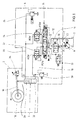
- Modern tractors are designed with at least one hoist 2, which has a double-acting lifting cylinder 6, the pressure chambers are acted upon via a Hubtechniksventilan Aunt 8 invention with pressure medium or connected to a tank, which is composed with the directional valves for controlling the other consumers of the tractor to a control block ,
- a Heckhubwerk 2 of FIG. 1 can be used in different operating conditions.
- the work area “carry” the Heckhubwerk and, where appropriate, the attached implement is either lifted off the ground or it is worn in contact with the ground with a predetermined support force.
- This work area occurs, for example, when plowing or when cultivating.
- the working area "pressing” the Heckhubwerk 2 is driven so that a force acting in the direction of the ground pressure force is applied.
- a setting is, for example, move in active plow or required by a packer.
- a load-free intermediate position in which the Heckhubwerk 2 is not acted upon by a force, this is due to its own weight on the ground.
- Such a load-free intermediate position is - as described below - adjusted by adjusting the Hubtechniksventilan angel 4 in a floating position.
- the Hubtechniksventilan Aunt executed in disc design 4 has a pressure port P, a tank port T, a LS port LS and two working ports A, B.
- the pressure port P is connected via a pump line with a variable displacement pump 8, the discharge pressure in response to the highest, to the Consumers of the tractor is applied load pressure. This load pressure is tapped at the LS port.
- An LS control in which the flow rate of the pump depending is set by the highest load pressure, but is not a prerequisite for the system according to the invention.
- the pressure port P is connected via an inlet channel 10 to an input port P 'of an individual pressure compensator 12 whose output port A' is connected to an input port P "of a continuously variable directional control valve 14.
- Its return port R is connected via a return passage 16 to the tank port T of the Hubtechniksventilanowski note 4.
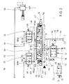
- the directional control valve 14 has two working ports A “and B" (see Fig. 2), which are connected via working channels 18, 20 with the two working ports A, B of the Hubtechniksventilan accent 4.
- the individual pressure compensator 12 is associated with a pilot valve 13 through which the Individual pressure compensator 12 is switchable in certain operating conditions in their blocking position.
- each working channel 18, 20 is a respective sink module 22, 24 is provided, which serves in a basic position as a pilot-operated check valve for leak oil-free clamping of the lifting cylinder 6 of the Heckhubwerks 2 and controls in a control position flowing back from the lifting cylinder 6 pressure medium flow in the sense of a flow control.
- the working channel 20 can be connected to the tank connection T downstream of the sink module 24 via a pilot-controlled, proportionally adjustable pressure-limiting valve 26.
- the pressure in the other working channel 18 is limited by a secondary pressure relief valve 28.
- the lifting cylinder 6 is - as mentioned - designed double-acting, with an effective in the direction of "lowering" annular space 30 with the working port B and in the direction of "lifting" effective pressure chamber 32 is connected to the working port A of Hubtechniksventilanssen 4.
- a pivotally mounted on a lifting shaft 34 arm 36 and other coupling elements are actuated, where, for example, an attachment, such as a seed drill or a plow 38 is grown.
- a pressure compensator piston of the pressure compensator 12 is acted upon by a pressure compensator spring 40 and by the pressure tapped in the opening direction via a channel 42 from a load-signaling duct 44 connected to the LS connection and by the pressure in a control duct 46 in the closing direction, which is between the pressure compensator 12 and the pressure compensator
- Directional valve 14 branches off from the inlet channel 10. From the control channel 46 branches off a pilot control line 70, which is guided to the output terminal of the pilot valve 13, whose input terminal is connected via a pilot pressure channel 72 to the upstream of the pressure compensator 12 located part of the inlet channel 10.
- the pilot valve 13 is biased via a pilot valve spring 74 in its illustrated blocking position in which the connection between the pilot pressure passage 72 and the pilot control line 70 is shut off.
- the LS channel 44 leads to a control connection LS '' of the directional control valve 14.
- This has two more control terminals X, whose output side control terminals XA and XB are assigned.
- the operation of the directional control valve 14 via a pilot valve assembly, which is formed in the illustration of Figure 2 by two electro-hydraulic pilot elements 45, 47.
- the triangle 49 indicates the control oil supply, for example a control oil pump, to these pilot control elements 47, 45.
- control oil can each be fed to a control chamber of the directional valve 14 until a valve slide 50 assumes a working position. This is recorded via a transducer. As soon as the desired position is reported by this, the pilot element 47, 45 is brought back into its neutral position.
- valve spool 50 The position of the valve spool 50 is maintained regulated by the pilot elements 47, 45 are driven in accordance with the signal of the position transducer. These are connected via control lines 52 and 54 with the pilot oil supply 49.
- the valve spool 50 is biased via a Zentrierfederan Aunt 56 in its illustrated basic position (0), in which the LS channel 44 is connected to the tank channel 16 and all other aforementioned connections are shut off.
- valve body of the two sink modules 22, 24 are each acted upon by a spring 58 and by the individual load pressure tapped at the outlet A '' or B '' via pressure compensator ducts 60, 62 downstream of the directional control valve 14 into its basic position (a) in which the Lowering modules 22, 24 act as check valves, which allow a flow of pressure medium to the terminals A, B.
- the valve body of the sink modules 22, 24 respectively acted upon by the voltage applied to the terminal XA and XB control pressure, which is tapped via a Entsperrkanal 64, 66.
- This control pressure can correspond, for example, to the inlet pressure of the pilot control elements 45, 47.
- the valve spool 50 of the directional control valve 14 is displaced via the pilot control element 45 into one of its positions marked with (b). In this case, a metering orifice is opened, which is connected downstream of the individual pressure compensator 12. Depending on the orifice size, the pressure compensator 12 adjusts to a control position in which the pressure drop across the orifice plate is kept constant and thus a pressure-medium-independent pressure medium volume flow is set.
- This pressure medium volume flow is in the control positions indicated by (b) via the pressure compensator 12, the pressure port P '' and the output port A '' of the directional control valve 14 to the input port PDW of the sink module 22 and via its output port ADW to the working port A of the Hubtechniksventilan Aunt 4 and from there guided in the bottom-side pressure chamber 32 - the lifting cylinder 6 extends.
- the displaced from the annulus 30 pressure fluid flows through the working port B of the Hubtechniksventilan angel 4, the working channel 20, the output port BDW and the input terminal PDW of the sink module 24 to the terminal B '' of the directional control valve 14 and from there via the return port R, the tank channel 16 and the tank port T back to the tank.
- the directional control valve 14 For pressing an implement supported by the hoist, the directional control valve 14 is displaced into one of its control positions marked with (a), so that the pressure medium is supplied via the sink module 24 in its non-return function to the annular space 30, while the pressure medium flowing out of the bottom pressure chamber 32 via the unlocked drain module 22 and the directional control valve 14 flows towards the tank.
- the unlocking takes place via the control pressure, which is guided via the control terminals X, XA of the directional control valve 14 and the Entsperrkanal 64 to the effective opening direction in the control surface of the sink module 22.
- the directional control valve 14 is moved into its floating position (end position c), in which both lowering modules 22, 24 are unlocked and moved into their through position marked with (b) and the working connections A, B and the control connection LS are connected to the tank connection T. and the input terminal P "is shut off.
- the maximum pressure in the working channel 20 is limited by a suitable adjustment of the proportionally adjustable pressure relief valve 26 to a value of, for example, between 0 to 250 bar.
- the pressure in the working channel 18 is limited to a maximum pressure set below the pump pressure.
- the construction of such secondary pressure relief valves is known, so that further explanations are unnecessary.
- the construction of the pilot operated proportionally adjustable pressure relief valve 26 is known per se - a piston of the pressure relief valve 26 is loaded via a weak compression spring and by the pressure in the spring chamber against a valve seat in a closed position. The pressure in the spring chamber is limited by the force applied to a closing cone by means of a proportional magnet.
- the control of the proportional solenoid via the control unit 16.
- pressure sensors via which the pressures in the working channels 28, 30, the pressure at the pressure port P, the load pressure and other pressures can be detected.
- the pressure limiting valve 26 is set to a minimum value, for example 5 to 8 bar, so that a minimum pressure is set at the working connection B and thus in the annular space 30 of the lifting cylinder 6.
- EHR electrohydraulic hoist control
- the directional control valve 14 after lowering not in its neutral position (0) as in the double-acting function but in the floating position (c) adjusted - the hoist can move then adjust to any unevenness of the soil.
- the set behavior corresponds to that of conventional single-acting lifting gear valves.
- an undersupply can be avoided according to the invention by the pilot valve 13 being switched to its passage position by energizing the switching magnet 78.
- the control piston of the pressure compensator 12 is brought into its closed position by the pump pressure picked off via the pilot pressure duct 72 and the pilot control line 70, so that the pressure medium connection to the enlarging annular space 30 is shut off. That is, it is no pressure medium in the increasing annular space 30 refilled and the Heckhubwerk 2 remains in contact with the ground simply stand and thus forms the previously known single-acting hoisting behavior almost completely.
- the pump pressure is sufficiently high in all operating conditions to close the individual pressure compensator 12 safely. Even in the case that there is already a shortage of supply prior to actuation of the pilot valve 13, ie, the pump pressure and the consumer pressure are almost the same, a pressure medium volume flow will set on the rear lift due to the low load (pulling consumer). This leads to a pressure drop across the directional valve slide control edge and thus to a sufficiently large pressure difference for closing the pressure compensator 12th
- the switching on of the pump pressure according to the invention and the resulting shutting off of the pressure medium supply of a consumer can take place in all operating states in which a cylinder side does not necessarily have to be refilled. Such operating conditions occur when no pressure medium is needed on the sink side of the hoist cylinder and there is a risk that another consumer will stop due to undersupply.
- the switching on of the pump pressure according to the invention via the pilot valve 13 can thus take place during lowering of the hoist in its control function (that is not in the transport position in which a vibration damping takes place or when the lowering is controlled via a rear switch) and the above-described single-acting operation.
- the concept according to the invention is also not used if a "cut" is active in the operating state "lowering", as described in DE 10 2004 033 315.7. At this cut a force applied in the lowering direction is limited to a maximum value.
- FIG. 3 shows an exemplary embodiment in which the nozzle 76 can be dispensed with.
- the pilot valve 13 is designed as a 3/2-way switching valve, wherein the pilot pressure channel 72 is connected to a first input terminal and the control channel 46 to a second input terminal.
- the pilot valve 13 In its spring-biased basic position, the pilot valve 13 according to FIG. 3 connects the control channel 46 with the pilot control line 70, which extends from the outlet connection of the pilot valve 13 to the pressure chamber of the pressure compensator 12 which is effective in the closing direction.
- the pilot pressure passage 72 is shut off - thus acts on the pressure compensator 12 in the closing direction of the pressure in the area between the directional control valve 14 and the pressure compensator 12.
- the pilot valve 13 is on the Switching solenoid 78 is switched to its switching position in which the control channel 46 is shut off and the pilot control line 70 is connected to the pilot pressure channel 72.
- the control piston of the pressure compensator 42 is moved by the pump pressure in its closed position - the refilling of the increasing cylinder side does not take place and the "saved" pressure medium volume flow can be used to supply other consumers.
- a valve arrangement and a method for controlling a double-acting consumer in particular a lifting mechanism of a mobile working device, wherein a consumer an adjustable metering orifice and an individual pressure compensator is assigned, via which the pressure difference across the metering orifice can be kept constant constant load pressure.
- the individual pressure compensator can be in predetermined operating states Switch from the load pressure in a blocking position, so that the pressure medium supply is shut off to the consumer, although the metering orifice is opened further.
Landscapes
- Engineering & Computer Science (AREA)
- Physics & Mathematics (AREA)
- Fluid Mechanics (AREA)
- Mechanical Engineering (AREA)
- General Engineering & Computer Science (AREA)
- Fluid-Pressure Circuits (AREA)
- Fluid-Driven Valves (AREA)
- Control Of Metal Rolling (AREA)
Applications Claiming Priority (2)
| Application Number | Priority Date | Filing Date | Title |
|---|---|---|---|
| DE102004062348 | 2004-12-20 | ||
| DE102005005314A DE102005005314A1 (de) | 2004-12-20 | 2005-02-04 | Ventilanordnung und Verfahren zur Ansteuerung eines doppeltwirkenden Verbrauchers |
Publications (3)
| Publication Number | Publication Date |
|---|---|
| EP1672225A2 true EP1672225A2 (fr) | 2006-06-21 |
| EP1672225A3 EP1672225A3 (fr) | 2009-06-03 |
| EP1672225B1 EP1672225B1 (fr) | 2011-07-27 |
Family
ID=35851069
Family Applications (1)
| Application Number | Title | Priority Date | Filing Date |
|---|---|---|---|
| EP05110768A Expired - Lifetime EP1672225B1 (fr) | 2004-12-20 | 2005-11-15 | Assemblage de vannes et méthode de contrôle d'un consommateur hydraulique à double effet |
Country Status (3)
| Country | Link |
|---|---|
| EP (1) | EP1672225B1 (fr) |
| AT (1) | ATE518063T1 (fr) |
| DE (1) | DE102005005314A1 (fr) |
Cited By (9)
| Publication number | Priority date | Publication date | Assignee | Title |
|---|---|---|---|---|
| EP2064933A1 (fr) * | 2007-11-28 | 2009-06-03 | Robert Bosch GmbH | Entraînement de roulement pour appareils de travail |
| WO2012123056A1 (fr) * | 2011-03-12 | 2012-09-20 | Robert Bosch Gmbh | Entraînement auxiliaire pour engins de travail |
| US20180153101A1 (en) * | 2016-06-21 | 2018-06-07 | Macdon Industries Ltd. | Crop Machine with an Electronically Controlled Hydraulic Cylinder Flotation System |
| DE102017219942A1 (de) | 2017-11-09 | 2019-05-09 | Robert Bosch Gmbh | Ventilanordung für Hubwerkssteuerung mit einer Druckregelvorrichtung |
| DE102018221288A1 (de) | 2018-01-04 | 2019-07-04 | Robert Bosch Gmbh | Ventilanordnung, Arbeitsmaschine und Verfahren zum Steuern einer Ventilanordnung |
| US10820470B2 (en) | 2018-08-24 | 2020-11-03 | Cnh Industrial America Llc | Hydraulic system for an agricultural implement incorporating implement-based hydraulic load sensing |
| US10820471B2 (en) | 2018-08-24 | 2020-11-03 | Cnh Industrial America Llc | Hydraulic system for an agricultural implement incorporating an implement-based override valve |
| US20220242295A1 (en) * | 2021-02-01 | 2022-08-04 | Caterpillar Inc. | Closed center hoist valve with snubbing |
| US20250314046A1 (en) * | 2024-04-09 | 2025-10-09 | Cnh Industrial America Llc | System and method for controlling hydraulic fluid flow within a work vehicle |
Families Citing this family (10)
| Publication number | Priority date | Publication date | Assignee | Title |
|---|---|---|---|---|
| DE102006004423B4 (de) | 2006-01-31 | 2018-08-02 | Robert Bosch Gmbh | Ventilanordnung zur Ansteuerung eines Hubwerkes oder Anbaugerätes sowie Verfahren zur Ansteuerung dieser |
| DE102007030133A1 (de) * | 2007-06-29 | 2009-01-02 | Robert Bosch Gmbh | Ventilanordnung |
| DE102007040345A1 (de) | 2007-07-18 | 2009-01-22 | Robert Bosch Gmbh | Verfahren zum Ansteuern eines Hubwerks und Hubwerk |
| DE102007040344A1 (de) | 2007-07-19 | 2009-01-22 | Robert Bosch Gmbh | Hubwerk und Verfahren zum Ansteuern eines derartigen Hubwerks |
| DE102007040877A1 (de) | 2007-08-29 | 2009-03-05 | Robert Bosch Gmbh | Hubwerk und Verfahren zum Ansteuern eines Hubwerkes |
| EP2466153B1 (fr) | 2010-12-17 | 2013-08-14 | HAWE Hydraulik SE | Dispositif de commande hydroélectrique |
| DE102011101553A1 (de) | 2011-05-14 | 2012-11-15 | Robert Bosch Gmbh | Hubwerk |
| EP2597209B1 (fr) | 2011-11-23 | 2016-03-16 | HAWE Hydraulik SE | Système de réglage d'un dispositif de levage hydro-électronique |
| EP2597210B1 (fr) | 2011-11-23 | 2016-03-16 | HAWE Hydraulik SE | Dispositif de commande hydroélectrique |
| DE102013207299B4 (de) * | 2013-04-23 | 2025-11-06 | Robert Bosch Gmbh | Hydraulisches Wegeventil für das Hubwerk eines landwirtschaftlichen Fahrzeugs |
Citations (2)
| Publication number | Priority date | Publication date | Assignee | Title |
|---|---|---|---|---|
| DE19831595A1 (de) | 1998-07-14 | 2000-01-20 | Mannesmann Rexroth Ag | Hydraulische Schaltung |
| DE102004033315A1 (de) | 2004-07-09 | 2006-02-09 | Bosch Rexroth Aktiengesellschaft | Hubwerksventilanordnung |
Family Cites Families (1)
| Publication number | Priority date | Publication date | Assignee | Title |
|---|---|---|---|---|
| US5186000A (en) * | 1988-05-10 | 1993-02-16 | Hitachi Construction Machinery Co., Ltd. | Hydraulic drive system for construction machines |
-
2005
- 2005-02-04 DE DE102005005314A patent/DE102005005314A1/de not_active Withdrawn
- 2005-11-15 AT AT05110768T patent/ATE518063T1/de active
- 2005-11-15 EP EP05110768A patent/EP1672225B1/fr not_active Expired - Lifetime
Patent Citations (2)
| Publication number | Priority date | Publication date | Assignee | Title |
|---|---|---|---|---|
| DE19831595A1 (de) | 1998-07-14 | 2000-01-20 | Mannesmann Rexroth Ag | Hydraulische Schaltung |
| DE102004033315A1 (de) | 2004-07-09 | 2006-02-09 | Bosch Rexroth Aktiengesellschaft | Hubwerksventilanordnung |
Cited By (14)
| Publication number | Priority date | Publication date | Assignee | Title |
|---|---|---|---|---|
| EP2064933A1 (fr) * | 2007-11-28 | 2009-06-03 | Robert Bosch GmbH | Entraînement de roulement pour appareils de travail |
| WO2012123056A1 (fr) * | 2011-03-12 | 2012-09-20 | Robert Bosch Gmbh | Entraînement auxiliaire pour engins de travail |
| CN103547812A (zh) * | 2011-03-12 | 2014-01-29 | 罗伯特·博世有限公司 | 用于做功器具的辅助驱动装置 |
| CN103547812B (zh) * | 2011-03-12 | 2016-11-09 | 罗伯特·博世有限公司 | 用于做功器具的辅助驱动装置 |
| US10624263B2 (en) * | 2016-06-21 | 2020-04-21 | Macdon Industries Ltd | Crop machine with an electronically controlled hydraulic cylinder flotation system |
| US20180153101A1 (en) * | 2016-06-21 | 2018-06-07 | Macdon Industries Ltd. | Crop Machine with an Electronically Controlled Hydraulic Cylinder Flotation System |
| DE102017219942A1 (de) | 2017-11-09 | 2019-05-09 | Robert Bosch Gmbh | Ventilanordung für Hubwerkssteuerung mit einer Druckregelvorrichtung |
| DE102018221288A1 (de) | 2018-01-04 | 2019-07-04 | Robert Bosch Gmbh | Ventilanordnung, Arbeitsmaschine und Verfahren zum Steuern einer Ventilanordnung |
| US10820470B2 (en) | 2018-08-24 | 2020-11-03 | Cnh Industrial America Llc | Hydraulic system for an agricultural implement incorporating implement-based hydraulic load sensing |
| US10820471B2 (en) | 2018-08-24 | 2020-11-03 | Cnh Industrial America Llc | Hydraulic system for an agricultural implement incorporating an implement-based override valve |
| US20220242295A1 (en) * | 2021-02-01 | 2022-08-04 | Caterpillar Inc. | Closed center hoist valve with snubbing |
| US11654815B2 (en) * | 2021-02-01 | 2023-05-23 | Caterpillar Inc. | Closed center hoist valve with snubbing |
| US20250314046A1 (en) * | 2024-04-09 | 2025-10-09 | Cnh Industrial America Llc | System and method for controlling hydraulic fluid flow within a work vehicle |
| US12523014B2 (en) * | 2024-04-09 | 2026-01-13 | Cnh Industrial America Llc | System and method for controlling hydraulic fluid flow within a work vehicle |
Also Published As
| Publication number | Publication date |
|---|---|
| ATE518063T1 (de) | 2011-08-15 |
| DE102005005314A1 (de) | 2006-06-22 |
| EP1672225A3 (fr) | 2009-06-03 |
| EP1672225B1 (fr) | 2011-07-27 |
Similar Documents
| Publication | Publication Date | Title |
|---|---|---|
| EP1766146B1 (fr) | Systeme de soupapes de mecanisme de levage | |
| EP1672225B1 (fr) | Assemblage de vannes et méthode de contrôle d'un consommateur hydraulique à double effet | |
| EP2031256B1 (fr) | Dispositif de levage et procédé de commande d'un dispositif de levage | |
| EP1450048B1 (fr) | Agencement de vanne | |
| DE102004050294B3 (de) | Hydraulische Ventilanordnung | |
| EP2449267B1 (fr) | Dispositif de soupape | |
| DE4106845C2 (fr) | ||
| EP2142808B1 (fr) | Ensemble de commande hydraulique | |
| CH700344B1 (de) | Steuervorrichtung für mindestens zwei hydraulische Antriebe. | |
| EP3940246A1 (fr) | Agencement de soupape et procédé pour commander un dispositif de levage ou un appareil porté | |
| EP2404493B1 (fr) | Dispositif de levage | |
| DE10340505B4 (de) | Ventilanordnung zur Steuerung eines Hydraulikantriebs | |
| DE102006004423B4 (de) | Ventilanordnung zur Ansteuerung eines Hubwerkes oder Anbaugerätes sowie Verfahren zur Ansteuerung dieser | |
| WO2016091528A1 (fr) | Agencement de soupapes hydraulique, bloc de soupapes hydraulique ayant un tel agencement de soupapes, et mécanisme d'entraînement hydraulique ayant un tel bloc de soupapes hydraulique | |
| DE3901207C2 (de) | Ventilanordnung für mehrere hydraulische Antriebe, insbesondere für die Antriebe eines Krans | |
| DE19548943B4 (de) | Ventilanordnung | |
| EP1766246B1 (fr) | Procede de commande d'un systeme a vannes pour dispositif de levage | |
| DE2800814A1 (de) | Hydraulische steuereinrichtung | |
| WO1999024720A1 (fr) | Circuit hydraulique | |
| DE3431103A1 (de) | Hydraulische steuereinrichtung | |
| EP3985264A1 (fr) | Agencement et procédé de commande d'un mécanisme de levage | |
| DE1027442B (de) | Kombinierte Steuerungseinrichtung fuer hydraulische Heber und Hilfsheber an Ackerschleppern |
Legal Events
| Date | Code | Title | Description |
|---|---|---|---|
| PUAI | Public reference made under article 153(3) epc to a published international application that has entered the european phase |
Free format text: ORIGINAL CODE: 0009012 |
|
| AK | Designated contracting states |
Kind code of ref document: A2 Designated state(s): AT BE BG CH CY CZ DE DK EE ES FI FR GB GR HU IE IS IT LI LT LU LV MC NL PL PT RO SE SI SK TR |
|
| AX | Request for extension of the european patent |
Extension state: AL BA HR MK YU |
|
| PUAL | Search report despatched |
Free format text: ORIGINAL CODE: 0009013 |
|
| AK | Designated contracting states |
Kind code of ref document: A3 Designated state(s): AT BE BG CH CY CZ DE DK EE ES FI FR GB GR HU IE IS IT LI LT LU LV MC NL PL PT RO SE SI SK TR |
|
| AX | Request for extension of the european patent |
Extension state: AL BA HR MK YU |
|
| 17P | Request for examination filed |
Effective date: 20091203 |
|
| AKX | Designation fees paid |
Designated state(s): AT BE BG CH CY CZ DE DK EE ES FI FR GB GR HU IE IS IT LI LT LU LV MC NL PL PT RO SE SI SK TR |
|
| GRAP | Despatch of communication of intention to grant a patent |
Free format text: ORIGINAL CODE: EPIDOSNIGR1 |
|
| GRAS | Grant fee paid |
Free format text: ORIGINAL CODE: EPIDOSNIGR3 |
|
| GRAA | (expected) grant |
Free format text: ORIGINAL CODE: 0009210 |
|
| AK | Designated contracting states |
Kind code of ref document: B1 Designated state(s): AT BE BG CH CY CZ DE DK EE ES FI FR GB GR HU IE IS IT LI LT LU LV MC NL PL PT RO SE SI SK TR |
|
| REG | Reference to a national code |
Ref country code: GB Ref legal event code: FG4D Free format text: NOT ENGLISH |
|
| REG | Reference to a national code |
Ref country code: CH Ref legal event code: EP |
|
| REG | Reference to a national code |
Ref country code: DE Ref legal event code: R096 Ref document number: 502005011669 Country of ref document: DE Effective date: 20110922 |
|
| REG | Reference to a national code |
Ref country code: NL Ref legal event code: VDEP Effective date: 20110727 |
|
| RIN2 | Information on inventor provided after grant (corrected) |
Inventor name: SOENKE JESSEN Inventor name: KEUPER, GERHARD, DR. Inventor name: STACHNIK, PETER, DR. Inventor name: KUNZ, REINER Inventor name: LOEDIGE, HEINRICH |
|
| PG25 | Lapsed in a contracting state [announced via postgrant information from national office to epo] |
Ref country code: PT Free format text: LAPSE BECAUSE OF FAILURE TO SUBMIT A TRANSLATION OF THE DESCRIPTION OR TO PAY THE FEE WITHIN THE PRESCRIBED TIME-LIMIT Effective date: 20111128 Ref country code: NL Free format text: LAPSE BECAUSE OF FAILURE TO SUBMIT A TRANSLATION OF THE DESCRIPTION OR TO PAY THE FEE WITHIN THE PRESCRIBED TIME-LIMIT Effective date: 20110727 Ref country code: FI Free format text: LAPSE BECAUSE OF FAILURE TO SUBMIT A TRANSLATION OF THE DESCRIPTION OR TO PAY THE FEE WITHIN THE PRESCRIBED TIME-LIMIT Effective date: 20110727 Ref country code: IS Free format text: LAPSE BECAUSE OF FAILURE TO SUBMIT A TRANSLATION OF THE DESCRIPTION OR TO PAY THE FEE WITHIN THE PRESCRIBED TIME-LIMIT Effective date: 20111127 Ref country code: SE Free format text: LAPSE BECAUSE OF FAILURE TO SUBMIT A TRANSLATION OF THE DESCRIPTION OR TO PAY THE FEE WITHIN THE PRESCRIBED TIME-LIMIT Effective date: 20110727 Ref country code: LT Free format text: LAPSE BECAUSE OF FAILURE TO SUBMIT A TRANSLATION OF THE DESCRIPTION OR TO PAY THE FEE WITHIN THE PRESCRIBED TIME-LIMIT Effective date: 20110727 |
|
| PG25 | Lapsed in a contracting state [announced via postgrant information from national office to epo] |
Ref country code: CY Free format text: LAPSE BECAUSE OF FAILURE TO SUBMIT A TRANSLATION OF THE DESCRIPTION OR TO PAY THE FEE WITHIN THE PRESCRIBED TIME-LIMIT Effective date: 20110727 Ref country code: GR Free format text: LAPSE BECAUSE OF FAILURE TO SUBMIT A TRANSLATION OF THE DESCRIPTION OR TO PAY THE FEE WITHIN THE PRESCRIBED TIME-LIMIT Effective date: 20111028 Ref country code: PL Free format text: LAPSE BECAUSE OF FAILURE TO SUBMIT A TRANSLATION OF THE DESCRIPTION OR TO PAY THE FEE WITHIN THE PRESCRIBED TIME-LIMIT Effective date: 20110727 Ref country code: LV Free format text: LAPSE BECAUSE OF FAILURE TO SUBMIT A TRANSLATION OF THE DESCRIPTION OR TO PAY THE FEE WITHIN THE PRESCRIBED TIME-LIMIT Effective date: 20110727 Ref country code: SI Free format text: LAPSE BECAUSE OF FAILURE TO SUBMIT A TRANSLATION OF THE DESCRIPTION OR TO PAY THE FEE WITHIN THE PRESCRIBED TIME-LIMIT Effective date: 20110727 |
|
| REG | Reference to a national code |
Ref country code: IE Ref legal event code: FD4D |
|
| PG25 | Lapsed in a contracting state [announced via postgrant information from national office to epo] |
Ref country code: SK Free format text: LAPSE BECAUSE OF FAILURE TO SUBMIT A TRANSLATION OF THE DESCRIPTION OR TO PAY THE FEE WITHIN THE PRESCRIBED TIME-LIMIT Effective date: 20110727 Ref country code: CZ Free format text: LAPSE BECAUSE OF FAILURE TO SUBMIT A TRANSLATION OF THE DESCRIPTION OR TO PAY THE FEE WITHIN THE PRESCRIBED TIME-LIMIT Effective date: 20110727 Ref country code: IE Free format text: LAPSE BECAUSE OF FAILURE TO SUBMIT A TRANSLATION OF THE DESCRIPTION OR TO PAY THE FEE WITHIN THE PRESCRIBED TIME-LIMIT Effective date: 20110727 |
|
| BERE | Be: lapsed |
Owner name: BOSCH REXROTH A.G. Effective date: 20111130 |
|
| PG25 | Lapsed in a contracting state [announced via postgrant information from national office to epo] |
Ref country code: EE Free format text: LAPSE BECAUSE OF FAILURE TO SUBMIT A TRANSLATION OF THE DESCRIPTION OR TO PAY THE FEE WITHIN THE PRESCRIBED TIME-LIMIT Effective date: 20110727 Ref country code: RO Free format text: LAPSE BECAUSE OF FAILURE TO SUBMIT A TRANSLATION OF THE DESCRIPTION OR TO PAY THE FEE WITHIN THE PRESCRIBED TIME-LIMIT Effective date: 20110727 |
|
| PLBE | No opposition filed within time limit |
Free format text: ORIGINAL CODE: 0009261 |
|
| STAA | Information on the status of an ep patent application or granted ep patent |
Free format text: STATUS: NO OPPOSITION FILED WITHIN TIME LIMIT |
|
| PG25 | Lapsed in a contracting state [announced via postgrant information from national office to epo] |
Ref country code: MC Free format text: LAPSE BECAUSE OF NON-PAYMENT OF DUE FEES Effective date: 20111130 Ref country code: DK Free format text: LAPSE BECAUSE OF FAILURE TO SUBMIT A TRANSLATION OF THE DESCRIPTION OR TO PAY THE FEE WITHIN THE PRESCRIBED TIME-LIMIT Effective date: 20110727 |
|
| REG | Reference to a national code |
Ref country code: CH Ref legal event code: PL |
|
| 26N | No opposition filed |
Effective date: 20120502 |
|
| PG25 | Lapsed in a contracting state [announced via postgrant information from national office to epo] |
Ref country code: LI Free format text: LAPSE BECAUSE OF NON-PAYMENT OF DUE FEES Effective date: 20111130 Ref country code: CH Free format text: LAPSE BECAUSE OF NON-PAYMENT OF DUE FEES Effective date: 20111130 |
|
| REG | Reference to a national code |
Ref country code: DE Ref legal event code: R097 Ref document number: 502005011669 Country of ref document: DE Effective date: 20120502 |
|
| PG25 | Lapsed in a contracting state [announced via postgrant information from national office to epo] |
Ref country code: BE Free format text: LAPSE BECAUSE OF NON-PAYMENT OF DUE FEES Effective date: 20111130 |
|
| REG | Reference to a national code |
Ref country code: AT Ref legal event code: MM01 Ref document number: 518063 Country of ref document: AT Kind code of ref document: T Effective date: 20111115 |
|
| PG25 | Lapsed in a contracting state [announced via postgrant information from national office to epo] |
Ref country code: AT Free format text: LAPSE BECAUSE OF NON-PAYMENT OF DUE FEES Effective date: 20111115 |
|
| PG25 | Lapsed in a contracting state [announced via postgrant information from national office to epo] |
Ref country code: ES Free format text: LAPSE BECAUSE OF FAILURE TO SUBMIT A TRANSLATION OF THE DESCRIPTION OR TO PAY THE FEE WITHIN THE PRESCRIBED TIME-LIMIT Effective date: 20111107 |
|
| PG25 | Lapsed in a contracting state [announced via postgrant information from national office to epo] |
Ref country code: LU Free format text: LAPSE BECAUSE OF NON-PAYMENT OF DUE FEES Effective date: 20111115 |
|
| PG25 | Lapsed in a contracting state [announced via postgrant information from national office to epo] |
Ref country code: BG Free format text: LAPSE BECAUSE OF FAILURE TO SUBMIT A TRANSLATION OF THE DESCRIPTION OR TO PAY THE FEE WITHIN THE PRESCRIBED TIME-LIMIT Effective date: 20111027 |
|
| PG25 | Lapsed in a contracting state [announced via postgrant information from national office to epo] |
Ref country code: TR Free format text: LAPSE BECAUSE OF FAILURE TO SUBMIT A TRANSLATION OF THE DESCRIPTION OR TO PAY THE FEE WITHIN THE PRESCRIBED TIME-LIMIT Effective date: 20110727 |
|
| PG25 | Lapsed in a contracting state [announced via postgrant information from national office to epo] |
Ref country code: HU Free format text: LAPSE BECAUSE OF FAILURE TO SUBMIT A TRANSLATION OF THE DESCRIPTION OR TO PAY THE FEE WITHIN THE PRESCRIBED TIME-LIMIT Effective date: 20110727 |
|
| REG | Reference to a national code |
Ref country code: FR Ref legal event code: PLFP Year of fee payment: 11 |
|
| REG | Reference to a national code |
Ref country code: FR Ref legal event code: PLFP Year of fee payment: 12 |
|
| REG | Reference to a national code |
Ref country code: FR Ref legal event code: PLFP Year of fee payment: 13 |
|
| PGFP | Annual fee paid to national office [announced via postgrant information from national office to epo] |
Ref country code: FR Payment date: 20171124 Year of fee payment: 13 |
|
| PGFP | Annual fee paid to national office [announced via postgrant information from national office to epo] |
Ref country code: IT Payment date: 20171122 Year of fee payment: 13 Ref country code: GB Payment date: 20171124 Year of fee payment: 13 |
|
| GBPC | Gb: european patent ceased through non-payment of renewal fee |
Effective date: 20181115 |
|
| PG25 | Lapsed in a contracting state [announced via postgrant information from national office to epo] |
Ref country code: IT Free format text: LAPSE BECAUSE OF NON-PAYMENT OF DUE FEES Effective date: 20181115 Ref country code: FR Free format text: LAPSE BECAUSE OF NON-PAYMENT OF DUE FEES Effective date: 20181130 |
|
| PG25 | Lapsed in a contracting state [announced via postgrant information from national office to epo] |
Ref country code: GB Free format text: LAPSE BECAUSE OF NON-PAYMENT OF DUE FEES Effective date: 20181115 |
|
| PGFP | Annual fee paid to national office [announced via postgrant information from national office to epo] |
Ref country code: DE Payment date: 20250122 Year of fee payment: 20 |
|
| REG | Reference to a national code |
Ref country code: DE Ref legal event code: R071 Ref document number: 502005011669 Country of ref document: DE |