EP1672443A1 - Uhr mit einem Drucksensor - Google Patents
Uhr mit einem Drucksensor Download PDFInfo
- Publication number
- EP1672443A1 EP1672443A1 EP04029987A EP04029987A EP1672443A1 EP 1672443 A1 EP1672443 A1 EP 1672443A1 EP 04029987 A EP04029987 A EP 04029987A EP 04029987 A EP04029987 A EP 04029987A EP 1672443 A1 EP1672443 A1 EP 1672443A1
- Authority
- EP
- European Patent Office
- Prior art keywords
- sensor
- watch
- watch according
- intermediate ring
- orifice
- Prior art date
- Legal status (The legal status is an assumption and is not a legal conclusion. Google has not performed a legal analysis and makes no representation as to the accuracy of the status listed.)
- Granted
Links
- 239000000758 substrate Substances 0.000 claims description 12
- 238000007789 sealing Methods 0.000 claims description 2
- GXVMAQACUOSFJF-UHFFFAOYSA-N 1,3-dichloro-5-(2-chlorophenyl)benzene Chemical compound ClC1=CC(Cl)=CC(C=2C(=CC=CC=2)Cl)=C1 GXVMAQACUOSFJF-UHFFFAOYSA-N 0.000 description 7
- 230000008901 benefit Effects 0.000 description 2
- 238000000034 method Methods 0.000 description 2
- 230000002093 peripheral effect Effects 0.000 description 2
- 241000283070 Equus zebra Species 0.000 description 1
- 238000009530 blood pressure measurement Methods 0.000 description 1
- 229910010293 ceramic material Inorganic materials 0.000 description 1
- 238000010276 construction Methods 0.000 description 1
- 239000011810 insulating material Substances 0.000 description 1
- 230000001681 protective effect Effects 0.000 description 1
- 239000004065 semiconductor Substances 0.000 description 1
- 238000005476 soldering Methods 0.000 description 1
- 229920002994 synthetic fiber Polymers 0.000 description 1
- 230000000007 visual effect Effects 0.000 description 1
- 238000003466 welding Methods 0.000 description 1
- 210000000707 wrist Anatomy 0.000 description 1
Images


Classifications
-
- G—PHYSICS
- G04—HOROLOGY
- G04B—MECHANICALLY-DRIVEN CLOCKS OR WATCHES; MECHANICAL PARTS OF CLOCKS OR WATCHES IN GENERAL; TIME PIECES USING THE POSITION OF THE SUN, MOON OR STARS
- G04B37/00—Cases
- G04B37/04—Mounting the clockwork in the case; Shock absorbing mountings
-
- G—PHYSICS
- G04—HOROLOGY
- G04G—ELECTRONIC TIME-PIECES
- G04G21/00—Input or output devices integrated in time-pieces
- G04G21/02—Detectors of external physical values, e.g. temperature
-
- G—PHYSICS
- G04—HOROLOGY
- G04B—MECHANICALLY-DRIVEN CLOCKS OR WATCHES; MECHANICAL PARTS OF CLOCKS OR WATCHES IN GENERAL; TIME PIECES USING THE POSITION OF THE SUN, MOON OR STARS
- G04B37/00—Cases
-
- G—PHYSICS
- G04—HOROLOGY
- G04B—MECHANICALLY-DRIVEN CLOCKS OR WATCHES; MECHANICAL PARTS OF CLOCKS OR WATCHES IN GENERAL; TIME PIECES USING THE POSITION OF THE SUN, MOON OR STARS
- G04B47/00—Time-pieces combined with other articles which do not interfere with the running or the time-keeping of the time-piece
- G04B47/06—Time-pieces combined with other articles which do not interfere with the running or the time-keeping of the time-piece with attached measuring instruments, e.g. pedometer, barometer, thermometer or compass
-
- B—PERFORMING OPERATIONS; TRANSPORTING
- B63—SHIPS OR OTHER WATERBORNE VESSELS; RELATED EQUIPMENT
- B63C—LAUNCHING, HAULING-OUT, OR DRY-DOCKING OF VESSELS; LIFE-SAVING IN WATER; EQUIPMENT FOR DWELLING OR WORKING UNDER WATER; MEANS FOR SALVAGING OR SEARCHING FOR UNDERWATER OBJECTS
- B63C11/00—Equipment for dwelling or working underwater; Means for searching for underwater objects
- B63C11/02—Divers' equipment
Definitions
- the present invention relates to a watch of the type comprising a box provided with a bottom resistant to ambient pressure, a pressure sensor mounted in a bottom hole with an intermediate ring, and a printed circuit element connected to terminals of the sensor.
- pressure said sensor comprising a rigid substrate provided with said terminals, a tubular casing attached to the substrate in a sealed manner and arranged to fit into the intermediate ring, and a pressure sensitive member which is mounted on the substrate and located at the inside the tubular casing.
- a pressure sensor watch of the type indicated above appears in the drawings of the patent application JP 2000-292559 A.
- the pressure sensor is driven into a pot-shaped intermediate element whose cylindrical peripheral wall is itself chased from the outer side into the hole in the bottom of the box. It seems that this assembly allows to do without rubber seals.
- the correct orientation of the assembly, in particular of the intermediate element, with respect to the bottom is ensured only by means of visual cues. In fact, there is no need for a high positioning accuracy in this case, because the electrical connection between the sensor and the rest of the electronics of the watch is done by means of a flexible printed circuit, connected by welding at the sensor terminals. But if such a flexible element must connect the sensor to a circuit board auxiliary circuit to process the sensor signals, mounting these components respectively on the bottom and in the watch case requires multiple successive operations, sometimes delicate.
- the present invention aims to overcome the disadvantages of the prior art through a mounting device of the pressure sensor in the bottom of the watch case which ensures a very good accuracy of the positions of the various elements, in particular to ensure mutual positioning electrical contacts to be applied against each other, and this with a simple and easy assembly mode parts of the device, then the watch itself.
- the mounting device should allow the use of a standard type of pressure sensor, easily available on the market.
- a watch of the type indicated above characterized in that it comprises a sensor module comprising at least the intermediate ring, the pressure sensor, the printed circuit element and a sensor support placed against the printed circuit element on the side opposite to said sensor and arranged to support the force resulting from the ambient pressure on the sensor, said force being transmitted from said support to the bottom by fixing members of the sensor module, in that the sensor module is sealingly mounted and centered in the bottom hole and in that the intermediate ring has feet arranged to engage without play in positioning holes of the printed circuit element.
- the intermediate ring ensures a very precise positioning of the printed circuit element relative to the sensor, making it possible to use electrical connections simply by pressing and without soldering between the contact pads of this element and the sensor terminals. which facilitates the assembly of the sensor module.
- this ring provides a very precise positioning of the printed circuit element and the entire sensor module relative to the bottom of the box, and thus relative to the rest of the box and to the main circuit board , to which this module must be electrically connected, for example by means of connection elements such as springs housed in the sensor support.
- the precise centering of the sensor module in the bottom hole can be done either on the intermediate ring in this orifice, or on the tubular casing of the sensor, which is itself driven into this ring.
- the tubular casing of the sensor is prominent with respect to a front face of the intermediate ring, toward the outer side of the bottom, and the sealing of the mounting of the sensor module in the bottom is provided by an annular seal, for example an O-ring, which is compressed radially between said tubular casing and a wall of the bottom orifice, said annular seal being able to bear axially against the front face of the intermediate ring.
- this ring is located behind the annular seal, so that the external pressure and humidity can reach neither the contact surfaces between the bottom and the intermediate ring, nor those between the intermediate ring and the sensor. .
- the seal is small and the assembly operation of the sensor module with the bottom is easy, as will be explained later.
- the plunger wristwatch 1 shown in exploded in Figure 1 comprises, in a conventional manner, a box whose middle 2 surrounds the electronic movement 3 of the watch, which is supported by a plate 4 of insulating material.
- the plate 4 comprises in particular a housing 5 for a sensor module 30 (FIG. 2) and a housing 6 for an electric battery supplying the watch.
- This sensor module comprises a pressure sensor which, in known manner, provides output signals which notably represent the ambient pressure and which are processed by the electronic movement to allow an indication of the pressure by the display means of the watch, whose functions are controlled by the user by means of a crown 7 and pushers 8 and 9.
- the pressure sensor module is mounted in an orifice 12 of a bottom 11 which seals the bottom of the watch case, being pressed against an annular seal 13 housed in a groove of the middle part 2.
- the bottom 11 is pressed against the middle part 2 by an outer cover 15 provided with lugs 16 for attaching the lid to the middle part 2 by means of screws 17 engaging in tapped holes 18 of the middle part.
- a low-rise chamber 20 which communicates with the outside of the watch through openings 18, 19, arranged in the inclined sides of the cover 15 so as not to be blocked by the wrist of the wearer of the watch. Thanks to these openings, the ambient pressure prevailing outside the watch also reigns continuously in the chamber 20.
- a groove 22 is formed in the outer face of this region 21 of the bottom and communicates the orifice 12 with the opening 18 and another identical opening located on the other side of the lid.
- the second region 23 of the bottom 11 has a part 24 more flexible than the first region and separated from the groove 22 by a rigid rib 25.
- the portion 24 is intended to receive on its inner face a piezoelectric element to form an acoustic transducer which is The acoustic signals that the watch can thus emit in the chamber 20 under the cover 15 are transmitted to the outside through the openings 19, preferably placed facing notches 26 of a peripheral rim. 27 of the bottom 11.
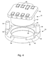
- the present invention relates in particular to the arrangement of the sensor module and its mounting mode on the bottom 11, which will now be described with reference more particularly to FIGS. 2 to 4. It will be noted that the section illustrated in FIG. in the longitudinal axis of the groove 22 of the bottom 11.
- the sensor module 30 comprises a known type of pressure sensor 31, an O-ring seal 32, an intermediate ring 33, an auxiliary printed circuit board (PCB) 34, a sensor support 35 and screws 36 passing through holes elements 34 and 35 for engaging threaded blind holes 37 with a protuberance 39 of the bottom 11 to fix the sensor module therein.
- the support 35 is traversed by other holes in which are housed helical springs 38 providing electrical connections between the auxiliary PCB 34 and the main PCB (PCB) 40 of the watch, which is placed on the upper face of the plate 4 shown in Figure 1. Note that it is possible to use, instead of the springs 58, laminated elastomeric connectors, known as zebra.
- the pressure sensor 31 comprises a rectangular insulating substrate 42, for example made of ceramic material, provided with printed circuits and on the lower face of which there is a semiconductor element 43 sensitive to the pressure and coated with a protective gel 44 which transmits the ambient pressure.
- the other face of the substrate 42 is provided with electrical terminals 46 electrically connected to the sensitive element 43 and intended to be applied against contact pads of the auxiliary PCB 34.
- the pressure sensor comprises a rigid tubular casing 47 whose rear end is sealingly attached to the substrate 42, to form a kind of pot which contains the gel 44.
- Such a type of pressure sensor is well known and supplied on the market by different manufacturers.
- the intermediate ring 33 is preferably a molded piece of synthetic material. It comprises an annular portion 50 whose outer and inner walls 51 and 51 are cylindrical, two pairs of protuberances 53 and 54 having flat inner faces which define a rectangular housing for orienting the substrate 42 of the sensor 31, and two parallel cylindrical feet 55 located outside said rectangular housing, in this case on the protuberances 53, and extending parallel to the central axis of the ring towards the inside of the watch.
- the two feet 55 are arranged to fit without play in two holes 56 of the auxiliary PCB 34 to position it accurately in its own plane, in particular with respect to the terminals 46 of the sensor 31.
- the sensor 31 is driven into the intermediate ring 33, its tubular casing 47 pressing against the inner surface 52 of the ring to ensure a perfect centering of one piece relative to the other.
- the positioning of the substrate 42 can benefit from fairly wide tolerances, since the terminals 46 do not need a very high positional accuracy with respect to the PCB 34.
- the tubular casing 47 of the sensor is protruding downwards with respect to the lower end face of the ring 33, as can be seen in particular in FIG. 2, which makes it possible to thread the O-ring 32 around the casing 47.
- the preassembled sensor module 30 can be mounted on the bottom 11 of the watch by inserting the elements 32 and 33 into the hole 12 of the bottom.
- this ring 33 may have a slight lateral play with respect to the bottom 11, the centering of the sensor module 30 in the orifice 12 being provided by the O-ring 32, but in other embodiments, it is the intermediate ring 33 which could ensure the centering in the orifice 12 by its cylindrical outer surface 51.
- the orientation of all the elements of the sensor module 30 around the central axis 60 of the orifice 12 is ensured by the engagement of the screws 36 in the threaded holes 37 and the feet 55 of the intermediate ring.
- the sensor module 30 and the protrusion 39 of the bottom 11 take place in the housing 5 shown in FIG.
- the force it exerts on the sensor 31 in the orifice 12 is transmitted through the substrate 42, the terminals 46 and the auxiliary PCB 34 to the support 35, which is rigid enough to prevent deformations of the aforementioned elements and transmit this force to the bottom 11 via screws 36.
- connection elements 38 of the sensor module will have the precise position which is suitable for being applied against the corresponding contacts of the circuits of the watch, supported by the turntable 3 of the watch.
- the invention is applicable to any watch comprising a pressure sensor, in particular a diver's watch or an altimeter watch.
Landscapes
- Physics & Mathematics (AREA)
- General Physics & Mathematics (AREA)
- Electric Clocks (AREA)
- Electromechanical Clocks (AREA)
- Measuring Fluid Pressure (AREA)
Priority Applications (9)
| Application Number | Priority Date | Filing Date | Title |
|---|---|---|---|
| DE602004028746T DE602004028746D1 (de) | 2004-12-17 | 2004-12-17 | Uhr mit einem Drucksensor |
| EP04029987A EP1672443B1 (de) | 2004-12-17 | 2004-12-17 | Uhr mit einem Drucksensor |
| TW094139286A TWI281102B (en) | 2004-12-17 | 2005-11-09 | Watch including a pressure sensor |
| CN2005101260933A CN1790196B (zh) | 2004-12-17 | 2005-11-24 | 包含压力传感器的手表 |
| SG200507867A SG123694A1 (en) | 2004-12-17 | 2005-12-02 | Watch including a pressure sensor |
| JP2005350215A JP4757004B2 (ja) | 2004-12-17 | 2005-12-05 | 圧力センサーを具備する時計 |
| KR1020050122221A KR101208876B1 (ko) | 2004-12-17 | 2005-12-13 | 압력센서를 포함한 시계 |
| US11/300,346 US7123549B2 (en) | 2004-12-17 | 2005-12-15 | Watch including a pressure sensor |
| HK06113067.5A HK1092546B (en) | 2004-12-17 | 2006-11-29 | Watch including a pressure sensor |
Applications Claiming Priority (1)
| Application Number | Priority Date | Filing Date | Title |
|---|---|---|---|
| EP04029987A EP1672443B1 (de) | 2004-12-17 | 2004-12-17 | Uhr mit einem Drucksensor |
Publications (2)
| Publication Number | Publication Date |
|---|---|
| EP1672443A1 true EP1672443A1 (de) | 2006-06-21 |
| EP1672443B1 EP1672443B1 (de) | 2010-08-18 |
Family
ID=34927832
Family Applications (1)
| Application Number | Title | Priority Date | Filing Date |
|---|---|---|---|
| EP04029987A Expired - Lifetime EP1672443B1 (de) | 2004-12-17 | 2004-12-17 | Uhr mit einem Drucksensor |
Country Status (8)
| Country | Link |
|---|---|
| US (1) | US7123549B2 (de) |
| EP (1) | EP1672443B1 (de) |
| JP (1) | JP4757004B2 (de) |
| KR (1) | KR101208876B1 (de) |
| CN (1) | CN1790196B (de) |
| DE (1) | DE602004028746D1 (de) |
| SG (1) | SG123694A1 (de) |
| TW (1) | TWI281102B (de) |
Cited By (5)
| Publication number | Priority date | Publication date | Assignee | Title |
|---|---|---|---|---|
| WO2014131562A1 (fr) * | 2013-02-27 | 2014-09-04 | Move'n See | Dispositif de mesure de pression statique, système de poursuite comprenant un tel dispositif et procédé de poursuite dudit système |
| EP3035132A1 (de) * | 2014-12-15 | 2016-06-22 | The Swatch Group Research and Development Ltd. | Ausstattungsungselement mit drucksensor |
| CN112166070A (zh) * | 2018-05-25 | 2021-01-01 | 科越思潜水股份公司 | 用于检测在潜水的呼吸装置中的压缩气瓶的压力的装置 |
| CN113515031A (zh) * | 2021-07-28 | 2021-10-19 | 歌尔科技有限公司 | 一种可切换屏幕的腕带设备 |
| CN114706287A (zh) * | 2022-04-24 | 2022-07-05 | 广东友宏医疗科技有限公司 | 一种基于红外体温检测功能的智能手表 |
Families Citing this family (32)
| Publication number | Priority date | Publication date | Assignee | Title |
|---|---|---|---|---|
| EP1806568A1 (de) * | 2004-10-28 | 2007-07-11 | Matsushita Electric Industrial Co., Ltd. | Piezoelektrisches element und verfahren zu seiner herstellung |
| FR2892225B1 (fr) * | 2005-10-14 | 2008-09-12 | Areva T & D Ag | Sectionneur de terre et procede de fabrication d'un tel sectionneur de terre |
| DE102007047133A1 (de) | 2007-10-02 | 2009-04-09 | Uemis Ag | Gehäuse für einen Tauchcomputer |
| ATE476689T1 (de) * | 2007-11-28 | 2010-08-15 | Tissot Sa | Steuervorrichtung mit druckschalter |
| EP2466394A1 (de) * | 2010-12-17 | 2012-06-20 | The Swatch Group Research and Development Ltd. | Kapsel für wissenschaftliches Instrument |
| EP2477084A1 (de) * | 2011-01-18 | 2012-07-18 | ETA SA Manufacture Horlogère Suisse | Armbanduhr mit einem elastomeren Anschluss für die elektrische Verbindung eines digitalen Anzeigegeräts mit einer Leiterplatte, und Verfahren für den Zusammenbau einer solchen Uhr |
| EP3575887A1 (de) * | 2011-10-05 | 2019-12-04 | Suunto Oy | Uhrengehäuse und armbanduhrvorrichtung |
| JP2013108942A (ja) * | 2011-11-24 | 2013-06-06 | Seiko Instruments Inc | 電子時計 |
| CN103296495A (zh) * | 2012-02-23 | 2013-09-11 | 艾默生电气公司 | 密封的电源馈通端子板组件 |
| US9864343B2 (en) * | 2013-01-18 | 2018-01-09 | Eta Sa Manufacture Horlogere Suisse | Support element for a timepiece sensor |
| US9465365B2 (en) * | 2013-10-25 | 2016-10-11 | Mark Nichol | Electronic device capable of being coupled to a wristwatch |
| KR102239316B1 (ko) * | 2014-09-02 | 2021-04-13 | 애플 인크. | 웨어러블 전자 디바이스 |
| US9575466B1 (en) | 2014-09-03 | 2017-02-21 | Fossil Group, Inc. | Sensor-enabled fashion timepiece |
| TWI588815B (zh) * | 2015-06-01 | 2017-06-21 | 仁寶電腦工業股份有限公司 | 顯示參數調整方法及使用此方法的電子裝置 |
| CN205318113U (zh) * | 2015-06-08 | 2016-06-15 | 中兴通讯股份有限公司 | 一种智能手表 |
| EP3136071B1 (de) * | 2015-08-25 | 2018-03-28 | The Swatch Group Research and Development Ltd. | Kalibriervorrichtung und -verfahren einer höhenmessvorrichtung |
| EP3168694B1 (de) * | 2015-11-11 | 2019-01-02 | Blancpain SA. | Anzeigemechanismus der aufsteigegeschwindigkeit, und mit einem solchen mechanismus ausgestattete taucheruhr |
| EP3178344A1 (de) * | 2015-12-09 | 2017-06-14 | The Swatch Group Research and Development Ltd. | Bekleidungselement in variablen farben |
| EP3182221A1 (de) * | 2015-12-15 | 2017-06-21 | Omega SA | Uhrenarmband |
| US11589758B2 (en) * | 2016-01-25 | 2023-02-28 | Fitbit, Inc. | Calibration of pulse-transit-time to blood pressure model using multiple physiological sensors and various methods for blood pressure variation |
| EP3225156B1 (de) * | 2016-03-31 | 2022-01-05 | Nokia Technologies Oy | Adaptive tragbare vorrichtung für physiologische messungen und verfahren damit |
| US20190079459A1 (en) * | 2016-04-14 | 2019-03-14 | Huawei Technologies Co., Ltd. | Smartwatch with pressure sensing function |
| US10409226B2 (en) * | 2016-06-01 | 2019-09-10 | Withings | Wearable device with air quality sensor |
| KR102558476B1 (ko) | 2016-07-21 | 2023-07-25 | 삼성전자 주식회사 | 압력 센서를 구비한 전자 장치 |
| KR20180051227A (ko) * | 2016-11-08 | 2018-05-16 | 엘지전자 주식회사 | 와치타입 단말기 |
| CN106444353A (zh) * | 2016-12-13 | 2017-02-22 | 东莞市准点塑胶电子有限公司 | 一种指针式蓝牙智能校时时钟机心 |
| US10684656B2 (en) * | 2017-09-18 | 2020-06-16 | Apple Inc. | Intelligent vents for electronic devices |
| CN107976897B (zh) * | 2017-11-20 | 2020-06-19 | 深圳市沃特沃德股份有限公司 | 传感器连接组件及穿戴设备 |
| CN112806678B (zh) * | 2021-01-20 | 2023-04-07 | 维沃移动通信有限公司 | 一种手表 |
| JP7428193B2 (ja) * | 2021-06-24 | 2024-02-06 | カシオ計算機株式会社 | 滑り押え部材、その製造方法、および時計 |
| US12396686B2 (en) | 2021-08-31 | 2025-08-26 | Apple Inc. | Sensing health parameters in wearable devices |
| DE102022204785A1 (de) | 2022-05-16 | 2023-11-16 | Robert Bosch Gesellschaft mit beschränkter Haftung | Tragbares elektronisches Gerät, sowie System und Verfahren zur Ermittlung einer vertikalen Position |
Citations (7)
| Publication number | Priority date | Publication date | Assignee | Title |
|---|---|---|---|---|
| US4783772A (en) * | 1985-03-19 | 1988-11-08 | Citizen Watch Co., Ltd. | Wristwatch with pressure sensor |
| JPH05288626A (ja) * | 1992-04-07 | 1993-11-02 | Casio Comput Co Ltd | 圧力センサ |
| EP0677798A2 (de) * | 1994-04-14 | 1995-10-18 | Citizen Watch Co., Ltd. | Uhr mit Detektor |
| US5500835A (en) * | 1994-03-04 | 1996-03-19 | Asulab S.A. | Weather forecasting watch |
| EP1006418A1 (de) * | 1998-06-22 | 2000-06-07 | Seiko Epson Corporation | Stuktur zur montage eines fühlers, elektronische vorrichtung sowie uhr mit einersolchen struktur |
| JP2000292559A (ja) * | 1999-04-06 | 2000-10-20 | Seiko Instruments Inc | センサ付き電子機器 |
| EP1544696A2 (de) * | 2003-12-17 | 2005-06-22 | ETA SA Manufacture Horlogère Suisse | Tragbares elektronisches Gerät, das mit einem Drucksensor ausgerüstet ist |
Family Cites Families (4)
| Publication number | Priority date | Publication date | Assignee | Title |
|---|---|---|---|---|
| JPH08285963A (ja) * | 1995-04-11 | 1996-11-01 | Citizen Watch Co Ltd | センサ付き時計 |
| JP3397888B2 (ja) * | 1994-05-31 | 2003-04-21 | シチズン時計株式会社 | センサ付き時計 |
| CH691334A5 (fr) * | 1997-08-28 | 2001-06-29 | Asulab Sa | Appareillage susceptible d'être immergé et comprenant un transducteur sonore. |
| CN1145861C (zh) * | 1998-12-23 | 2004-04-14 | 阿苏拉布股份有限公司 | 提供气压计或高度计读数的手表及其制造方法 |
-
2004
- 2004-12-17 EP EP04029987A patent/EP1672443B1/de not_active Expired - Lifetime
- 2004-12-17 DE DE602004028746T patent/DE602004028746D1/de not_active Expired - Lifetime
-
2005
- 2005-11-09 TW TW094139286A patent/TWI281102B/zh not_active IP Right Cessation
- 2005-11-24 CN CN2005101260933A patent/CN1790196B/zh not_active Expired - Lifetime
- 2005-12-02 SG SG200507867A patent/SG123694A1/en unknown
- 2005-12-05 JP JP2005350215A patent/JP4757004B2/ja not_active Expired - Lifetime
- 2005-12-13 KR KR1020050122221A patent/KR101208876B1/ko not_active Expired - Lifetime
- 2005-12-15 US US11/300,346 patent/US7123549B2/en not_active Expired - Lifetime
Patent Citations (7)
| Publication number | Priority date | Publication date | Assignee | Title |
|---|---|---|---|---|
| US4783772A (en) * | 1985-03-19 | 1988-11-08 | Citizen Watch Co., Ltd. | Wristwatch with pressure sensor |
| JPH05288626A (ja) * | 1992-04-07 | 1993-11-02 | Casio Comput Co Ltd | 圧力センサ |
| US5500835A (en) * | 1994-03-04 | 1996-03-19 | Asulab S.A. | Weather forecasting watch |
| EP0677798A2 (de) * | 1994-04-14 | 1995-10-18 | Citizen Watch Co., Ltd. | Uhr mit Detektor |
| EP1006418A1 (de) * | 1998-06-22 | 2000-06-07 | Seiko Epson Corporation | Stuktur zur montage eines fühlers, elektronische vorrichtung sowie uhr mit einersolchen struktur |
| JP2000292559A (ja) * | 1999-04-06 | 2000-10-20 | Seiko Instruments Inc | センサ付き電子機器 |
| EP1544696A2 (de) * | 2003-12-17 | 2005-06-22 | ETA SA Manufacture Horlogère Suisse | Tragbares elektronisches Gerät, das mit einem Drucksensor ausgerüstet ist |
Non-Patent Citations (2)
| Title |
|---|
| PATENT ABSTRACTS OF JAPAN vol. 018, no. 078 (P - 1689) 8 February 1994 (1994-02-08) * |
| PATENT ABSTRACTS OF JAPAN vol. 2000, no. 13 5 February 2001 (2001-02-05) * |
Cited By (5)
| Publication number | Priority date | Publication date | Assignee | Title |
|---|---|---|---|---|
| WO2014131562A1 (fr) * | 2013-02-27 | 2014-09-04 | Move'n See | Dispositif de mesure de pression statique, système de poursuite comprenant un tel dispositif et procédé de poursuite dudit système |
| EP3035132A1 (de) * | 2014-12-15 | 2016-06-22 | The Swatch Group Research and Development Ltd. | Ausstattungsungselement mit drucksensor |
| CN112166070A (zh) * | 2018-05-25 | 2021-01-01 | 科越思潜水股份公司 | 用于检测在潜水的呼吸装置中的压缩气瓶的压力的装置 |
| CN113515031A (zh) * | 2021-07-28 | 2021-10-19 | 歌尔科技有限公司 | 一种可切换屏幕的腕带设备 |
| CN114706287A (zh) * | 2022-04-24 | 2022-07-05 | 广东友宏医疗科技有限公司 | 一种基于红外体温检测功能的智能手表 |
Also Published As
| Publication number | Publication date |
|---|---|
| US7123549B2 (en) | 2006-10-17 |
| JP2006170985A (ja) | 2006-06-29 |
| TW200632604A (en) | 2006-09-16 |
| SG123694A1 (en) | 2006-07-26 |
| CN1790196A (zh) | 2006-06-21 |
| DE602004028746D1 (de) | 2010-09-30 |
| EP1672443B1 (de) | 2010-08-18 |
| KR101208876B1 (ko) | 2012-12-10 |
| JP4757004B2 (ja) | 2011-08-24 |
| TWI281102B (en) | 2007-05-11 |
| US20060133213A1 (en) | 2006-06-22 |
| KR20060069269A (ko) | 2006-06-21 |
| HK1092546A1 (en) | 2007-02-09 |
| CN1790196B (zh) | 2010-06-16 |
Similar Documents
| Publication | Publication Date | Title |
|---|---|---|
| EP1672443B1 (de) | Uhr mit einem Drucksensor | |
| EP1407513B1 (de) | Antenne für armbanduhr | |
| EP1513221A1 (de) | Tragbares Armbandgerät mit elektrischem Verbindungselement durchs Gehäuse und Verfahren zur Montage des Verbindungselements | |
| EP1584001B1 (de) | Tragbare straffe einrichtung mit elektroakustischem wandler | |
| JP4052263B2 (ja) | 圧力センサ | |
| EP2607972A1 (de) | Dichter Druckknopf für Armbanduhr | |
| WO2000039644A1 (fr) | Montre fournissant une indication barometrique ou altimetrique, et son procede de fabrication | |
| EP1434114B1 (de) | Uhrengehäuse mit Boden oder Deckel mit Bajonettverschluss der manuell geöffnet werden kann | |
| EP0710900A1 (de) | Uhr mit einer in einem metallischen Gehäuse montierten wasserdichten Schale | |
| EP3798745A1 (de) | Unterteil eines armbanduhrengehäuses mit drahtloser elektronischer aufladevorrichtung von einer energiequelle | |
| EP1431847B1 (de) | Tragbares elektronisches Gerät, insbesondere Uhr, mit einer Antenne, die aus einer Spule mit grossem Diameter gebildet ist | |
| FR2485220A1 (fr) | Bati et bloc modulaires pour instruments horaires | |
| FR2629662A1 (fr) | Capsule electroacoustique a bobine rapportee | |
| JP3684724B2 (ja) | 圧力検出器 | |
| EP0844685A1 (de) | Uhr mit Antenne zum Empfangen und/oder Aussenden von Funksignalen | |
| EP2946251A1 (de) | Träger für einen uhrsensor | |
| EP1544696B1 (de) | Tragbares elektronisches Gerät, das mit einem Drucksensor ausgerüstet ist | |
| FR2867854A1 (fr) | Detecteur de pression compact, tres precis et resistant fortement a la corrosion | |
| EP1939017A1 (de) | Elektronische Einheit zur Funktionsparametermessung eines auf ein Fahrzeugrad montierten Reifens | |
| EP0899635B1 (de) | Vorrichtung zur Verwendung unter Wasser und mit einem Schallwandler | |
| EP1063632A1 (de) | Wasserdichte Vorrichtung zur Verwendung unter Wasser und mit einem Schallwandler | |
| EP1455165A1 (de) | Miniaturisierter Sensor | |
| EP1513222B1 (de) | Tragbares Armbandgerät mit elektrischem Verbindungselement durchs Gehäuse und Verfahren zur Montage des Verbindungselements | |
| JP2004045076A (ja) | 圧力センサ | |
| EP0398212B1 (de) | Telefon-Handapparat |
Legal Events
| Date | Code | Title | Description |
|---|---|---|---|
| PUAI | Public reference made under article 153(3) epc to a published international application that has entered the european phase |
Free format text: ORIGINAL CODE: 0009012 |
|
| AK | Designated contracting states |
Kind code of ref document: A1 Designated state(s): AT BE BG CH CY CZ DE DK EE ES FI FR GB GR HU IE IS IT LI LT LU MC NL PL PT RO SE SI SK TR |
|
| AX | Request for extension of the european patent |
Extension state: AL BA HR LV MK YU |
|
| 17P | Request for examination filed |
Effective date: 20061221 |
|
| AKX | Designation fees paid |
Designated state(s): CH DE FI FR GB LI |
|
| GRAP | Despatch of communication of intention to grant a patent |
Free format text: ORIGINAL CODE: EPIDOSNIGR1 |
|
| RIC1 | Information provided on ipc code assigned before grant |
Ipc: G04G 21/02 20100101AFI20100222BHEP |
|
| GRAS | Grant fee paid |
Free format text: ORIGINAL CODE: EPIDOSNIGR3 |
|
| GRAA | (expected) grant |
Free format text: ORIGINAL CODE: 0009210 |
|
| AK | Designated contracting states |
Kind code of ref document: B1 Designated state(s): CH DE FI FR GB LI |
|
| REG | Reference to a national code |
Ref country code: GB Ref legal event code: FG4D Free format text: NOT ENGLISH |
|
| REG | Reference to a national code |
Ref country code: CH Ref legal event code: EP |
|
| REF | Corresponds to: |
Ref document number: 602004028746 Country of ref document: DE Date of ref document: 20100930 Kind code of ref document: P |
|
| REG | Reference to a national code |
Ref country code: CH Ref legal event code: NV Representative=s name: ICB INGENIEURS CONSEILS EN BREVETS SA |
|
| PLBE | No opposition filed within time limit |
Free format text: ORIGINAL CODE: 0009261 |
|
| STAA | Information on the status of an ep patent application or granted ep patent |
Free format text: STATUS: NO OPPOSITION FILED WITHIN TIME LIMIT |
|
| 26N | No opposition filed |
Effective date: 20110519 |
|
| REG | Reference to a national code |
Ref country code: DE Ref legal event code: R097 Ref document number: 602004028746 Country of ref document: DE Effective date: 20110519 |
|
| REG | Reference to a national code |
Ref country code: FR Ref legal event code: PLFP Year of fee payment: 12 |
|
| REG | Reference to a national code |
Ref country code: FR Ref legal event code: PLFP Year of fee payment: 13 |
|
| REG | Reference to a national code |
Ref country code: FR Ref legal event code: PLFP Year of fee payment: 14 |
|
| P01 | Opt-out of the competence of the unified patent court (upc) registered |
Effective date: 20230611 |
|
| PGFP | Annual fee paid to national office [announced via postgrant information from national office to epo] |
Ref country code: GB Payment date: 20231121 Year of fee payment: 20 |
|
| PGFP | Annual fee paid to national office [announced via postgrant information from national office to epo] |
Ref country code: FR Payment date: 20231122 Year of fee payment: 20 Ref country code: FI Payment date: 20231121 Year of fee payment: 20 Ref country code: DE Payment date: 20231121 Year of fee payment: 20 |
|
| PGFP | Annual fee paid to national office [announced via postgrant information from national office to epo] |
Ref country code: CH Payment date: 20240101 Year of fee payment: 20 |
|
| REG | Reference to a national code |
Ref country code: DE Ref legal event code: R071 Ref document number: 602004028746 Country of ref document: DE |
|
| REG | Reference to a national code |
Ref country code: CH Ref legal event code: PL |
|
| REG | Reference to a national code |
Ref country code: GB Ref legal event code: PE20 Expiry date: 20241216 |
|
| PG25 | Lapsed in a contracting state [announced via postgrant information from national office to epo] |
Ref country code: GB Free format text: LAPSE BECAUSE OF EXPIRATION OF PROTECTION Effective date: 20241216 |
|
| PG25 | Lapsed in a contracting state [announced via postgrant information from national office to epo] |
Ref country code: GB Free format text: LAPSE BECAUSE OF EXPIRATION OF PROTECTION Effective date: 20241216 |