EP1672459A2 - Procédé de commande du PH d'une solution électrolysée utilisant un dispositif microfluidique comprenant un électrolyseur - Google Patents
Procédé de commande du PH d'une solution électrolysée utilisant un dispositif microfluidique comprenant un électrolyseur Download PDFInfo
- Publication number
- EP1672459A2 EP1672459A2 EP05025575A EP05025575A EP1672459A2 EP 1672459 A2 EP1672459 A2 EP 1672459A2 EP 05025575 A EP05025575 A EP 05025575A EP 05025575 A EP05025575 A EP 05025575A EP 1672459 A2 EP1672459 A2 EP 1672459A2
- Authority
- EP
- European Patent Office
- Prior art keywords
- chamber
- anode
- cathode
- solution
- anode chamber
- Prior art date
- Legal status (The legal status is an assumption and is not a legal conclusion. Google has not performed a legal analysis and makes no representation as to the accuracy of the status listed.)
- Granted
Links
Images

Classifications
-
- B—PERFORMING OPERATIONS; TRANSPORTING
- B01—PHYSICAL OR CHEMICAL PROCESSES OR APPARATUS IN GENERAL
- B01L—CHEMICAL OR PHYSICAL LABORATORY APPARATUS FOR GENERAL USE
- B01L3/00—Containers or dishes for laboratory use, e.g. laboratory glassware; Droppers
- B01L3/50—Containers for the purpose of retaining a material to be analysed, e.g. test tubes
- B01L3/502—Containers for the purpose of retaining a material to be analysed, e.g. test tubes with fluid transport, e.g. in multi-compartment structures
- B01L3/5027—Containers for the purpose of retaining a material to be analysed, e.g. test tubes with fluid transport, e.g. in multi-compartment structures by integrated microfluidic structures, i.e. dimensions of channels and chambers are such that surface tension forces are important, e.g. lab-on-a-chip
- B01L3/502715—Containers for the purpose of retaining a material to be analysed, e.g. test tubes with fluid transport, e.g. in multi-compartment structures by integrated microfluidic structures, i.e. dimensions of channels and chambers are such that surface tension forces are important, e.g. lab-on-a-chip characterised by interfacing components, e.g. fluidic, electrical, optical or mechanical interfaces
-
- G—PHYSICS
- G05—CONTROLLING; REGULATING
- G05D—SYSTEMS FOR CONTROLLING OR REGULATING NON-ELECTRIC VARIABLES
- G05D21/00—Control of chemical or physico-chemical variables, e.g. pH value
- G05D21/02—Control of chemical or physico-chemical variables, e.g. pH value characterised by the use of electric means
-
- B—PERFORMING OPERATIONS; TRANSPORTING
- B01—PHYSICAL OR CHEMICAL PROCESSES OR APPARATUS IN GENERAL
- B01D—SEPARATION
- B01D61/00—Processes of separation using semi-permeable membranes, e.g. dialysis, osmosis or ultrafiltration; Apparatus, accessories or auxiliary operations specially adapted therefor
- B01D61/42—Electrodialysis; Electro-osmosis ; Electro-ultrafiltration; Membrane capacitive deionization
- B01D61/422—Electrodialysis
-
- C—CHEMISTRY; METALLURGY
- C02—TREATMENT OF WATER, WASTE WATER, SEWAGE, OR SLUDGE
- C02F—TREATMENT OF WATER, WASTE WATER, SEWAGE, OR SLUDGE
- C02F1/00—Treatment of water, waste water, or sewage
- C02F1/46—Treatment of water, waste water, or sewage by electrochemical methods
- C02F1/461—Treatment of water, waste water, or sewage by electrochemical methods by electrolysis
- C02F1/46104—Devices therefor; Their operating or servicing
- C02F1/4618—Devices therefor; Their operating or servicing for producing "ionised" acidic or basic water
-
- B—PERFORMING OPERATIONS; TRANSPORTING
- B01—PHYSICAL OR CHEMICAL PROCESSES OR APPARATUS IN GENERAL
- B01L—CHEMICAL OR PHYSICAL LABORATORY APPARATUS FOR GENERAL USE
- B01L2200/00—Solutions for specific problems relating to chemical or physical laboratory apparatus
- B01L2200/14—Process control and prevention of errors
-
- B—PERFORMING OPERATIONS; TRANSPORTING
- B01—PHYSICAL OR CHEMICAL PROCESSES OR APPARATUS IN GENERAL
- B01L—CHEMICAL OR PHYSICAL LABORATORY APPARATUS FOR GENERAL USE
- B01L2300/00—Additional constructional details
- B01L2300/06—Auxiliary integrated devices, integrated components
- B01L2300/0627—Sensor or part of a sensor is integrated
- B01L2300/0645—Electrodes
-
- B—PERFORMING OPERATIONS; TRANSPORTING
- B01—PHYSICAL OR CHEMICAL PROCESSES OR APPARATUS IN GENERAL
- B01L—CHEMICAL OR PHYSICAL LABORATORY APPARATUS FOR GENERAL USE
- B01L2300/00—Additional constructional details
- B01L2300/06—Auxiliary integrated devices, integrated components
- B01L2300/0681—Filter
-
- B—PERFORMING OPERATIONS; TRANSPORTING
- B01—PHYSICAL OR CHEMICAL PROCESSES OR APPARATUS IN GENERAL
- B01L—CHEMICAL OR PHYSICAL LABORATORY APPARATUS FOR GENERAL USE
- B01L2300/00—Additional constructional details
- B01L2300/08—Geometry, shape and general structure
- B01L2300/0861—Configuration of multiple channels and/or chambers in a single devices
- B01L2300/0867—Multiple inlets and one sample wells, e.g. mixing, dilution
-
- B—PERFORMING OPERATIONS; TRANSPORTING
- B01—PHYSICAL OR CHEMICAL PROCESSES OR APPARATUS IN GENERAL
- B01L—CHEMICAL OR PHYSICAL LABORATORY APPARATUS FOR GENERAL USE
- B01L2400/00—Moving or stopping fluids
- B01L2400/04—Moving fluids with specific forces or mechanical means
- B01L2400/0403—Moving fluids with specific forces or mechanical means specific forces
- B01L2400/0415—Moving fluids with specific forces or mechanical means specific forces electrical forces, e.g. electrokinetic
-
- B—PERFORMING OPERATIONS; TRANSPORTING
- B01—PHYSICAL OR CHEMICAL PROCESSES OR APPARATUS IN GENERAL
- B01L—CHEMICAL OR PHYSICAL LABORATORY APPARATUS FOR GENERAL USE
- B01L3/00—Containers or dishes for laboratory use, e.g. laboratory glassware; Droppers
- B01L3/50—Containers for the purpose of retaining a material to be analysed, e.g. test tubes
- B01L3/502—Containers for the purpose of retaining a material to be analysed, e.g. test tubes with fluid transport, e.g. in multi-compartment structures
- B01L3/5027—Containers for the purpose of retaining a material to be analysed, e.g. test tubes with fluid transport, e.g. in multi-compartment structures by integrated microfluidic structures, i.e. dimensions of channels and chambers are such that surface tension forces are important, e.g. lab-on-a-chip
- B01L3/50273—Containers for the purpose of retaining a material to be analysed, e.g. test tubes with fluid transport, e.g. in multi-compartment structures by integrated microfluidic structures, i.e. dimensions of channels and chambers are such that surface tension forces are important, e.g. lab-on-a-chip characterised by the means or forces applied to move the fluids
-
- C—CHEMISTRY; METALLURGY
- C02—TREATMENT OF WATER, WASTE WATER, SEWAGE, OR SLUDGE
- C02F—TREATMENT OF WATER, WASTE WATER, SEWAGE, OR SLUDGE
- C02F2103/00—Nature of the water, waste water, sewage or sludge to be treated
- C02F2103/02—Non-contaminated water, e.g. for industrial water supply
-
- C—CHEMISTRY; METALLURGY
- C02—TREATMENT OF WATER, WASTE WATER, SEWAGE, OR SLUDGE
- C02F—TREATMENT OF WATER, WASTE WATER, SEWAGE, OR SLUDGE
- C02F2201/00—Apparatus for treatment of water, waste water or sewage
- C02F2201/46—Apparatus for electrochemical processes
- C02F2201/461—Electrolysis apparatus
- C02F2201/46105—Details relating to the electrolytic devices
- C02F2201/4611—Fluid flow
-
- C—CHEMISTRY; METALLURGY
- C02—TREATMENT OF WATER, WASTE WATER, SEWAGE, OR SLUDGE
- C02F—TREATMENT OF WATER, WASTE WATER, SEWAGE, OR SLUDGE
- C02F2201/00—Apparatus for treatment of water, waste water or sewage
- C02F2201/46—Apparatus for electrochemical processes
- C02F2201/461—Electrolysis apparatus
- C02F2201/46105—Details relating to the electrolytic devices
- C02F2201/46115—Electrolytic cell with membranes or diaphragms
-
- C—CHEMISTRY; METALLURGY
- C02—TREATMENT OF WATER, WASTE WATER, SEWAGE, OR SLUDGE
- C02F—TREATMENT OF WATER, WASTE WATER, SEWAGE, OR SLUDGE
- C02F2201/00—Apparatus for treatment of water, waste water or sewage
- C02F2201/46—Apparatus for electrochemical processes
- C02F2201/461—Electrolysis apparatus
- C02F2201/46105—Details relating to the electrolytic devices
- C02F2201/4618—Supplying or removing reactants or electrolyte
-
- C—CHEMISTRY; METALLURGY
- C02—TREATMENT OF WATER, WASTE WATER, SEWAGE, OR SLUDGE
- C02F—TREATMENT OF WATER, WASTE WATER, SEWAGE, OR SLUDGE
- C02F2209/00—Controlling or monitoring parameters in water treatment
- C02F2209/06—Controlling or monitoring parameters in water treatment pH
-
- Y—GENERAL TAGGING OF NEW TECHNOLOGICAL DEVELOPMENTS; GENERAL TAGGING OF CROSS-SECTIONAL TECHNOLOGIES SPANNING OVER SEVERAL SECTIONS OF THE IPC; TECHNICAL SUBJECTS COVERED BY FORMER USPC CROSS-REFERENCE ART COLLECTIONS [XRACs] AND DIGESTS
- Y02—TECHNOLOGIES OR APPLICATIONS FOR MITIGATION OR ADAPTATION AGAINST CLIMATE CHANGE
- Y02E—REDUCTION OF GREENHOUSE GAS [GHG] EMISSIONS, RELATED TO ENERGY GENERATION, TRANSMISSION OR DISTRIBUTION
- Y02E60/00—Enabling technologies; Technologies with a potential or indirect contribution to GHG emissions mitigation
- Y02E60/30—Hydrogen technology
- Y02E60/36—Hydrogen production from non-carbon containing sources, e.g. by water electrolysis
Definitions
- the present invention relates to a method of controlling the pH of a solution using a microfluidic device including an electrolysis device.
- Microfluidic devices refer to devices in which an inlet, an outlet, a reaction chamber, etc., are interconnected through microchannels. Such devices are widely known in the field and are used in micro-analytic devices, such as a lab-on-a-chip (LOC). In addition to microchannels, a micropump for inducing the flow of fluid, a micromixer for mixing fluids, a microfilter for filtering a fluid, etc., are included in microfluidic devices.
- LOC lab-on-a-chip
- a microfluidic device used as a biological analytic device performs a series of biological analytic processes, such as cytolysis, nucleic acid amplification and separation, such as polymerase chain reaction (PCR), and protein separation and detection.
- a conventional pH control process involved in such biological analysis processes is achieved by adding or removing an acidic solution, a neutral solution, or a buffer solution.
- problems associated with dilution, mixing and the flow of a substance in a microchannel may arise because a small amount of sample is used.
- the added pH-adjusting material may inhibit subsequent biological analysis processes. In this case, the pH-adjusting material has to be removed.
- the inventors of the present invention found a method of controlling pH using electrolysis in a microfluidic device, in which the volume ratio of anode and cathode chambers is controlled, and solutions generated in the anode and cathode chambers through electrolysis are mixed in the equal volumes, and completed the prevent invention.
- the present invention provides a method of controlling pH using a microfluidic device including an electrolyzing device.
- a method of controlling the pH of a solution using electrolysis in a microfluidic device comprising an electrolysis device including an anode chamber, a cathode chamber, and a partition membrane between the anode chamber and the cathode chamber, wherein the anode chamber includes an inlet and an outlet through which an anode chamber solution enters and is discharged from the anode chamber, respectively, and an electrode, and the cathode chamber includes an inlet and an outlet through which a cathode chamber solution enters and is discharged from the cathode chamber, respectively, and an electrode, the method comprising: flowing the anode chamber solution containing a compound having a lower standard oxidation potential than water into the anode chamber through the inlet of the anode chamber; flowing the cathode chamber solution containing a compound having a lower standard reduction potential than water into the cathode chamber through the inlet of the cathode chamber; applying a voltage between the electrode in the an electrolysis device including an anode chamber,
- a method of controlling pH uses electrolysis in a microfluidic device comprising an electrolysis device including an anode chamber, a cathode chamber, and a partition membrane between the anode chamber and the cathode chamber, wherein the anode chamber includes an inlet and an outlet through which an anode chamber solution enters and is discharged from the anode chamber, respectively, and an electrode, and the cathode chamber includes an inlet and an outlet through which a cathode chamber solution enters and is discharged from the cathode chamber, respectively, and an electrode.
- the method according to the present invention includes: flowing the anode chamber solution containing a compound having a lower standard oxidation potential than water into the anode chamber through the inlet of the anode chamber; flowing the cathode chamber solution containing a compound having a lower standard reduction potential than water into the cathode chamber through the inlet of the cathode chamber; applying a voltage between the electrode in the anode chamber and the electrode in the cathode chamber to induce electrolysis in the anode chamber and the cathode chamber thereby producing an acidic anode-electrolyzed solution and a basic cathode-electrolyzed solution; and mixing equal volumes of the acidic anode-electrolyzed solution and the basic cathode-electrolyzed solution, wherein the volumes of the cathode chamber and the anode chamber are controlled in a predetermined ratio according to a target pH of a solution obtained by mixing the acidic anode-electrolyzed solution and the basic
- the method according to the present invention includes (a) flowing an anode chamber solution containing a compound having a lower standard oxidation potential than water into the anode chamber through the inlet of the anode chamber and (b) flowing a cathode chamber solution containing a compound containing a cell or a virus and having a lower standard reduction potential than water into the cathode chamber through the inlet of the cathode chamber.
- the compound having a lower standard oxidation potential than water may be, but is not limited to, a compound containing at least one kind of anions selected from the group consisting of NO 3 - , F-, SO 4 2- , PO 4 3 -, and CO 3 2- .
- the compound having a lower standard reduction potential than water may be, but is not limited to, a compound containing at least one kind of cations selected from the group consisting of Na + , K + , Ca 2+ , Mg 2+ , and Al 3+ .
- (a) and (b) may be simultaneously or sequentially performed.
- the partition membrane may pass current and block ions and gas generated as a result of the electrolysis of the electrolyzed solutions in the anode and cathode chambers.
- the partition membrane may pass current, but do not pass hydrogen ions and hydroxide ions and/or gas.
- the partition membrane include, but are not limited to, NafionTM(Dupont), DowexTM (Aldrich), DiaionTM (Aldrich), etc.
- the electrodes in the anode and cathode chambers of the electrolysis device used in the method according to the present invention may be formed of one of platinum, gold, copper, palladium, etc.
- a platinum electrode is used in the anode chamber, the adsorption of protein and DNA can be prevented.
- a copper electrode is used in the anode chamber, the copper electrode can form CuCl 2 through the reaction with chlorine ions included in, for example, NaCl, contained in the anode chamber, thereby suppressing the generation of toxic chlorine gas.
- the palladium electrode absorbs hydrogen gas generated in the cathode chamber, and thus an additional degassing process is unnecessary.
- the method according to the present invention may further include (c) applying a voltage across the electrodes in the anode chamber and the cathode chamber to induce electrolysis in the anode chamber and the cathode chamber.
- a cathode chamber solution including the compound having a lower standard reduction potential than water is contained in the cathode chamber, hydrogen gas and hydroxide ions (OH - ) are generated in the cathode chamber as a result of the electrolysis of water.
- an anode chamber solution including the compound having a lower standard reduction potential than water is contained in the anode chamber, oxygen gas and hydrogen ions (H + ) are generated in the anode chamber as a result of the electrolysis of water.
- the cathode chamber solution has an alkaline pH
- the anode chamber solution has an acidic pH.
- a biological analytic microfluidic device such as a lab-on-a-chip, perform various biological analysis processes, such as cell lysis, PCR, nucleic acid separation, protein separation, etc. Most of such biological analysis processes are performed at a neutral pH because biological molecules, such as nucleic acids or proteins are stable in a neutral condition.
- a series of processes involving cell lysis, nucleic acid separation and amplification, protein separation and detection, etc. may be performed in a microfluidic device.
- a solution obtained as a result of the reaction in each of the processes must not include any substance affecting reaction in a subsequent process. This solution may have a neutral pH or a pH not affecting a subsequent reaction.
- the method according to the present invention may include (d) mixing equal volumes of an acidic anode-electrolyzed solution (anode chamber solution) and a basic cathode-electrolyzed solution (cathode chamber solution), which are obtained as a result of the electrolysis in the anode and cathode chambers.
- the mixing the equal volumes of the electrolyzed solutions can be achieved, for example, using one pump, which is installed in a microchannel formed by merging an outlet microchannel of the anode chamber and an outlet microchannel of the cathode chamber.
- the equal volumes of the electrolyzed solutions can be mixed without measuring the volumes of the electrolyzed solutions flowing out through the outlet microchannels of the anode and cathode chambers.
- a flowmeter is not required.
- equal volumes of the electrolyzed solution flowing out through the outlet microchannel of the anode chamber and the electrolyzed solution flowing out through the outlet microchannel of the cathode chamber may be measured and then mixed.
- methods of mixing equal volumes of the electrolyzed solutions that can be used in the present invention are not limited to the methods described above.
- the electrolysis device further comprises a pump which is disposed in a microchannel formed by merging the outlet microchannel of the anode chamber and the outlet microchannel of the cathode chamber.
- the volumes of the cathode chamber and the anode chamber are determined in a predetermined ratio according to a target pH of a mixed solution of the anode-electrolyzed solution and the cathode-electrolyzed solution.
- a total equivalent of hydrogen ions generated in the anode chamber and a total equivalent of hydroxide ions generated in the cathode chamber are the same. Therefore, when a total amount of the anode chamber solution and a total amount of the cathode chamber solution are mixed together, an initial pH of a sample is obtained. In other words, there is no need to additionally adjust the pH of the sample for various processes.
- the volumes of the anode chamber and the cathode chamber are varied in a predetermined ratio to produce electrolyzed solutions having different ionic concentrations in the anode and cathode chambers so that the electrolyzed solutions in the anode and cathode chambers are mixed in the same volume to obtain a solution having a target pH.
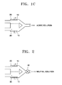
- FIGS. 1A through 1 C illustrate the principle of a method of controlling pH according to an embodiment of the present invention.
- FIG. 1A when the volumes of an anode chamber 20 and a cathode chamber 30 are the same, after electrolysis is induced by supplying a voltage to electrodes 10 in the anode chamber 20 and the cathode chamber 30, a total equivalent of hydrogen ions generated in the anode chamber 20 is equal to a total equivalent of hydroxide ions generated in the cathode chamber 30. Therefore, when equal volumes of an anode chamber solution and a cathode chamber solution are mixed, the mixed solution has a neutral pH.
- the concentration of hydrogen ions generated in the anode chamber 20 is lower than the concentration of hydroxide ions generated in the cathode chamber 30. Therefore, when equal volumes of the anode chamber solution and the cathode chamber solution are mixed , the mixed solution has an alkaline pH.
- the concentration of hydroxide ions generated in the cathode chamber 30 is lower than the concentration of hydrogen ions generated in the anode chamber 20. Therefore, when equal volumes of the anode chamber solution and the cathode chamber solution are mixed, the mixed solution has an acidic pH.
- a target pH of the final mixed solution can be determined according to the concentrations of hydrogen ions and hydroxide ions generated in the anode and cathode chambers that are calculated with reference to the standard reduction potentials of electrolytic solutions in the anode and cathode chambers and the volumes of the anode and cathode chambers in a microfluidic device used in the method of the present invention.
- a target pH of the final mixed solution can be experimentally determined according to the method comprising; making a microfluidic device used in the method of the present invention including an electrolysis device having an anode chamber and a cathode chamber in a varying volume ratio between the anode chamber and the cathode chamber; flowing the anode chamber solution containing a compound having a lower standard oxidation potential than water into the anode chamber through the inlet of the anode chamber; flowing the cathode chamber solution containing a compound having a lower standard reduction potential than water into the cathode chamber through the inlet of the cathode chamber; applying a voltage between the electrode in the anode chamber and the electrode in the cathode chamber to induce electrolysis in the anode chamber and the cathode chamber; mixing equal volumes of the acidic anode-electrolyzed solution and the basic cathode-electrolyzed solution, and measuring the target pH of the final mixed solution.
- the target pH of the final mixed solution can be easily determined by one of ordinary skill in the art according to a selected electrolytic solution.
- the volume ratio between the anode chamber and the cathode chamber can be determined according to a target pH and a sample solution.
- the volume ratio of the anode chamber and the cathode chamber determined as described above can be used when manufacturing an electrolysis device to be used in the method according to the present invention in which a target pH can be achieved by just mixing equal volumes of the electrolyzed solution in the anode chamber and the electrolyzed solution in the cathode chamber.
- Example 1 pH control based on the volume ratio of anode chamber to cathode chamber
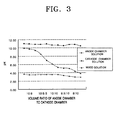
- FIG. 2 illustrates a structure of the electrolysis device used in Example 1 according to the present invention.
- a gold electrode and a platinum electrode are respectively installed in a cathode chamber and an anode chamber.
- the cathode chamber and the anode chamber are divided by a partition membrane NafionTM (Dupont, U.S.A).
- Example 1 electrolysis devices with the anode chamber 20 and the cathode chamber 30 in different volume ratios were manufactured, wherein the total volume of the anode chamber 20 and the cathode chamber 30 in each of the electrolysis devices was 10 mL.
- the anode chamber 20 was filled with 100 mM Na 2 SO 4
- the cathode chamber 30 was filled with 100 mM NaCl.
- a 5V-DC voltage was supplied across the electrodes 10 for 1 minute to induce electrolysis.
- Electrolyzed solutions in the anode chamber 20 and the cathode chamber 30 were mixed using a pump 40 to obtain a mixed solution.
- the pump 40 is disposed in a microchannel formed by merging the outlet microchannel of the anode chamber and the outlet microchannel of the cathode chamber.
- the pH of the mixed solution was measured.
- the volume ratio of the anode chamber and the cathode chamber in each of the electrolysis devices used in Example 1, pH of each of anode and cathode chamber solutions, and pH of each of the mixed solutions are shown in Table 1.
- FIG. 3 is a graph obtained from the data of Table 1.
- the resistance during electrolysis varies according to the concentration and the kind of a salt in a sample solution, and the concentration of ions generated as a result of the electrolysis varies. Therefore, in general, a process of adjusting the volume ratio of electrolyzed solutions while measuring the pH of a mixed solution to obtain a target pH and a device for adjusting the volume ratio of the electrolyzed solutions are required.
- a biological sample solution containing NaCl which is the highest concentration among components, is flowed into the anode and cathode chambers and electrolyzed therein, a chlorine gas is generated in the anode chamber as a result of the electrolysis of chlorine ions, not water.
- the concentration of hydrogen ions generated in the anode chamber is lower than the concentration of hydroxide ions generated in the cathode chamber. Furthermore, the hydrogen ions generated in the anode chamber are the product of a reaction between the chlorine gas and water. Therefore, the concentration of the hydrogen ions varies depending on the chlorine gas dissolution condition, and it is difficult to control the pH of the solution.
- a target pH of a sample solution can be obtained by mixing the solutions obtained as a result of the electrolysis of a solution in the anode and cathode chambers in the same volume.
Landscapes
- Engineering & Computer Science (AREA)
- Chemical & Material Sciences (AREA)
- Water Supply & Treatment (AREA)
- Chemical Kinetics & Catalysis (AREA)
- Health & Medical Sciences (AREA)
- Urology & Nephrology (AREA)
- Environmental & Geological Engineering (AREA)
- General Physics & Mathematics (AREA)
- Life Sciences & Earth Sciences (AREA)
- Hydrology & Water Resources (AREA)
- Physics & Mathematics (AREA)
- Electrochemistry (AREA)
- Organic Chemistry (AREA)
- General Chemical & Material Sciences (AREA)
- Automation & Control Theory (AREA)
- Dispersion Chemistry (AREA)
- General Health & Medical Sciences (AREA)
- Hematology (AREA)
- Clinical Laboratory Science (AREA)
- Analytical Chemistry (AREA)
- Water Treatment By Electricity Or Magnetism (AREA)
- Sampling And Sample Adjustment (AREA)
Applications Claiming Priority (1)
| Application Number | Priority Date | Filing Date | Title |
|---|---|---|---|
| KR1020040108035A KR100590573B1 (ko) | 2004-12-17 | 2004-12-17 | 전기분해 장치를 포함하는 미세유동장치를 이용한 pH조절 방법 |
Publications (3)
| Publication Number | Publication Date |
|---|---|
| EP1672459A2 true EP1672459A2 (fr) | 2006-06-21 |
| EP1672459A3 EP1672459A3 (fr) | 2009-01-21 |
| EP1672459B1 EP1672459B1 (fr) | 2011-08-31 |
Family
ID=36000875
Family Applications (1)
| Application Number | Title | Priority Date | Filing Date |
|---|---|---|---|
| EP05025575A Expired - Lifetime EP1672459B1 (fr) | 2004-12-17 | 2005-11-23 | Procédé de commande du PH d'une solution électrolysée utilisant un dispositif microfluidique comprenant un électrolyseur |
Country Status (4)
| Country | Link |
|---|---|
| US (1) | US7914660B2 (fr) |
| EP (1) | EP1672459B1 (fr) |
| JP (1) | JP4094634B2 (fr) |
| KR (1) | KR100590573B1 (fr) |
Cited By (3)
| Publication number | Priority date | Publication date | Assignee | Title |
|---|---|---|---|---|
| EP1842903A1 (fr) * | 2006-04-07 | 2007-10-10 | Samsung Electronics Co., Ltd. | Dispositif et procédé microfluide pour concentrer un échantillon contenant des cellules ou virus, et pour lyser les cellules ou virus, et procédé de fabrication du dispositif microfluide |
| EP1804035A3 (fr) * | 2005-12-21 | 2012-05-30 | Samsung Electronics Co., Ltd. | Dispositif microfluidique pour la régulation électrochimique du pH d'un fluide et procédé de régulation du pH d'un fluide à l'aide du dispositif microfluidique |
| US11440005B2 (en) | 2018-08-30 | 2022-09-13 | Lg Chem, Ltd. | Device comprising microbeads capable of adjusting pH of sample |
Families Citing this family (10)
| Publication number | Priority date | Publication date | Assignee | Title |
|---|---|---|---|---|
| US7488596B2 (en) * | 2004-12-17 | 2009-02-10 | Samsung Electronics Co., Ltd. | Microfluidic device comprising electrolysis device for cell lysis and method for electrochemically lysing cells using the same |
| KR100647328B1 (ko) | 2005-06-21 | 2006-11-23 | 삼성전자주식회사 | 미세유동 장치 내의 유체의 pH를 전기적으로 조절하기위한 미세유동 장치 및 그를 이용하여 pH를 조절하는방법 |
| KR100657965B1 (ko) | 2005-08-10 | 2006-12-14 | 삼성전자주식회사 | 유체의 pH를 전기화학적으로 조절하기 위한 미세유동장치및 그를 이용하여 pH를 조절하는 방법 |
| KR100738093B1 (ko) | 2006-01-05 | 2007-07-12 | 삼성전자주식회사 | pH 조절 장치 및 그를 이용한 pH 조절 방법 |
| TWI345058B (en) * | 2007-07-30 | 2011-07-11 | Benq Materials Corp | Micro flow device and method for generating a fluid with ph gradient |
| US20090134041A1 (en) * | 2007-10-15 | 2009-05-28 | Transphorm, Inc. | Compact electric appliance providing hydrogen injection for improved performance of internal combustion engines |
| CN106241965A (zh) * | 2015-06-09 | 2016-12-21 | 松下知识产权经营株式会社 | 液体处理方法、对象物处理方法、液体处理装置、对象物处理装置及等离子体处理液 |
| CN108139349B (zh) * | 2015-08-07 | 2021-01-29 | 夫琅和费美国公司 | 一种检测流体中的痕量金属的系统 |
| DE102018000672A1 (de) | 2018-01-29 | 2019-08-14 | Rheinisch-Westfälische Technische Hochschule (Rwth) Aachen | Verfahren zur Übertragung eines Zielstoffs zwischen zwei flüssigen Phasen |
| CN114276407B (zh) * | 2021-12-29 | 2023-08-15 | 浙江旅游职业学院 | 一种采用ph偏移技术从骨或壳内提取蛋白质的设备及方法 |
Family Cites Families (6)
| Publication number | Priority date | Publication date | Assignee | Title |
|---|---|---|---|---|
| DE1061096B (de) | 1956-11-19 | 1959-07-09 | Klees Geb | Coulometrische Elektrolyseeinrichtung fuer kontinuierlichen Betrieb |
| DE3217987A1 (de) | 1982-05-13 | 1983-11-17 | Gerhard Dipl.-Chem. Dr.-Ing. 5628 Heiligenhaus Kunz | Verfahren und vorrichtung zum quantitativen analysieren von ionenkonzentrationen in waessrigen loesungen, wie waessern aller art |
| US5162077A (en) * | 1990-12-10 | 1992-11-10 | Bryan Avron I | Device for in situ cleaning a fouled sensor membrane of deposits |
| GB9208780D0 (en) | 1992-04-23 | 1992-06-10 | Central Research Lab Ltd | Method and apparatus for determining the concentration of ammonium ions in solution |
| JPH0739875A (ja) * | 1993-07-29 | 1995-02-10 | Mizu Kk | 電解水のpH値制御方法と制御装置 |
| WO1998022813A1 (fr) * | 1996-11-21 | 1998-05-28 | Enviros Monitors Limited | Dispositif et procede d'alteration du ph |
-
2004
- 2004-12-17 KR KR1020040108035A patent/KR100590573B1/ko not_active Expired - Lifetime
-
2005
- 2005-11-23 EP EP05025575A patent/EP1672459B1/fr not_active Expired - Lifetime
- 2005-12-16 US US11/303,673 patent/US7914660B2/en active Active
- 2005-12-16 JP JP2005363918A patent/JP4094634B2/ja not_active Expired - Lifetime
Cited By (5)
| Publication number | Priority date | Publication date | Assignee | Title |
|---|---|---|---|---|
| EP1804035A3 (fr) * | 2005-12-21 | 2012-05-30 | Samsung Electronics Co., Ltd. | Dispositif microfluidique pour la régulation électrochimique du pH d'un fluide et procédé de régulation du pH d'un fluide à l'aide du dispositif microfluidique |
| US8343330B2 (en) | 2005-12-21 | 2013-01-01 | Samsung Electronics Co., Ltd. | Microfluidic device for electrochemically regulating pH of fluid and method of regulating pH of fluid using the microfluidic device |
| EP1842903A1 (fr) * | 2006-04-07 | 2007-10-10 | Samsung Electronics Co., Ltd. | Dispositif et procédé microfluide pour concentrer un échantillon contenant des cellules ou virus, et pour lyser les cellules ou virus, et procédé de fabrication du dispositif microfluide |
| US7955842B2 (en) | 2006-04-07 | 2011-06-07 | Samsung Electronics Co., Ltd. | Microfluidic device and method for concentrating sample containing cells or viruses and lysing cells or viruses, and method of producing the microfluidic device |
| US11440005B2 (en) | 2018-08-30 | 2022-09-13 | Lg Chem, Ltd. | Device comprising microbeads capable of adjusting pH of sample |
Also Published As
| Publication number | Publication date |
|---|---|
| JP4094634B2 (ja) | 2008-06-04 |
| US20060169598A1 (en) | 2006-08-03 |
| EP1672459A3 (fr) | 2009-01-21 |
| KR100590573B1 (ko) | 2006-06-19 |
| US7914660B2 (en) | 2011-03-29 |
| JP2006171005A (ja) | 2006-06-29 |
| EP1672459B1 (fr) | 2011-08-31 |
Similar Documents
| Publication | Publication Date | Title |
|---|---|---|
| EP1672459B1 (fr) | Procédé de commande du PH d'une solution électrolysée utilisant un dispositif microfluidique comprenant un électrolyseur | |
| JP4906337B2 (ja) | 細胞またはウイルス溶解用の電気分解素子を備える微小流体素子、およびそれを用いた細胞またはウイルスの溶解方法 | |
| US8764956B2 (en) | Method of regulating pH of fluid using the microfluidic device | |
| WO1995002559A2 (fr) | Equipement de regeneration de liquides contamines par des substances organiques, dispositif et procede de mesure de la teneur en ions hypochlorite | |
| KR100647328B1 (ko) | 미세유동 장치 내의 유체의 pH를 전기적으로 조절하기위한 미세유동 장치 및 그를 이용하여 pH를 조절하는방법 | |
| JP4264100B2 (ja) | 流体のpHを電気化学的に調節するための微細流動装置、及び該装置の内部の流体のpHを電気化学的に調節する方法 | |
| CN100371433C (zh) | 包括用于细胞裂解的电解装置的微流体器件及利用它电化学裂解细胞的方法 | |
| JP4758867B2 (ja) | 流体のpHを電気化学的に調節するための微細流動装置、及びそれを利用してpHを調節する方法 | |
| US8398843B2 (en) | Microfluidic device for electrochemically regulating the pH of a fluid therein using semiconductor doped with impurity and method of regulating the pH of a fluid in a microfluidic device using the same | |
| US8343325B2 (en) | Electrodialysis apparatus and electrodialysis method using the same | |
| Bazaev et al. | Diamond and platinum electrodes for urea electrochemical oxidation |
Legal Events
| Date | Code | Title | Description |
|---|---|---|---|
| PUAI | Public reference made under article 153(3) epc to a published international application that has entered the european phase |
Free format text: ORIGINAL CODE: 0009012 |
|
| 17P | Request for examination filed |
Effective date: 20051123 |
|
| AK | Designated contracting states |
Kind code of ref document: A2 Designated state(s): AT BE BG CH CY CZ DE DK EE ES FI FR GB GR HU IE IS IT LI LT LU LV MC NL PL PT RO SE SI SK TR |
|
| AX | Request for extension of the european patent |
Extension state: AL BA HR MK YU |
|
| PUAL | Search report despatched |
Free format text: ORIGINAL CODE: 0009013 |
|
| AK | Designated contracting states |
Kind code of ref document: A3 Designated state(s): AT BE BG CH CY CZ DE DK EE ES FI FR GB GR HU IE IS IT LI LT LU LV MC NL PL PT RO SE SI SK TR |
|
| AX | Request for extension of the european patent |
Extension state: AL BA HR MK YU |
|
| RIC1 | Information provided on ipc code assigned before grant |
Ipc: B01D 61/44 20060101ALI20081217BHEP Ipc: C02F 1/461 20060101ALI20081217BHEP Ipc: G05D 21/02 20060101AFI20060321BHEP |
|
| AKX | Designation fees paid |
Designated state(s): DE GB |
|
| 17Q | First examination report despatched |
Effective date: 20091008 |
|
| GRAP | Despatch of communication of intention to grant a patent |
Free format text: ORIGINAL CODE: EPIDOSNIGR1 |
|
| GRAS | Grant fee paid |
Free format text: ORIGINAL CODE: EPIDOSNIGR3 |
|
| GRAA | (expected) grant |
Free format text: ORIGINAL CODE: 0009210 |
|
| AK | Designated contracting states |
Kind code of ref document: B1 Designated state(s): DE GB |
|
| REG | Reference to a national code |
Ref country code: GB Ref legal event code: FG4D |
|
| REG | Reference to a national code |
Ref country code: DE Ref legal event code: R082 Ref document number: 602005029828 Country of ref document: DE Representative=s name: GRUENECKER, KINKELDEY, STOCKMAIR & SCHWANHAEUS, DE Ref country code: DE Ref legal event code: R082 Ref document number: 602005029828 Country of ref document: DE Representative=s name: GRUENECKER PATENT- UND RECHTSANWAELTE PARTG MB, DE |
|
| REG | Reference to a national code |
Ref country code: DE Ref legal event code: R096 Ref document number: 602005029828 Country of ref document: DE Effective date: 20111124 |
|
| PLBE | No opposition filed within time limit |
Free format text: ORIGINAL CODE: 0009261 |
|
| STAA | Information on the status of an ep patent application or granted ep patent |
Free format text: STATUS: NO OPPOSITION FILED WITHIN TIME LIMIT |
|
| 26N | No opposition filed |
Effective date: 20120601 |
|
| REG | Reference to a national code |
Ref country code: DE Ref legal event code: R097 Ref document number: 602005029828 Country of ref document: DE Effective date: 20120601 |
|
| P01 | Opt-out of the competence of the unified patent court (upc) registered |
Effective date: 20230520 |
|
| PGFP | Annual fee paid to national office [announced via postgrant information from national office to epo] |
Ref country code: DE Payment date: 20241021 Year of fee payment: 20 |
|
| PGFP | Annual fee paid to national office [announced via postgrant information from national office to epo] |
Ref country code: GB Payment date: 20241021 Year of fee payment: 20 |
|
| REG | Reference to a national code |
Ref country code: DE Ref legal event code: R071 Ref document number: 602005029828 Country of ref document: DE |
|
| REG | Reference to a national code |
Ref country code: GB Ref legal event code: PE20 Expiry date: 20251122 |