EP1672702A1 - Boîte de jonction pour un module de cellule solaire - Google Patents
Boîte de jonction pour un module de cellule solaire Download PDFInfo
- Publication number
- EP1672702A1 EP1672702A1 EP04029825A EP04029825A EP1672702A1 EP 1672702 A1 EP1672702 A1 EP 1672702A1 EP 04029825 A EP04029825 A EP 04029825A EP 04029825 A EP04029825 A EP 04029825A EP 1672702 A1 EP1672702 A1 EP 1672702A1
- Authority
- EP
- European Patent Office
- Prior art keywords
- solar cell
- connection
- cell module
- conductor strips
- junction box
- Prior art date
- Legal status (The legal status is an assumption and is not a legal conclusion. Google has not performed a legal analysis and makes no representation as to the accuracy of the status listed.)
- Granted
Links
Images

Classifications
-
- H—ELECTRICITY
- H02—GENERATION; CONVERSION OR DISTRIBUTION OF ELECTRIC POWER
- H02S—GENERATION OF ELECTRIC POWER BY CONVERSION OF INFRARED RADIATION, VISIBLE LIGHT OR ULTRAVIOLET LIGHT, e.g. USING PHOTOVOLTAIC [PV] MODULES
- H02S40/00—Components or accessories in combination with PV modules, not provided for in groups H02S10/00 - H02S30/00
- H02S40/30—Electrical components
- H02S40/34—Electrical components comprising specially adapted electrical connection means to be structurally associated with the PV module, e.g. junction boxes
-
- Y—GENERAL TAGGING OF NEW TECHNOLOGICAL DEVELOPMENTS; GENERAL TAGGING OF CROSS-SECTIONAL TECHNOLOGIES SPANNING OVER SEVERAL SECTIONS OF THE IPC; TECHNICAL SUBJECTS COVERED BY FORMER USPC CROSS-REFERENCE ART COLLECTIONS [XRACs] AND DIGESTS
- Y02—TECHNOLOGIES OR APPLICATIONS FOR MITIGATION OR ADAPTATION AGAINST CLIMATE CHANGE
- Y02E—REDUCTION OF GREENHOUSE GAS [GHG] EMISSIONS, RELATED TO ENERGY GENERATION, TRANSMISSION OR DISTRIBUTION
- Y02E10/00—Energy generation through renewable energy sources
- Y02E10/50—Photovoltaic [PV] energy
Definitions
- the invention relates to an electrical connection and junction box for a solar cell module connected to thin conductor strips solar cells, with a housing and provided in the housing electrical and / or electronic devices and provided in the housing connecting device.
- a voltage applied to the shaded solar cell depends on the position of the shaded solar cell in the series connection. If this voltage applied to the shaded solar cell is greater than its blocking voltage, a breakdown and thus permanent damage to the solar cell will occur in the solar cell. Even if there should be no damage to the solar cell by a breakdown, a large power loss is implemented in the shaded solar cell, so that heats up the shaded solar cell. Such heating can also lead to damage to the shaded solar cell and to the solar cells adjacent to it.
- bypass diodes are often used, which are connected in anti-parallel to the solar cells. In this way, it is achieved that a shaded solar cell does not contribute more to the total voltage of the solar cell module, but the current flow is still maintained. The solar cell module thus only shows a reduced operating voltage, but does not completely fail. In addition, no power is converted in the shaded solar cell, so that damage to the shaded solar cell can be avoided.
- each solar cell of a solar cell module could be associated with exactly one diode. Frequently, however, the procedure is such that a plurality of solar cells connected in series is respectively protected by a common diode. Electrical connection and junction boxes used for solar cell modules thus generally still have a plurality of bypass diodes. In addition, further electrical and / or electronic devices may be provided in the electrical connection and connection boxes, so that the electrical connection and connection box supplied conductor with the electrical and / or electronic devices, such as the bypass diodes, must be connected.
- the solar cells in a solar cell module are generally connected to one another with thin conductor strips, so-called strings. These conductor strips typically have a thickness of a few tenths of a millimeter (about 0.3 mm) and a width of a few millimeters (about 3-8 mm). These individual solar cells of the solar cell module interconnecting conductor strips are guided out of the solar cell module, so that the thin conductor strips can be used directly for connection purposes.
- the conductor strips are typically inserted into such an electrical connection and junction box from below, which has a removable lid, so that the individual conductor strips can be contacted by hand in a provided in the housing of the connection and junction box electrical connection device.
- the coming of the solar cell module, relative to the housing of the connection and junction box from below thin conductor strips are generally bent by 180 °, to then be connected coming from above in the terminal device.
- Such a bending is readily possible, since the thin conductor strips, which are typically made of metal, are very flexible due to their dimensions, in particular their small thickness. However, this procedure is very complicated and time-consuming, and connection errors can not be avoided without further ado.
- connection device is designed and arranged such that out of the solar cell module led thin conductor strips when placing the connection and junction box on the solar cell module automatically from below be introduced into the electrical connection device.
- the invention thus goes a completely new way, by leading out of the solar cell module and serving to connect the solar cells thin conductor strips when placing the connection and junction box on the solar cell module on the one hand automatically, so without additional manual work, and on the other hand directly from below into the electrical connection device be introduced.
- the invention thus avoids the costly, known from the prior art approach to lead the thin conductor strips for connecting the solar cells in the connection and junction box only upwards and then bend by up to 180 ° to supply them to the terminal device.
- connection devices can be used for the junction box according to the invention.
- the electrical connection device has a clamping device.
- the clamping device comprises connecting spring elements for producing a terminal contact with the thin conductor strips.
- these connecting spring elements have at least one spring but preferably two counteracting springs, for. B. in the form of leaf springs, which act due to their spring force on the inserted into the terminal device conductor strips and thus produce the required electrical contact.
- connection device can be arranged in the housing of the electrical connection and connection box such that the led out of the solar cell module thin conductor strips when placing the connection and junction box on the solar cell module are automatically inserted from below into the electrical connection device without additional facilities are provided which support the insertion of the conductor strips in the terminal device.
- a guide means for guided insertion of the thin conductor strips is provided in the clamping device when placing the connection and junction box on the solar cell module.
- Such a guide means serves essentially to avoid kinking or folding of the conductor strips during insertion, so that the force acting in the longitudinal direction of the thin conductor strips force when inserted into the terminal device actually acts in the desired direction and not to a deformation, namely the mentioned bending or folding the thin conductor strips leads. It can be z.
- a guide means may be provided which has the cross-sectional dimensions of the thin conductor strips corresponding openings, so that when placing the electrical connection and junction box on the solar cell module, the thin conductor strips are guided in these openings with little play, the inner walls of the openings so the actual Guiding and thus the prevention of kinking or folding serve.
- the housing has side walls and a lid, wherein the side walls and the lid are integrally formed.
- the electrical connection and junction box according to the invention it is no longer absolutely necessary to provide a removable cover.
- the invention also includes such use of an electrical connection and junction box with connection devices for connecting a solar cell module with thin conductor strips interconnected solar cells in the emerging from the solar cell module thin conductor strips when placing the connection and junction box on the solar cell module automatically from below in the connection device are introduced.
- the electrical connection device comprises a clamping device, so that the thin conductor strips are clamped when placing the connection and junction box on the solar cell module from below in the connection device.
- the clamping device has connecting spring elements for producing a clamping contact with the thin conductor strips.
- the thin conductor strips are guided when placing the connection and junction box on the solar cell module to ensure the above already mentioned buckling or folding of the conductor strips and thus a proper insertion of the conductor strips in the clamping device.
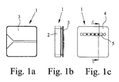
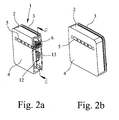
- the electrical connection and junction box according to the preferred embodiment of the invention, a housing 1 with side walls 2 and a lid 3. Furthermore, a bottom 4 of the housing 1 is provided which has an elongate recess 5. As can be seen in particular from FIG. 2 a, a connection device 6 provided in the housing 1 can be reached via this recess 5.
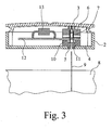
- connection device 6 is formed and arranged in detail, further Fig. 3 can be removed, which shows a section through the electrical connection and junction box according to the preferred embodiment of the invention along the line C-C.
- Fig. 3 is removable, that the connecting device 6 has a clamping device 7 in the form of two counter-acting springs. In this, when you put the electrical connection and junction box according to the preferred embodiment of the invention automatically apparent from Fig. 3 out of the solar cell module 8 led out thin conductor strips 9 introduced.
- a guide device 10 is provided in the housing 1 below the connecting device 6. This has a funnel-shaped in cross section insertion opening 11 which tapers in cross section, so that the conductor strips 9 are guided in the guide device 10 with little play in the transverse direction. In this way, a bending of the conductor strips 9 during insertion into the connecting device 6 is avoided, so that the force acting on the solar cell module when placing the electrical connection and junction box can act virtually completely in the longitudinal direction of the thin conductor strips 9.
- the connecting device 6 is connected to a printed circuit board 12, on which a plurality of bypass diodes 13 is arranged. These bypass diodes 13 have the function described above for securing the individual solar cells and are connected via the connecting device 6 and the thin conductor strips 9 with the individual solar cells of the solar cell module 8.
- the invention goes a completely new way in that the flexible thin conductor strips 9 are inserted not only from below into the housing 1 of the electrical connection and junction box, but also be introduced directly from below into the provided in the housing 1 connecting device 6.
- the connecting device 6 is arranged and designed, in this case in particular namely provided with a guide device 10 that automatically takes place when placing the electrical connection and junction box on the solar cell module 8 an introduction of the conductor strips 9 in the connection device 6.
Landscapes
- Photovoltaic Devices (AREA)
Priority Applications (3)
| Application Number | Priority Date | Filing Date | Title |
|---|---|---|---|
| EP04029825A EP1672702B1 (fr) | 2004-12-16 | 2004-12-16 | Boîte de jonction pour un module de cellule solaire |
| ES04029825T ES2371638T3 (es) | 2004-12-16 | 2004-12-16 | Caja de conexión y unión eléctrica para un módulo de células solares. |
| AT04029825T ATE527694T1 (de) | 2004-12-16 | 2004-12-16 | Elektrische anschluss- und verbindungsdose für ein solarzellenmodul |
Applications Claiming Priority (1)
| Application Number | Priority Date | Filing Date | Title |
|---|---|---|---|
| EP04029825A EP1672702B1 (fr) | 2004-12-16 | 2004-12-16 | Boîte de jonction pour un module de cellule solaire |
Publications (2)
| Publication Number | Publication Date |
|---|---|
| EP1672702A1 true EP1672702A1 (fr) | 2006-06-21 |
| EP1672702B1 EP1672702B1 (fr) | 2011-10-05 |
Family
ID=34927811
Family Applications (1)
| Application Number | Title | Priority Date | Filing Date |
|---|---|---|---|
| EP04029825A Expired - Lifetime EP1672702B1 (fr) | 2004-12-16 | 2004-12-16 | Boîte de jonction pour un module de cellule solaire |
Country Status (3)
| Country | Link |
|---|---|
| EP (1) | EP1672702B1 (fr) |
| AT (1) | ATE527694T1 (fr) |
| ES (1) | ES2371638T3 (fr) |
Cited By (12)
| Publication number | Priority date | Publication date | Assignee | Title |
|---|---|---|---|---|
| WO2008095668A1 (fr) * | 2007-02-05 | 2008-08-14 | Phoenix Contact Gmbh & Co. Kg | Boîtier de raccordement et de connexion pour un module solaire |
| WO2008095670A1 (fr) | 2007-02-05 | 2008-08-14 | Phoenix Contact Gmbh & Co. Kg | Boîtier de raccordement et de connexion pour un module solaire |
| EP1976027A2 (fr) | 2007-03-28 | 2008-10-01 | Günther Spelsberg GmbH & Co. KG | Boîtier de jonction |
| EP1976026A2 (fr) | 2007-03-28 | 2008-10-01 | Günther Spelsberg GmbH & Co. KG | Boîtier de jonction |
| EP1976025A1 (fr) | 2007-03-28 | 2008-10-01 | Günther Spelsberg GmbH | Boîte de panneau |
| DE102007020843A1 (de) | 2007-03-28 | 2008-10-02 | Günther Spelsberg GmbH & Co. KG | Paneldose |
| DE102007020846A1 (de) | 2007-03-28 | 2008-10-09 | Günther Spelsberg GmbH & Co. KG | Paneldose |
| JP2010518564A (ja) * | 2007-02-05 | 2010-05-27 | フェニックス コンタクト ゲーエムベーハー ウント コムパニー カーゲー | 太陽光発電モジュール用接続箱 |
| DE102009030141A1 (de) | 2009-06-24 | 2010-12-30 | A. Raymond Et Cie | Vorrichtung zum elektrischen Kontaktieren von Leiterbändern von Solarmodulen |
| US8435056B2 (en) | 2009-04-16 | 2013-05-07 | Enphase Energy, Inc. | Apparatus for coupling power generated by a photovoltaic module to an output |
| USD734653S1 (en) | 2012-11-09 | 2015-07-21 | Enphase Energy, Inc. | AC module mounting bracket |
| US9118273B2 (en) | 2011-07-18 | 2015-08-25 | Enphase Energy, Inc. | Resilient mounting assembly for photovoltaic modules |
Citations (4)
| Publication number | Priority date | Publication date | Assignee | Title |
|---|---|---|---|---|
| US5503684A (en) * | 1994-12-30 | 1996-04-02 | Silicon Energy Corporation | Termination system for solar panels |
| EP0867947A2 (fr) * | 1997-03-27 | 1998-09-30 | Canon Kabushiki Kaisha | Module de cellules solaires |
| EP1041647A1 (fr) * | 1999-03-30 | 2000-10-04 | Kaneka Corporation | Module photovoltaique et systéme de production d'energie |
| EP1289069A2 (fr) * | 2001-08-27 | 2003-03-05 | Günther Spelsberg GmbH & Co. KG | Bloc de connexions |
-
2004
- 2004-12-16 AT AT04029825T patent/ATE527694T1/de active
- 2004-12-16 ES ES04029825T patent/ES2371638T3/es not_active Expired - Lifetime
- 2004-12-16 EP EP04029825A patent/EP1672702B1/fr not_active Expired - Lifetime
Patent Citations (4)
| Publication number | Priority date | Publication date | Assignee | Title |
|---|---|---|---|---|
| US5503684A (en) * | 1994-12-30 | 1996-04-02 | Silicon Energy Corporation | Termination system for solar panels |
| EP0867947A2 (fr) * | 1997-03-27 | 1998-09-30 | Canon Kabushiki Kaisha | Module de cellules solaires |
| EP1041647A1 (fr) * | 1999-03-30 | 2000-10-04 | Kaneka Corporation | Module photovoltaique et systéme de production d'energie |
| EP1289069A2 (fr) * | 2001-08-27 | 2003-03-05 | Günther Spelsberg GmbH & Co. KG | Bloc de connexions |
Cited By (21)
| Publication number | Priority date | Publication date | Assignee | Title |
|---|---|---|---|---|
| JP2010518564A (ja) * | 2007-02-05 | 2010-05-27 | フェニックス コンタクト ゲーエムベーハー ウント コムパニー カーゲー | 太陽光発電モジュール用接続箱 |
| WO2008095670A1 (fr) | 2007-02-05 | 2008-08-14 | Phoenix Contact Gmbh & Co. Kg | Boîtier de raccordement et de connexion pour un module solaire |
| WO2008095669A1 (fr) * | 2007-02-05 | 2008-08-14 | Phoenix Contact Gmbh & Co. Kg | Boîtier de raccordement et de connexion pour un module solaire |
| US8366471B2 (en) | 2007-02-05 | 2013-02-05 | Phoenix Contact Gmbh & Co. Kg | Connection and junction box for a solar module |
| CN101606294B (zh) * | 2007-02-05 | 2013-01-02 | 菲尼克斯电气公司 | 用于太阳能模块的端子接线箱 |
| WO2008095668A1 (fr) * | 2007-02-05 | 2008-08-14 | Phoenix Contact Gmbh & Co. Kg | Boîtier de raccordement et de connexion pour un module solaire |
| CN101606295B (zh) * | 2007-02-05 | 2012-05-02 | 菲尼克斯电气公司 | 用于太阳能模块的端子接线箱 |
| US8033859B2 (en) | 2007-02-05 | 2011-10-11 | Phoenix Contact Gmbh & Co. Kg | Connection and junction box for a solar module |
| US7931488B2 (en) | 2007-02-05 | 2011-04-26 | Phoenix Contact Gmbh & Co. Kg | Connection and junction box for a solar module |
| EP1976025A1 (fr) | 2007-03-28 | 2008-10-01 | Günther Spelsberg GmbH | Boîte de panneau |
| DE102007020845A1 (de) | 2007-03-28 | 2008-10-09 | Günther Spelsberg GmbH & Co. KG | Paneldose |
| DE102007020846A1 (de) | 2007-03-28 | 2008-10-09 | Günther Spelsberg GmbH & Co. KG | Paneldose |
| US8097818B2 (en) | 2007-03-28 | 2012-01-17 | Gunther Spelsberg Gmbh & Co. Kg | Panel box |
| DE102007020843A1 (de) | 2007-03-28 | 2008-10-02 | Günther Spelsberg GmbH & Co. KG | Paneldose |
| EP1976026A2 (fr) | 2007-03-28 | 2008-10-01 | Günther Spelsberg GmbH & Co. KG | Boîtier de jonction |
| EP1976027A2 (fr) | 2007-03-28 | 2008-10-01 | Günther Spelsberg GmbH & Co. KG | Boîtier de jonction |
| US8435056B2 (en) | 2009-04-16 | 2013-05-07 | Enphase Energy, Inc. | Apparatus for coupling power generated by a photovoltaic module to an output |
| DE102009030141A1 (de) | 2009-06-24 | 2010-12-30 | A. Raymond Et Cie | Vorrichtung zum elektrischen Kontaktieren von Leiterbändern von Solarmodulen |
| US9118273B2 (en) | 2011-07-18 | 2015-08-25 | Enphase Energy, Inc. | Resilient mounting assembly for photovoltaic modules |
| US11515835B2 (en) | 2011-07-18 | 2022-11-29 | Enphase Energy, Inc. | Resilient mounting assembly for photovoltaic modules |
| USD734653S1 (en) | 2012-11-09 | 2015-07-21 | Enphase Energy, Inc. | AC module mounting bracket |
Also Published As
| Publication number | Publication date |
|---|---|
| EP1672702B1 (fr) | 2011-10-05 |
| ES2371638T3 (es) | 2012-01-05 |
| ATE527694T1 (de) | 2011-10-15 |
Similar Documents
| Publication | Publication Date | Title |
|---|---|---|
| DE10358140B4 (de) | Elektrische Anschluß- und Verbindungsdose für ein Solarzellenmodul | |
| EP1729348B1 (fr) | Boîte de jonction pour un module de cellule solaire | |
| DE102008003448B4 (de) | Anschlußdose, Verwendung, Solarpaneel, Kontaktelement, und Verfahren | |
| EP1672702B1 (fr) | Boîte de jonction pour un module de cellule solaire | |
| DE102007020843A1 (de) | Paneldose | |
| EP3047540B1 (fr) | Cage de serrage pour bloc de jonction à insertion directe | |
| DE102008010026A1 (de) | Elektrische Anschluss- und Verbindungsdose für ein Solarzellenmodul | |
| DE202007001701U1 (de) | Universalkontakt | |
| WO2007118798A2 (fr) | Dispositif de connexion électrique pour conducteur plat | |
| DE102007043178A1 (de) | Anschlußdose, Solarpaneel, Kontaktvorrichtung und Verfahren | |
| DE102012206731A1 (de) | Anschlussvorrichtung für ein Solarmodul | |
| DE102010013002A1 (de) | Batterie mit einem Zellenstapel | |
| EP1496577B1 (fr) | Boîtier de terminaison et de jonction électrique | |
| DE102018202542A1 (de) | Klemme | |
| DE112014001321T5 (de) | Elektronikkomponenten-Anordnungsaufbau und elektrischer Anschlusskasten | |
| WO2008095453A1 (fr) | Appareil électrique et agencement d'appareil | |
| DE102011052928A1 (de) | Anordnung mit einem Solarzellenmodul, einer Anschlussdose, einem Anschlussstecker und einer Anschlussleitung | |
| DE19963268B4 (de) | Sicherungsleiste, zugehöriger Sicherungskasten und Herstellungsverfahren | |
| EP2056357A2 (fr) | Agencement doté d'un module de cellule solaire et d'un cadre | |
| EP1976026A2 (fr) | Boîtier de jonction | |
| DE102007020846A1 (de) | Paneldose | |
| DE102007020845B4 (de) | Paneldose | |
| DE1919169U (de) | Vorrichtung zur verbindung und zum festklemmen von elektrischen leitern. | |
| DE102017112548A1 (de) | Elektrische kontakteinrichtung und metallische aufnahme für eine elektrische kontakteinrichtung | |
| DE19944427A1 (de) | Kabelverbindung zwischen Flachbandkabel und Rundbandkabel bzw. Rundkabel und Verfahren zu deren Herstellung |
Legal Events
| Date | Code | Title | Description |
|---|---|---|---|
| PUAI | Public reference made under article 153(3) epc to a published international application that has entered the european phase |
Free format text: ORIGINAL CODE: 0009012 |
|
| AK | Designated contracting states |
Kind code of ref document: A1 Designated state(s): AT BE BG CH CY CZ DE DK EE ES FI FR GB GR HU IE IS IT LI LT LU MC NL PL PT RO SE SI SK TR |
|
| AX | Request for extension of the european patent |
Extension state: AL BA HR LV MK YU |
|
| 17P | Request for examination filed |
Effective date: 20061005 |
|
| AKX | Designation fees paid |
Designated state(s): AT BE BG CH CY CZ DE DK EE ES FI FR GB GR HU IE IS IT LI LT LU MC NL PL PT RO SE SI SK TR |
|
| 17Q | First examination report despatched |
Effective date: 20070309 |
|
| GRAP | Despatch of communication of intention to grant a patent |
Free format text: ORIGINAL CODE: EPIDOSNIGR1 |
|
| GRAS | Grant fee paid |
Free format text: ORIGINAL CODE: EPIDOSNIGR3 |
|
| GRAA | (expected) grant |
Free format text: ORIGINAL CODE: 0009210 |
|
| RIN1 | Information on inventor provided before grant (corrected) |
Inventor name: NIELECK, UDO Inventor name: QUARDT, DIRK, DIPL.-ING. Inventor name: ZBOROWSKI, ZBIGNIEW, DIPL.-ING. Inventor name: WASSERFUHR, FRIEDEL, DIPL.-ING. |
|
| AK | Designated contracting states |
Kind code of ref document: B1 Designated state(s): AT BE BG CH CY CZ DE DK EE ES FI FR GB GR HU IE IS IT LI LT LU MC NL PL PT RO SE SI SK TR |
|
| REG | Reference to a national code |
Ref country code: GB Ref legal event code: FG4D Free format text: NOT ENGLISH |
|
| REG | Reference to a national code |
Ref country code: CH Ref legal event code: EP |
|
| REG | Reference to a national code |
Ref country code: IE Ref legal event code: FG4D |
|
| REG | Reference to a national code |
Ref country code: DE Ref legal event code: R096 Ref document number: 502004012928 Country of ref document: DE Effective date: 20111229 |
|
| REG | Reference to a national code |
Ref country code: ES Ref legal event code: FG2A Ref document number: 2371638 Country of ref document: ES Kind code of ref document: T3 Effective date: 20120105 |
|
| REG | Reference to a national code |
Ref country code: NL Ref legal event code: VDEP Effective date: 20111005 |
|
| PGFP | Annual fee paid to national office [announced via postgrant information from national office to epo] |
Ref country code: CH Payment date: 20111227 Year of fee payment: 8 |
|
| PG25 | Lapsed in a contracting state [announced via postgrant information from national office to epo] |
Ref country code: SI Free format text: LAPSE BECAUSE OF FAILURE TO SUBMIT A TRANSLATION OF THE DESCRIPTION OR TO PAY THE FEE WITHIN THE PRESCRIBED TIME-LIMIT Effective date: 20111005 |
|
| LTIE | Lt: invalidation of european patent or patent extension |
Effective date: 20111005 |
|
| REG | Reference to a national code |
Ref country code: GR Ref legal event code: EP Ref document number: 20110403053 Country of ref document: GR Effective date: 20120206 |
|
| PG25 | Lapsed in a contracting state [announced via postgrant information from national office to epo] |
Ref country code: IS Free format text: LAPSE BECAUSE OF FAILURE TO SUBMIT A TRANSLATION OF THE DESCRIPTION OR TO PAY THE FEE WITHIN THE PRESCRIBED TIME-LIMIT Effective date: 20120205 Ref country code: LT Free format text: LAPSE BECAUSE OF FAILURE TO SUBMIT A TRANSLATION OF THE DESCRIPTION OR TO PAY THE FEE WITHIN THE PRESCRIBED TIME-LIMIT Effective date: 20111005 |
|
| REG | Reference to a national code |
Ref country code: IE Ref legal event code: FD4D |
|
| PG25 | Lapsed in a contracting state [announced via postgrant information from national office to epo] |
Ref country code: NL Free format text: LAPSE BECAUSE OF FAILURE TO SUBMIT A TRANSLATION OF THE DESCRIPTION OR TO PAY THE FEE WITHIN THE PRESCRIBED TIME-LIMIT Effective date: 20111005 Ref country code: PT Free format text: LAPSE BECAUSE OF FAILURE TO SUBMIT A TRANSLATION OF THE DESCRIPTION OR TO PAY THE FEE WITHIN THE PRESCRIBED TIME-LIMIT Effective date: 20120206 Ref country code: SE Free format text: LAPSE BECAUSE OF FAILURE TO SUBMIT A TRANSLATION OF THE DESCRIPTION OR TO PAY THE FEE WITHIN THE PRESCRIBED TIME-LIMIT Effective date: 20111005 |
|
| PG25 | Lapsed in a contracting state [announced via postgrant information from national office to epo] |
Ref country code: CY Free format text: LAPSE BECAUSE OF FAILURE TO SUBMIT A TRANSLATION OF THE DESCRIPTION OR TO PAY THE FEE WITHIN THE PRESCRIBED TIME-LIMIT Effective date: 20111005 |
|
| BERE | Be: lapsed |
Owner name: GUNTHER SPELSBERG G.M.B.H. & CO. KG Effective date: 20111231 |
|
| PG25 | Lapsed in a contracting state [announced via postgrant information from national office to epo] |
Ref country code: CZ Free format text: LAPSE BECAUSE OF FAILURE TO SUBMIT A TRANSLATION OF THE DESCRIPTION OR TO PAY THE FEE WITHIN THE PRESCRIBED TIME-LIMIT Effective date: 20111005 Ref country code: SK Free format text: LAPSE BECAUSE OF FAILURE TO SUBMIT A TRANSLATION OF THE DESCRIPTION OR TO PAY THE FEE WITHIN THE PRESCRIBED TIME-LIMIT Effective date: 20111005 Ref country code: BG Free format text: LAPSE BECAUSE OF FAILURE TO SUBMIT A TRANSLATION OF THE DESCRIPTION OR TO PAY THE FEE WITHIN THE PRESCRIBED TIME-LIMIT Effective date: 20120105 Ref country code: DK Free format text: LAPSE BECAUSE OF FAILURE TO SUBMIT A TRANSLATION OF THE DESCRIPTION OR TO PAY THE FEE WITHIN THE PRESCRIBED TIME-LIMIT Effective date: 20111005 Ref country code: IE Free format text: LAPSE BECAUSE OF FAILURE TO SUBMIT A TRANSLATION OF THE DESCRIPTION OR TO PAY THE FEE WITHIN THE PRESCRIBED TIME-LIMIT Effective date: 20111005 Ref country code: MC Free format text: LAPSE BECAUSE OF NON-PAYMENT OF DUE FEES Effective date: 20111231 Ref country code: EE Free format text: LAPSE BECAUSE OF FAILURE TO SUBMIT A TRANSLATION OF THE DESCRIPTION OR TO PAY THE FEE WITHIN THE PRESCRIBED TIME-LIMIT Effective date: 20111005 |
|
| PLBE | No opposition filed within time limit |
Free format text: ORIGINAL CODE: 0009261 |
|
| STAA | Information on the status of an ep patent application or granted ep patent |
Free format text: STATUS: NO OPPOSITION FILED WITHIN TIME LIMIT |
|
| PG25 | Lapsed in a contracting state [announced via postgrant information from national office to epo] |
Ref country code: RO Free format text: LAPSE BECAUSE OF FAILURE TO SUBMIT A TRANSLATION OF THE DESCRIPTION OR TO PAY THE FEE WITHIN THE PRESCRIBED TIME-LIMIT Effective date: 20111005 Ref country code: PL Free format text: LAPSE BECAUSE OF FAILURE TO SUBMIT A TRANSLATION OF THE DESCRIPTION OR TO PAY THE FEE WITHIN THE PRESCRIBED TIME-LIMIT Effective date: 20111005 |
|
| 26N | No opposition filed |
Effective date: 20120706 |
|
| GBPC | Gb: european patent ceased through non-payment of renewal fee |
Effective date: 20120105 |
|
| PG25 | Lapsed in a contracting state [announced via postgrant information from national office to epo] |
Ref country code: GB Free format text: LAPSE BECAUSE OF NON-PAYMENT OF DUE FEES Effective date: 20120105 Ref country code: BE Free format text: LAPSE BECAUSE OF NON-PAYMENT OF DUE FEES Effective date: 20111231 |
|
| REG | Reference to a national code |
Ref country code: DE Ref legal event code: R097 Ref document number: 502004012928 Country of ref document: DE Effective date: 20120706 |
|
| PG25 | Lapsed in a contracting state [announced via postgrant information from national office to epo] |
Ref country code: LU Free format text: LAPSE BECAUSE OF NON-PAYMENT OF DUE FEES Effective date: 20111216 |
|
| PG25 | Lapsed in a contracting state [announced via postgrant information from national office to epo] |
Ref country code: FI Free format text: LAPSE BECAUSE OF FAILURE TO SUBMIT A TRANSLATION OF THE DESCRIPTION OR TO PAY THE FEE WITHIN THE PRESCRIBED TIME-LIMIT Effective date: 20111005 |
|
| REG | Reference to a national code |
Ref country code: CH Ref legal event code: PL |
|
| REG | Reference to a national code |
Ref country code: AT Ref legal event code: MM01 Ref document number: 527694 Country of ref document: AT Kind code of ref document: T Effective date: 20121216 |
|
| REG | Reference to a national code |
Ref country code: GR Ref legal event code: ML Ref document number: 20110403053 Country of ref document: GR Effective date: 20130703 |
|
| PG25 | Lapsed in a contracting state [announced via postgrant information from national office to epo] |
Ref country code: TR Free format text: LAPSE BECAUSE OF FAILURE TO SUBMIT A TRANSLATION OF THE DESCRIPTION OR TO PAY THE FEE WITHIN THE PRESCRIBED TIME-LIMIT Effective date: 20111005 |
|
| PG25 | Lapsed in a contracting state [announced via postgrant information from national office to epo] |
Ref country code: AT Free format text: LAPSE BECAUSE OF NON-PAYMENT OF DUE FEES Effective date: 20121216 Ref country code: CH Free format text: LAPSE BECAUSE OF NON-PAYMENT OF DUE FEES Effective date: 20121231 Ref country code: LI Free format text: LAPSE BECAUSE OF NON-PAYMENT OF DUE FEES Effective date: 20121231 Ref country code: GR Free format text: LAPSE BECAUSE OF NON-PAYMENT OF DUE FEES Effective date: 20130703 Ref country code: HU Free format text: LAPSE BECAUSE OF FAILURE TO SUBMIT A TRANSLATION OF THE DESCRIPTION OR TO PAY THE FEE WITHIN THE PRESCRIBED TIME-LIMIT Effective date: 20111005 |
|
| PG25 | Lapsed in a contracting state [announced via postgrant information from national office to epo] |
Ref country code: IT Free format text: LAPSE BECAUSE OF NON-PAYMENT OF DUE FEES Effective date: 20121216 |
|
| REG | Reference to a national code |
Ref country code: FR Ref legal event code: PLFP Year of fee payment: 12 |
|
| REG | Reference to a national code |
Ref country code: FR Ref legal event code: PLFP Year of fee payment: 13 |
|
| REG | Reference to a national code |
Ref country code: FR Ref legal event code: PLFP Year of fee payment: 14 |
|
| PGFP | Annual fee paid to national office [announced via postgrant information from national office to epo] |
Ref country code: ES Payment date: 20190124 Year of fee payment: 15 |
|
| PGFP | Annual fee paid to national office [announced via postgrant information from national office to epo] |
Ref country code: FR Payment date: 20191219 Year of fee payment: 16 |
|
| PGFP | Annual fee paid to national office [announced via postgrant information from national office to epo] |
Ref country code: DE Payment date: 20191218 Year of fee payment: 16 |
|
| REG | Reference to a national code |
Ref country code: ES Ref legal event code: FD2A Effective date: 20210601 |
|
| REG | Reference to a national code |
Ref country code: DE Ref legal event code: R119 Ref document number: 502004012928 Country of ref document: DE |
|
| PG25 | Lapsed in a contracting state [announced via postgrant information from national office to epo] |
Ref country code: ES Free format text: LAPSE BECAUSE OF NON-PAYMENT OF DUE FEES Effective date: 20191217 |
|
| PG25 | Lapsed in a contracting state [announced via postgrant information from national office to epo] |
Ref country code: FR Free format text: LAPSE BECAUSE OF NON-PAYMENT OF DUE FEES Effective date: 20201231 |
|
| PG25 | Lapsed in a contracting state [announced via postgrant information from national office to epo] |
Ref country code: DE Free format text: LAPSE BECAUSE OF NON-PAYMENT OF DUE FEES Effective date: 20210701 |