EP1673136B1 - Gerät zur verpackung einer elektrode - Google Patents
Gerät zur verpackung einer elektrode Download PDFInfo
- Publication number
- EP1673136B1 EP1673136B1 EP04769955A EP04769955A EP1673136B1 EP 1673136 B1 EP1673136 B1 EP 1673136B1 EP 04769955 A EP04769955 A EP 04769955A EP 04769955 A EP04769955 A EP 04769955A EP 1673136 B1 EP1673136 B1 EP 1673136B1
- Authority
- EP
- European Patent Office
- Prior art keywords
- electrode
- connector
- medical
- flexible material
- enclosure
- Prior art date
- Legal status (The legal status is an assumption and is not a legal conclusion. Google has not performed a legal analysis and makes no representation as to the accuracy of the status listed.)
- Expired - Lifetime
Links
- 238000004806 packaging method and process Methods 0.000 title abstract description 10
- 239000000463 material Substances 0.000 claims abstract description 43
- 238000004891 communication Methods 0.000 claims description 10
- 230000008878 coupling Effects 0.000 claims 1
- 238000010168 coupling process Methods 0.000 claims 1
- 238000005859 coupling reaction Methods 0.000 claims 1
- 238000007789 sealing Methods 0.000 abstract description 13
- 239000004020 conductor Substances 0.000 abstract description 12
- 238000001827 electrotherapy Methods 0.000 description 11
- 239000010410 layer Substances 0.000 description 9
- 238000003860 storage Methods 0.000 description 7
- 230000004888 barrier function Effects 0.000 description 3
- 238000004519 manufacturing process Methods 0.000 description 3
- 238000012544 monitoring process Methods 0.000 description 3
- -1 or a rigid Substances 0.000 description 3
- 238000010586 diagram Methods 0.000 description 2
- 239000000499 gel Substances 0.000 description 2
- 239000002648 laminated material Substances 0.000 description 2
- 238000000034 method Methods 0.000 description 2
- 239000002991 molded plastic Substances 0.000 description 2
- 239000004033 plastic Substances 0.000 description 2
- 229920003023 plastic Polymers 0.000 description 2
- 238000002560 therapeutic procedure Methods 0.000 description 2
- 239000004831 Hot glue Substances 0.000 description 1
- 239000004698 Polyethylene Substances 0.000 description 1
- 239000004743 Polypropylene Substances 0.000 description 1
- 239000002390 adhesive tape Substances 0.000 description 1
- XAGFODPZIPBFFR-UHFFFAOYSA-N aluminium Chemical compound [Al] XAGFODPZIPBFFR-UHFFFAOYSA-N 0.000 description 1
- 229910052782 aluminium Inorganic materials 0.000 description 1
- 230000000747 cardiac effect Effects 0.000 description 1
- 230000001010 compromised effect Effects 0.000 description 1
- 230000001419 dependent effect Effects 0.000 description 1
- 230000007613 environmental effect Effects 0.000 description 1
- 239000011888 foil Substances 0.000 description 1
- 230000006870 function Effects 0.000 description 1
- 239000012793 heat-sealing layer Substances 0.000 description 1
- 239000000017 hydrogel Substances 0.000 description 1
- 230000036512 infertility Effects 0.000 description 1
- 229920001684 low density polyethylene Polymers 0.000 description 1
- 239000004702 low-density polyethylene Substances 0.000 description 1
- 230000015654 memory Effects 0.000 description 1
- 239000012811 non-conductive material Substances 0.000 description 1
- 230000000737 periodic effect Effects 0.000 description 1
- JTJMJGYZQZDUJJ-UHFFFAOYSA-N phencyclidine Chemical compound C1CCCCN1C1(C=2C=CC=CC=2)CCCCC1 JTJMJGYZQZDUJJ-UHFFFAOYSA-N 0.000 description 1
- 229920000573 polyethylene Polymers 0.000 description 1
- 229920001155 polypropylene Polymers 0.000 description 1
- XLYOFNOQVPJJNP-UHFFFAOYSA-N water Substances O XLYOFNOQVPJJNP-UHFFFAOYSA-N 0.000 description 1
- 238000003466 welding Methods 0.000 description 1
Images
Classifications
-
- A—HUMAN NECESSITIES
- A61—MEDICAL OR VETERINARY SCIENCE; HYGIENE
- A61N—ELECTROTHERAPY; MAGNETOTHERAPY; RADIATION THERAPY; ULTRASOUND THERAPY
- A61N1/00—Electrotherapy; Circuits therefor
- A61N1/02—Details
- A61N1/04—Electrodes
- A61N1/0404—Electrodes for external use
- A61N1/0472—Structure-related aspects
-
- A—HUMAN NECESSITIES
- A61—MEDICAL OR VETERINARY SCIENCE; HYGIENE
- A61N—ELECTROTHERAPY; MAGNETOTHERAPY; RADIATION THERAPY; ULTRASOUND THERAPY
- A61N1/00—Electrotherapy; Circuits therefor
- A61N1/02—Details
- A61N1/04—Electrodes
- A61N1/0404—Electrodes for external use
- A61N1/0408—Use-related aspects
- A61N1/046—Specially adapted for shock therapy, e.g. defibrillation
Definitions
- aspects of this invention relate generally to electrode storage, and more particularly to an apparatus and method for packaging a medical electrode, and to an electrotherapy device having an electrode.
- Electrode packaging provides a sealed electrode storage environment and through-wall electrical connectivity to electrotherapy devices such as external defibrillators.
- Most modem electrodes use a water-based gel to adhere the electrode to the skin and to provide a good conductive path between skin and electrode. Because the hydrogels tend to gradually dry out and become ineffective, sealing of the electrode from the environment extends the shelf-life of the electrode significantly.
- electrode packaging is typically either a flexible, heat-sealable laminate material, or a rigid, molded plastic material, which serves as a moisture barrier.
- Electrode wiresets extend through exteriors of known flexible housings, and connect directly to electrotherapy devices. Electrode function or sterility, however, may be compromised when electrode wiresets protrude through flexible housings--for example, flexing may weaken the bond between the electrode wireset and the flexible material, and/or the flexible material may remain adhered to electrode wiresets after placement of electrodes on a patient, causing user confusion or delay. Adequately sealing areas where electrode wiresets extending through flexible housings may increase manufacturing costs or complexity.
- Rigid structures offer an alternative to flexible housings. Walls of rigid structures may include insert-molded electrical contacts, such as pins, which provide through-wall electrical connectivity between enclosed electrode wiresets and external electrotherapy devices. Although rigid housing structures may sometimes be more expensive and have higher manufacturing costs than flexible housings, rigid structures are often selected because they have been designed to enclose electrode wiresets without compromising the structures' seals, and they offer simple user interfaces. Rigid structures, however, may be less desirable in some applications at high altitudes, when pressures inside the structures greatly exceed ambient pressures, and heat-seal film, which is often stretched over structure openings, may be vulnerable to puncture.
- WO 03/037176 A1 an enclosure for a medical electrode which seals the medical electrode against moisture loss while the medical electrode remains in electrical communication with a medical instrument is known.
- This enclosure comprises a wall of flexible material and a connector in this wall, wherein the connector is adapted to connect to the medical instrument and to the medical electrode, respectively.
- a sealed package system for housing at least one medical electrode apparatus and for enabling periodic testing thereof is known.
- the package comprises a thin, generally flat flexible envelope constructed and arranged to form an interior cavity for enclosing a conductive gel contact surface of an electrode apparatus-
- the envelope has one continuous layer of a homogeneous, non-conductive, polymeric material.
- a structure for conducting current across the envelope to the interior cavity is provided, wherein the conductive structure is electrically connectible to the electrode conductive contact surface.
- an apparatus for packaging a medical electrode having an electrode wireset comprises a flexible electrode wireset package having an interior connector on the inside of the package which is connected through the package to an exterior connector on the outside of the package.
- An electrode wireset can be sealed in the package with the electrode connector connected to the interior connector in the inside of the package.
- the exterior connector on the outside of the package is connected to an instrument such as a patient monitor or electrotherapy device
- the electrode wireset which is sealed inside the package is in electrical communication with the instrument for testing or other analysis.
- the electrode is put to use, the package is opened and the electrode can be immediately applied to the patient with no change in connections. That is, the electrode can remain connected to the instrument through the package connectors while in use.
- the electrode wireset can be unplugged from the interior package connector and plugged directly into the instrument, with the package placed away from the treatment area.
- a further benefit of the present invention is that the packaged electrode can be removed from the instrument and replaced with another electrode without the need to open the sealed package. Another benefit is that the electrode can be used on a different instrument by unplugging the exterior connector from the instrument and reconnecting it to a different instrument. Yet another benefit is the ability to open the package and unplug and remove the electrode from the package, then be able to immediately use the electrode with a different instrument if desired.
- the interior and exterior connectors are attached to and electrically connected through a rigid plastic flange which can be readily heat-sealed in an opening in the wall of a flexible pouch package.
- This embodiment obviates the need to try to seal the seam of the package around the wires or connector of an electrode, which is prone to leakage and seal failure.
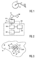
- FIG. 1 illustrates basic functional elements of a medical electrode 12, which may be packaged in accordance with certain aspects of the present invention.
- Electrode 12 includes a patient portion 13, a wireset 14 coupled to patient portion 13, and a detachably connectable electrode adapter 16 coupled to wireset 14.
- Electrode 12 may be used with an electrotherapy system, such as an automatic or manual external defibrillator system, or another type of electrotherapy system, such as pacing or cardiac monitoring systems.
- FIG. 2 A schematic block diagram of an external defibrillator system 200 that uses electrode 12 is depicted in FIG. 2 .
- Defibrillator system 200 includes an energy source 202, which provides voltage or current pulses.
- a controller 204 operates an energy delivery system 206 to selectively connect and disconnect energy source 202 to and from one or more electrodes 12 electrically attachable to a patient 208.
- Defibrillator system 200 may further include elements (not shown) such as user input and/or output devices or displays, memories, or computer-executable instructions implemented in software, firmware, hardware or a combination thereof.
- Electrode interface 210 includes, at least in part, areas for receiving electrode adapter 16 and an energy delivery connector 211 (which may be, for example, an electrical plug), and further includes apparatus 10 configured in accordance with aspects of the present invention (discussed further below).
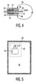
- Apparatus 10 is shown in partial perspective view in FIG. 3 , and in more detail in cross-sectional side view along line IV-IV in FIG. 4 .
- apparatus 10 is adapted for use with a heat-sealable flexible material 32, which has an interior side 34 (shown in cut-away view in FIG. 3 ) and an exterior side 36 (not visible; shown in FIG. 5 and discussed further below.)
- Material 32 is preferably arranged in laminate form, having at least three layers.
- a top layer is comprised of a non-conductive material with good printability such as polypropylene.
- a second layer is comprised of a moisture barrier, such as aluminum foil and/or low-density polyethylene.
- a bottom layer is comprised of a heat-sealable material such as polyethylene.
- a heat-sealable flexible laminate material 32 suitable for use with apparatus 10 is commercially available from Cadillac Products, Incorporated in Troy Michigan. Material 32 could alternatively be comprised of two layers, including a moisture barrier layer and a heat-sealing layer. The layers may also be arranged in a different order.
- apparatus 10 includes a housing 20 having two sides.
- a first housing side 18 defines an electrode connection region 28, which is sized to receive at least a portion of electrode 12, such as electrode adapter 16.
- a second housing side 19 defines a medical device connection region 29, which is sized to receive at least a part of a medical device, such as energy delivery connector 211 from defibrillator system 200 (shown in FIG. 2 ).
- housing sides 18, 19 have partially open polyhedrous configurations, although housing sides 18 and 19 may assume any desired geometric configurations.
- Housing 20 is preferably an integral, molded plastic device, but may be formed of a plurality of interconnected parts of any suitable material.
- a sealing surface 22 having two sides 24, 26 is coupled to housing 20. As shown, sealing surface side 24 is coupled to first housing side 18, and sealing surface side 26 is coupled to second housing side 19. Sealing surface 22 also has an attachment area 23, for attaching sealing surface 22 to one or more laminate layers of heat-sealable flexible material 32 (shown in FIG. 3 ). Attachment area 23 preferably extends outside of a perimeter of housing 20, but may be interposed between housing sides 18, 19. Sealing surface 22 is preferably a planar plastic flange, integrally formed with housing 20, but may be constructed separately from housing 20 and attached thereto in any suitable fashion.
- Signal conductor 27 is preferably an electrical conductor, such as a pin connector, insert-molded into housing 20, but may be any device now known or later developed capable of causing electrical signals, or representations thereof, to traverse heat-sealable flexible material 32.
- Signal conductor 27 may be disposed in housing sides 18, 19, heat-sealable flexible material 32, and/or sealing surface 22.
- FIG. 5 depicts apparatus 10 in use with heat-sealable flexible material 32, in accordance with certain aspects of the present invention.
- side 19 of housing 20 is disposed on exterior 36 of heat-sealable flexible material 32.
- Two signal conductors 27 are arranged in medical device connection region 31 (partially visible).
- Housing side 18 (not visible) is disposed on interior 34 (also not visible) of heat-sealable flexible material 32.
- Apparatus 10 is preferably inserted into a keyed, die-cut hole in material 32, and housing 20 is preferably attached to material 32 by heat-sealing sealing surface 22 to one or more surface(s) of laminates defining interior 34 and/or exterior 36 of material 32. Sealing surface 22, however, may also be attached in other way-by application of hot-melt adhesive or double-sided adhesive tape, or ultrasonic welding, for example.
- a zone 38 preferably on a perimeter of material 32, is heat-sealable to form a container for storage of electrode 12.
- material 32 may be folded and sealed at zone 38, to form a sealed pouch-type container, with interior 34 forming the inside of the container Apparatus 10 may be automatically inserted in material 32 before pouches are formed, at the sheet-stock stage, or may be installed after storage pouches or containers are formed from material 32.
- Electrodes 12 may be arranged in electrode connection region 18, in such a manner as to be responsive to end 30.
- signal conductor 27 is an electrical connector, such as a pin
- electrode adapter 16 may be detachably coupled to the pin.
- Patient portion 13 and wireset 14 are preferably disposed relative to side 34 of material 32-preferably enclosed in a container formed at least in part by interior 34. The container may be hermetically sealed for electrode storage or transport.
- Electrode 12 may be established via apparatus 10 when a portion of a medical device, such as energy delivery connector 211, is arranged in medical device connection region 19 and coupled to one more signal conductors 27.
- a medical device such as energy delivery connector 211
- an electrode 12 is packaged in accordance with aspects of the present invention, and when the medical device is coupled to signal conductors in region 31, in such a manner that the signal path traversing material 32 is operational, electrode 12 remains responsive to the medical device during shipping, storage or use.
- communication may be established between packaged electrode 12 and a medical device for purposes of testing the functionality of electrode 12 while the medical device is in standby mode, and the medical device and/or electrode 12 may be enabled to alarm if a problem is detected.
- communication between packaged electrode 12 and the medical device may be used to monitor other parameters of interest, such as interior environmental conditions of electrode 12, or packaging thereof. Additional connections, such as signal conductors 27, could be used to facilitate monitoring such additional parameters.
- apparatus 10 may provide communication between the medical device and packaged electrode 12 during normal operation of the medical device in connection with patient therapy.
- electrode 12 may be placed patient 208 without detachment of electrode adapter 16 from apparatus 10, and defibrillator 200, may continue to provide/receive electrical communication and information to/from electrode 12 via apparatus 10 during patient treatment and monitoring, without further user intervention.
- electrode adapter 16 when electrode adapter 16 is detached from apparatus 10, electrode adapter 16 may be re-attached to apparatus 10, or may be attached directly to another device, such as another electrotherapy device (not shown) for use in care of patient 208.
- another electrotherapy device not shown
- apparatus 10 provides flexible manufacturing/assembly, a simple user interface that reduces set-up time to a minimum, and usability with heat-sealable flexible materials that enclose electrode wiresets without compromising enclosure seals. Electrodes packaged using apparatus 10 remain responsive to electrotherapy devices, and may be monitored for functionality and used for patient therapy without interruption of connection from the electrotherapy device.
Landscapes
- Health & Medical Sciences (AREA)
- Animal Behavior & Ethology (AREA)
- Public Health (AREA)
- Nuclear Medicine, Radiotherapy & Molecular Imaging (AREA)
- Radiology & Medical Imaging (AREA)
- Life Sciences & Earth Sciences (AREA)
- Engineering & Computer Science (AREA)
- General Health & Medical Sciences (AREA)
- Biomedical Technology (AREA)
- Veterinary Medicine (AREA)
- Electrotherapy Devices (AREA)
- Package Closures (AREA)
- Electrical Discharge Machining, Electrochemical Machining, And Combined Machining (AREA)
- Electrodes Of Semiconductors (AREA)
- Liquid Crystal (AREA)
Claims (7)
- Gehäuse für eine medizinische Elektrode (12), das die medizinische Elektrode (12) gegen Feuchtigkeitsverlust abdichtet, während die medizinische Elektrode (12) in elektrischer Kommunikation mit einem medizinischen Instrument (200) bleibt, wobei das Gehäuse Folgendes umfasst:eine Wand aus biegbarem Material (32), die ein Gehäuse bildet und dafür vorgesehen ist, gegen Feuchtigkeitsverlust abzudichten;einen internen Steckverbinder (30), der sich auf der Innenseite (34) der Wand aus biegbarem Material (32) befindet und für die Verbindung mit der medizinischen Elektrode (12) ausgelegt ist; undeinen externen Steckverbinder (31), der sich auf der Außenseite (36) der Wand aus biegbarem Material (32) befindet und für die Verbindung mit dem medizinischen Instrument (200) vorgesehen ist, wobei der externe Steckverbinder (31) in elektrischer Kommunikation mit dem internen Steckverbinder (30) steht,dadurch gekennzeichnet, dassein Flansch (22) vorgesehen ist, bei dem der interne Steckverbinder (30) und der externe Steckverbinder (31) auf gegenüberliegenden Seiten angeordnet sind,der interne Steckverbinder (30) und der externe Steckverbinder (31) durch ein Loch in der Wand aus biegbarem Material versiegelt sind:der Flansch (22) mit dem Loch in der Wand aus biegbarem Material (32) versiegelt ist, undder Flansch (22) aus einem starren, isolierenden Material gebildet ist.
- Gehäuse nach Anspruch 1, wobei die medizinische Elektrode (12) einen Kabelsatz (14) umfasst, der mit dem internen Steckverbinder (30) gekoppelt ist, wobei die medizinische Elektrode (12) im Inneren des Gehäuses versiegelt ist.
- Gehäuse nach Anspruch 2, wobei der externe Steckverbinder (31) zur Kopplung des medizinischen Instruments (200) in elektrischer Verbindung mit der medizinischen Elektrode (12) vorgesehen ist.
- Gehäuse nach einem der Ansprüche 1 bis 3, wobei der Flansch (22) aus Heißsiegelmaterial gebildet ist.
- Gehäuse nach Anspruch 4, wobei der Flansch (22) mit der Peripherie des Lochs in der Wand aus biegbarem Material (32) heißversiegelt ist.
- Gehäuse nach einem der Ansprüche 1 bis 5, wobei die Wand aus biegbarem Material (12) eine hermetisch versiegelbare Tasche zur Aufbewahrung der medizinischen Elektrode (12) umfasst.
- Gehäuse nach einem der Ansprüche 1 bis 6, wobei der interne Steckverbinder (30) und der externe Steckverbinder (31) einen elektrischen Steckverbinder umfassen, dessen erstes Ende im Inneren des Gehäuses angeordnet ist und dessen zweites Ende auf der Außenseite des Gehäuses angeordnet ist.
Applications Claiming Priority (2)
| Application Number | Priority Date | Filing Date | Title |
|---|---|---|---|
| US50901103P | 2003-10-06 | 2003-10-06 | |
| PCT/IB2004/051705 WO2005032648A1 (en) | 2003-10-06 | 2004-09-07 | Apparatus and method for packaging an electrode |
Publications (2)
| Publication Number | Publication Date |
|---|---|
| EP1673136A1 EP1673136A1 (de) | 2006-06-28 |
| EP1673136B1 true EP1673136B1 (de) | 2008-06-11 |
Family
ID=34421797
Family Applications (1)
| Application Number | Title | Priority Date | Filing Date |
|---|---|---|---|
| EP04769955A Expired - Lifetime EP1673136B1 (de) | 2003-10-06 | 2004-09-07 | Gerät zur verpackung einer elektrode |
Country Status (6)
| Country | Link |
|---|---|
| US (1) | US20070038281A1 (de) |
| EP (1) | EP1673136B1 (de) |
| JP (1) | JP2007507273A (de) |
| AT (1) | ATE397956T1 (de) |
| DE (1) | DE602004014394D1 (de) |
| WO (1) | WO2005032648A1 (de) |
Families Citing this family (2)
| Publication number | Priority date | Publication date | Assignee | Title |
|---|---|---|---|---|
| JP4706969B2 (ja) * | 2006-02-08 | 2011-06-22 | 日本光電工業株式会社 | 生体用電極ユニット包装体およびその良否判定検査方法 |
| US12109407B2 (en) | 2018-01-11 | 2024-10-08 | Theranica Bio-Electronics Ltd. | Electrode patch |
Family Cites Families (7)
| Publication number | Priority date | Publication date | Assignee | Title |
|---|---|---|---|---|
| US5402884A (en) * | 1992-09-24 | 1995-04-04 | Surviva Link Corporation | Medical electrode packaging technology |
| US5462157A (en) * | 1993-10-28 | 1995-10-31 | Zmd Corporation | Electrode package |
| US5697955A (en) * | 1996-05-10 | 1997-12-16 | Survivalink Corporation | Defibrillator electrodes and date code detector circuit |
| US6101413A (en) * | 1996-06-04 | 2000-08-08 | Survivalink Corporation | Circuit detectable pediatric defibrillation electrodes |
| US6292697B1 (en) * | 2000-02-15 | 2001-09-18 | Medtronic, Inc. | Testing sterile packaged components of an implantable medical device prior to chronic implantation |
| US20030023274A1 (en) * | 2001-07-25 | 2003-01-30 | Active Corporation | Automated external defibrillator and electrode package therefor |
| US7139615B2 (en) * | 2001-10-31 | 2006-11-21 | Koninklijke Philips Electronics, N.V. | Single separable electrode and self-contained pad viability tester |
-
2004
- 2004-09-07 US US10/574,342 patent/US20070038281A1/en not_active Abandoned
- 2004-09-07 WO PCT/IB2004/051705 patent/WO2005032648A1/en not_active Ceased
- 2004-09-07 EP EP04769955A patent/EP1673136B1/de not_active Expired - Lifetime
- 2004-09-07 AT AT04769955T patent/ATE397956T1/de not_active IP Right Cessation
- 2004-09-07 DE DE602004014394T patent/DE602004014394D1/de not_active Expired - Fee Related
- 2004-09-07 JP JP2006530898A patent/JP2007507273A/ja active Pending
Also Published As
| Publication number | Publication date |
|---|---|
| ATE397956T1 (de) | 2008-07-15 |
| DE602004014394D1 (de) | 2008-07-24 |
| JP2007507273A (ja) | 2007-03-29 |
| WO2005032648A1 (en) | 2005-04-14 |
| EP1673136A1 (de) | 2006-06-28 |
| US20070038281A1 (en) | 2007-02-15 |
Similar Documents
| Publication | Publication Date | Title |
|---|---|---|
| CN1933870B (zh) | 自存储医用电极 | |
| US9002473B2 (en) | Electrode and enclosure for cardiac monitoring and treatment | |
| US5817151A (en) | Circuit detectable packaged medical electrodes | |
| EP0724533B1 (de) | Verpackung für elektroden | |
| US8676311B2 (en) | Memory device associated with defibrillation electrodes | |
| US6993395B2 (en) | Skin-applied electrode pads | |
| EP2035087A2 (de) | An der aussenseite eines defibrillators angebrachtes elektrodenpaket | |
| US11260164B2 (en) | Negative pressure wound therapy dressing and related apparatus | |
| US8996138B2 (en) | Breakaway electrical connections for defibrillation electrode package | |
| WO2008005972A2 (en) | Triangular or crescent shaped defibrillation electrode | |
| KR20040062607A (ko) | 단일의 분리 가능한 전극 및 내장형 패드 실행가능성 시험기 | |
| US20070038281A1 (en) | Method and apparatus for packaging an electrode | |
| JP2008272023A (ja) | 生体電極包装体ユニットおよび生体電極良否判定方法 | |
| WO2008005971A2 (en) | Condition sensor for medical device package | |
| US20220296804A1 (en) | Negative pressure wound therapy dressing and related apparatus | |
| EP0725751B1 (de) | Verpackung für eine medizinische elektrode |
Legal Events
| Date | Code | Title | Description |
|---|---|---|---|
| PUAI | Public reference made under article 153(3) epc to a published international application that has entered the european phase |
Free format text: ORIGINAL CODE: 0009012 |
|
| 17P | Request for examination filed |
Effective date: 20060508 |
|
| AK | Designated contracting states |
Kind code of ref document: A1 Designated state(s): AT BE BG CH CY CZ DE DK EE ES FI FR GB GR HU IE IT LI LU MC NL PL PT RO SE SI SK TR |
|
| DAX | Request for extension of the european patent (deleted) | ||
| 17Q | First examination report despatched |
Effective date: 20070102 |
|
| GRAP | Despatch of communication of intention to grant a patent |
Free format text: ORIGINAL CODE: EPIDOSNIGR1 |
|
| RTI1 | Title (correction) |
Free format text: APPARATUS FOR PACKAGING AN ELECTRODE |
|
| GRAS | Grant fee paid |
Free format text: ORIGINAL CODE: EPIDOSNIGR3 |
|
| GRAA | (expected) grant |
Free format text: ORIGINAL CODE: 0009210 |
|
| AK | Designated contracting states |
Kind code of ref document: B1 Designated state(s): AT BE BG CH CY CZ DE DK EE ES FI FR GB GR HU IE IT LI LU MC NL PL PT RO SE SI SK TR |
|
| REG | Reference to a national code |
Ref country code: GB Ref legal event code: FG4D |
|
| REG | Reference to a national code |
Ref country code: CH Ref legal event code: EP |
|
| REF | Corresponds to: |
Ref document number: 602004014394 Country of ref document: DE Date of ref document: 20080724 Kind code of ref document: P |
|
| REG | Reference to a national code |
Ref country code: IE Ref legal event code: FG4D |
|
| PG25 | Lapsed in a contracting state [announced via postgrant information from national office to epo] |
Ref country code: SI Free format text: LAPSE BECAUSE OF FAILURE TO SUBMIT A TRANSLATION OF THE DESCRIPTION OR TO PAY THE FEE WITHIN THE PRESCRIBED TIME-LIMIT Effective date: 20080611 Ref country code: FI Free format text: LAPSE BECAUSE OF FAILURE TO SUBMIT A TRANSLATION OF THE DESCRIPTION OR TO PAY THE FEE WITHIN THE PRESCRIBED TIME-LIMIT Effective date: 20080611 |
|
| PG25 | Lapsed in a contracting state [announced via postgrant information from national office to epo] |
Ref country code: PL Free format text: LAPSE BECAUSE OF FAILURE TO SUBMIT A TRANSLATION OF THE DESCRIPTION OR TO PAY THE FEE WITHIN THE PRESCRIBED TIME-LIMIT Effective date: 20080611 Ref country code: NL Free format text: LAPSE BECAUSE OF FAILURE TO SUBMIT A TRANSLATION OF THE DESCRIPTION OR TO PAY THE FEE WITHIN THE PRESCRIBED TIME-LIMIT Effective date: 20080611 Ref country code: AT Free format text: LAPSE BECAUSE OF FAILURE TO SUBMIT A TRANSLATION OF THE DESCRIPTION OR TO PAY THE FEE WITHIN THE PRESCRIBED TIME-LIMIT Effective date: 20080611 |
|
| NLV1 | Nl: lapsed or annulled due to failure to fulfill the requirements of art. 29p and 29m of the patents act | ||
| PG25 | Lapsed in a contracting state [announced via postgrant information from national office to epo] |
Ref country code: ES Free format text: LAPSE BECAUSE OF FAILURE TO SUBMIT A TRANSLATION OF THE DESCRIPTION OR TO PAY THE FEE WITHIN THE PRESCRIBED TIME-LIMIT Effective date: 20080922 Ref country code: CZ Free format text: LAPSE BECAUSE OF FAILURE TO SUBMIT A TRANSLATION OF THE DESCRIPTION OR TO PAY THE FEE WITHIN THE PRESCRIBED TIME-LIMIT Effective date: 20080611 Ref country code: SE Free format text: LAPSE BECAUSE OF FAILURE TO SUBMIT A TRANSLATION OF THE DESCRIPTION OR TO PAY THE FEE WITHIN THE PRESCRIBED TIME-LIMIT Effective date: 20080911 Ref country code: PT Free format text: LAPSE BECAUSE OF FAILURE TO SUBMIT A TRANSLATION OF THE DESCRIPTION OR TO PAY THE FEE WITHIN THE PRESCRIBED TIME-LIMIT Effective date: 20081111 |
|
| PG25 | Lapsed in a contracting state [announced via postgrant information from national office to epo] |
Ref country code: BE Free format text: LAPSE BECAUSE OF FAILURE TO SUBMIT A TRANSLATION OF THE DESCRIPTION OR TO PAY THE FEE WITHIN THE PRESCRIBED TIME-LIMIT Effective date: 20080611 Ref country code: SK Free format text: LAPSE BECAUSE OF FAILURE TO SUBMIT A TRANSLATION OF THE DESCRIPTION OR TO PAY THE FEE WITHIN THE PRESCRIBED TIME-LIMIT Effective date: 20080611 Ref country code: RO Free format text: LAPSE BECAUSE OF FAILURE TO SUBMIT A TRANSLATION OF THE DESCRIPTION OR TO PAY THE FEE WITHIN THE PRESCRIBED TIME-LIMIT Effective date: 20080611 |
|
| PLBE | No opposition filed within time limit |
Free format text: ORIGINAL CODE: 0009261 |
|
| STAA | Information on the status of an ep patent application or granted ep patent |
Free format text: STATUS: NO OPPOSITION FILED WITHIN TIME LIMIT |
|
| PG25 | Lapsed in a contracting state [announced via postgrant information from national office to epo] |
Ref country code: MC Free format text: LAPSE BECAUSE OF NON-PAYMENT OF DUE FEES Effective date: 20080930 Ref country code: DK Free format text: LAPSE BECAUSE OF FAILURE TO SUBMIT A TRANSLATION OF THE DESCRIPTION OR TO PAY THE FEE WITHIN THE PRESCRIBED TIME-LIMIT Effective date: 20080611 Ref country code: BG Free format text: LAPSE BECAUSE OF FAILURE TO SUBMIT A TRANSLATION OF THE DESCRIPTION OR TO PAY THE FEE WITHIN THE PRESCRIBED TIME-LIMIT Effective date: 20080911 Ref country code: EE Free format text: LAPSE BECAUSE OF FAILURE TO SUBMIT A TRANSLATION OF THE DESCRIPTION OR TO PAY THE FEE WITHIN THE PRESCRIBED TIME-LIMIT Effective date: 20080611 |
|
| PGFP | Annual fee paid to national office [announced via postgrant information from national office to epo] |
Ref country code: FR Payment date: 20080926 Year of fee payment: 5 |
|
| REG | Reference to a national code |
Ref country code: CH Ref legal event code: PL |
|
| 26N | No opposition filed |
Effective date: 20090312 |
|
| GBPC | Gb: european patent ceased through non-payment of renewal fee |
Effective date: 20080911 |
|
| PG25 | Lapsed in a contracting state [announced via postgrant information from national office to epo] |
Ref country code: IE Free format text: LAPSE BECAUSE OF NON-PAYMENT OF DUE FEES Effective date: 20080907 |
|
| PG25 | Lapsed in a contracting state [announced via postgrant information from national office to epo] |
Ref country code: DE Free format text: LAPSE BECAUSE OF NON-PAYMENT OF DUE FEES Effective date: 20090401 Ref country code: IT Free format text: LAPSE BECAUSE OF FAILURE TO SUBMIT A TRANSLATION OF THE DESCRIPTION OR TO PAY THE FEE WITHIN THE PRESCRIBED TIME-LIMIT Effective date: 20080611 |
|
| PG25 | Lapsed in a contracting state [announced via postgrant information from national office to epo] |
Ref country code: CH Free format text: LAPSE BECAUSE OF NON-PAYMENT OF DUE FEES Effective date: 20080930 Ref country code: LI Free format text: LAPSE BECAUSE OF NON-PAYMENT OF DUE FEES Effective date: 20080930 |
|
| PG25 | Lapsed in a contracting state [announced via postgrant information from national office to epo] |
Ref country code: GB Free format text: LAPSE BECAUSE OF NON-PAYMENT OF DUE FEES Effective date: 20080911 |
|
| REG | Reference to a national code |
Ref country code: FR Ref legal event code: ST Effective date: 20100531 |
|
| PG25 | Lapsed in a contracting state [announced via postgrant information from national office to epo] |
Ref country code: LU Free format text: LAPSE BECAUSE OF NON-PAYMENT OF DUE FEES Effective date: 20080907 Ref country code: FR Free format text: LAPSE BECAUSE OF NON-PAYMENT OF DUE FEES Effective date: 20090930 Ref country code: HU Free format text: LAPSE BECAUSE OF FAILURE TO SUBMIT A TRANSLATION OF THE DESCRIPTION OR TO PAY THE FEE WITHIN THE PRESCRIBED TIME-LIMIT Effective date: 20081212 Ref country code: CY Free format text: LAPSE BECAUSE OF FAILURE TO SUBMIT A TRANSLATION OF THE DESCRIPTION OR TO PAY THE FEE WITHIN THE PRESCRIBED TIME-LIMIT Effective date: 20080611 |
|
| PG25 | Lapsed in a contracting state [announced via postgrant information from national office to epo] |
Ref country code: TR Free format text: LAPSE BECAUSE OF FAILURE TO SUBMIT A TRANSLATION OF THE DESCRIPTION OR TO PAY THE FEE WITHIN THE PRESCRIBED TIME-LIMIT Effective date: 20080611 |
|
| PG25 | Lapsed in a contracting state [announced via postgrant information from national office to epo] |
Ref country code: GR Free format text: LAPSE BECAUSE OF FAILURE TO SUBMIT A TRANSLATION OF THE DESCRIPTION OR TO PAY THE FEE WITHIN THE PRESCRIBED TIME-LIMIT Effective date: 20080912 |