EP1673143B1 - Benutzeroberfläche für externes ladegerät eines implantierbaren medizinischen gerätes - Google Patents
Benutzeroberfläche für externes ladegerät eines implantierbaren medizinischen gerätes Download PDFInfo
- Publication number
- EP1673143B1 EP1673143B1 EP04794037A EP04794037A EP1673143B1 EP 1673143 B1 EP1673143 B1 EP 1673143B1 EP 04794037 A EP04794037 A EP 04794037A EP 04794037 A EP04794037 A EP 04794037A EP 1673143 B1 EP1673143 B1 EP 1673143B1
- Authority
- EP
- European Patent Office
- Prior art keywords
- screen
- charge
- antenna
- insr
- medical device
- Prior art date
- Legal status (The legal status is an assumption and is not a legal conclusion. Google has not performed a legal analysis and makes no representation as to the accuracy of the status listed.)
- Expired - Lifetime
Links
Images







Classifications
-
- A—HUMAN NECESSITIES
- A61—MEDICAL OR VETERINARY SCIENCE; HYGIENE
- A61N—ELECTROTHERAPY; MAGNETOTHERAPY; RADIATION THERAPY; ULTRASOUND THERAPY
- A61N1/00—Electrotherapy; Circuits therefor
- A61N1/18—Applying electric currents by contact electrodes
- A61N1/32—Applying electric currents by contact electrodes alternating or intermittent currents
- A61N1/36—Applying electric currents by contact electrodes alternating or intermittent currents for stimulation
- A61N1/372—Arrangements in connection with the implantation of stimulators
- A61N1/378—Electrical supply
- A61N1/3787—Electrical supply from an external energy source
Definitions
- This invention relates to implantable medical device systems including energy transfer devices for implantable medical devices.
- Implantable medical devices for producing a therapeutic result in a patient are well known.
- implantable medical devices include implantable drug infusion pumps, implantable neurostimulators, implantable cardioverters, implantable cardiac pacemakers, implantable defibrillators and cochlear implants.
- implantable drug infusion pumps include implantable neurostimulators, implantable cardioverters, implantable cardiac pacemakers, implantable defibrillators and cochlear implants.
- implantable medical devices are envisioned which utilize energy delivered or transferred from an external device.
- a common element in all of these implantable medical devices is the need for electrical power in the implanted medical device.
- the implanted medical device requires electrical power to perform its therapeutic function whether it be driving an electrical infusion pump, providing an electrical neurostimulation pulse or providing an electrical cardiac stimulation pulse. This electrical power is derived from a power source.
- a power source for an implantable medical device can take one of two forms.
- the first form utilizes an external power source that transcutaneously delivers energy via wires or radio frequency energy. Having electrical wires which perforate the skin is disadvantageous due, in part, to the risk of infection. Further, continuously coupling patients to an external power for therapy is, at least, a large inconvenience.
- the second form utilizes single cell batteries as the source of energy of the implantable medical device. This can be effective for low power applications, such as pacing devices. However, such single cell batteries usually do not supply the lasting power required to perform new therapies in newer implantable medical devices. In some cases, such as an implantable artificial heart, a single cell battery might last the patient only a few hours.
- a single cell unit might expel all or nearly all of its energy in less than a year. This is not desirable due to the need to explant and re-implant the implantable medical device or a portion of the device.
- One solution is for electrical power to be transcutaneously transferred through the use of inductive coupling.
- Such electrical power or energy can optionally be stored in a rechargeable battery.
- an internal power source such as a battery, can be used for direct electrical power to the implanted medical device.
- the battery When the battery has expended, or nearly expended, its capacity, the battery can be recharged transcutaneously, via inductive coupling from an external power source temporarily positioned on the surface of the skin.
- Transcutaneous energy transfer through the use of inductive coupling involves the placement of two coils positioned in close proximity to each other on opposite sides of the cutaneous boundary.
- the internal coil, or secondary coil is part of or otherwise electrically associated with the implanted medical device.
- the external coil, or primary coil is associated with the external power source or external charger, or recharger.
- the primary coil is driven with an alternating current.
- a current is induced in the secondary coil through inductive coupling. This current can then be used to power the implanted medical device or to charge, or recharge, an internal power source, or a combination of the two.
- the external power source Since it may be necessary for the patient to operate the external power source and since the patient may not be medically skilled nor electronically skilled, it is desirable that the external power source have a user interface that is both intuitive and simple to use and operate.
- US 5,735,887 , US 5,591,217 , US 4,232,679 and US 6,381,496 are all concerned with providing power to an implantable device.
- a system according to the first part of claim 1 is known from US2003/0120323A1 ,
- the present invention provides an implantable medical device system as defined in claim 1.
- At least one of the display icons is an icon representative of a state of charging of an energy storage device in the implantable medical device.
- At least one of the patient controls is a control for adjusting the therapeutic output of the implantable medical device.
- the external energy transfer unit inductively couples energy to the implantable medical device.
- the implantable medical device has a rechargeable energy storage device and wherein the energy transfer unit charges the rechargeable energy storage device.
- the present invention provides an implantable medical device system.
- An implantable medical device provides a therapeutic output to a patient.
- An external energy transfer unit can be operatively coupled to transcutaneously transfer energy to the implantable medical device.
- the energy transfer unit is operable by the patient with less than three operative controls to control energy transfer from the external energy transfer unit to the implantable medical device.
- less than three operative controls control energy transfer from the external energy transfer unit to the implantable medical device.
- the energy transfer unit is operable with two operative controls to control energy transfer from the external energy transfer unit to the implantable medical device.
- the two operative controls comprise a start control and a stop control.
- the start control is a start button and wherein the stop control is a stop button.
- the energy transfer unit also has operative controls to start and stop the therapeutic output of the implantable medical device.
- the energy transfer unit also has a control to enable and silence audio feedback from the energy transfer unit.
- the external energy transfer unit inductively couples energy to the implantable medical device.
- the implantable medical device has a rechargeable energy storage device and wherein the energy transfer unit charges the rechargeable energy storage device.
- the implantable medical device is capable of receiving inductively coupled energy with a secondary coil and is capable of being transcutaneously controlled using an internal telemetry coil.
- An external antenna has a primary coil adapted to inductively transfer energy to the secondary coil of the implantable medical device when the external antenna is externally placed in proximity of the secondary coil.
- An external energy transfer unit is adapted to be operatively coupled by a cord to the external antenna driving the primary coil to inductively transfer energy to the implantable medical device.
- the energy transfer unit has an external telemetry coil allowing the energy transfer unit to communicate with the implantable medical device through the internal telemetry coil in order to at least partially control the therapeutic output of the implantable medical device.
- the inductively transferring step and the communicating step occur simultaneously.
- the energy transfer unit can control the implantable medical device to turn the therapeutic output on and off.
- the energy transfer unit can control the implantable medical device using the external telemetry coil while transferring energy to the implantable medical using the primary coil of the antenna.
- the implantable medical device has a rechargeable energy storage device and wherein the energy transfer unit charges the rechargeable energy
- Figure 1 is a block diagram of an external programmer and an external charging device for an implantable medical device such as can be utilized in the present invention
- FIG. 2 is a detailed block diagram of an implantable medical device implanted subcutaneously and an associated external charging device in accordance with an embodiment of the present invention
- Figure 3 illustrates the start-up flow of an external programmer usable in conjunction with an implantable medical device
- Figure 4 illustrates operation flow of an external programmer usable in conjunction with an implantable medical device
- Figure 5 illustrates a therapy status screen of an external programmer
- Figure 6 illustrates access to menu selection of an external programmer
- Figure 7 illustrate group selections of an external programmer
- Figure 8 illustrate parameter selections of an external programmer
- FIG. 9A illustrate screens of an external programmer
- FIG. 9B illustrate messages of an external programmer
- Figure 9C illustrate warnings of an external programmer
- Figure 10 illustrate menu selections of an external programmer
- Figure 11 illustrates audio status of an external programmer
- Figure 12 illustrates contrast of an external programmer
- Figure 13 illustrates INS/ENS time of an external programmer
- Figure 14 illustrate time / number formats of an external programmer
- Figure 15 illustrate patient programmer information
- Figure 16 illustrates INS/ENS information
- FIG. 16A illustrates Telemetry N information
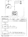
- Figure 17 illustrates the navigation flow of an external charger for recharging the INS
- Figure 18 illustrates the navigation flow of an external charger for recharging the external power source
- Figure 19 illustrates screen shots of charge status of an external charger
- Figure 20 illustrates status messages displayed during charging of the INS
- Figure 21 illustrates external power source charge status screens
- Figure 22 illustrates status messages displayed during recharging of the external power source
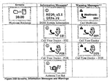
- FIGS 23A and 23B illustrate screens, information messages and warnings.
- external programming unit 2 is attachable via cord 4 to an external telemetry coil 6.
- External programming unit 2 can program operations of implantable medical device 16 ( Figure 2 ) in a conventional manner using external telemetry coil 6.
- External antenna 52 is attachable via cord 56 to external charging device 48 to inductively transfer power to implantable medical device 16 when external antenna 52 is placed in proximity of a secondary coil 24 associated with implantable medical device 16.
- External charging device 48 receives AC power from cord 8 through transformer 10.
- External antenna 52 can be held in position on patient 18 with belt 12.
- FIG. 2 illustrates an embodiment of implantable medical device 16 situated under cutaneous boundary 38.
- Charging regulation and therapy control is conventional.
- Implantable medical device 16 also has internal telemetry coil 44 configured in conventional manner to communicate through external telemetry coil 46 to an external programming device 2, charging unit 50 or other device in a conventional manner in order to both program and control implantable medical device and to externally obtain information from implantable medical device 16 once implantable medical device has been implanted.
- Internal telemetry coil 44 rectangular in shape with dimensions of 1.85 inches (4.7 centimeters) by 1.89 inches (4.8 centimeters) constructed from 150 turns of 43 AWG wire, is sized to be larger than the diameter of secondary charging coil 34.
- Secondary coil 34 is constructed with 182 turns of 30 AWG wire with an inside diameter of 0.72 inches (1.83 centimeters) and an outside diameter of 1.43 inches (3.63 centimeters) with a height of 0.075 inches (0.19 centimeters).
- Magnetic shield 36 is positioned between secondary charging coil 34 and housing 32 and sized to cover the footprint of secondary charging coil 34.
- Internal telemetry coil 44 having a larger diameter than secondary coil 34, is not completely covered by magnetic shield 36 allowing implantable medical device 16 to communicate with the external programming device with internal telemetry coil 44 in spite of the presence of magnetic shield 36.
- Rechargeable power source 24 can be charged while implantable medical device 16 is in place in a patient through the use of external charging device 48.
- external charging device 48 consists of charging unit 50 and external antenna 52.
- Charging unit 50 contains the electronics necessary to drive primary coil 54 with an oscillating current in order to induce current in secondary coil 34 when primary coil 54 is placed in the proximity of secondary coil 34.
- Charging unit 50 is operatively coupled to primary coil by cable 56.
- charging unit 50 and antenna 52 may be combined into a single unit.
- Antenna 52 also contains external telemetry coil 46 which may be operatively coupled to charging unit 50 if it is desired to communicate to or from implantable medical device 16 with external charging device 48.
- antenna 52 may contain external telemetry coil 46 which can be operatively coupled to external programming device 2, either individually or together with external charging unit 48.
- the user interface of external programming unit 2 is illustrated by reference to Figure 3 through Figure 16 .
- the following terms are used throughout the description of the user interface of external programming unit 2.
- DTC refers to desktop charger which is used to denote the AC power supply (transformer 10) and power cord (cord 8).
- the DTC is "docked” when external charger 48 is connected to an source of AC power.
- the DTC is "undocked” when external charger 48 is disconnected from a source of AC power.
- Name Label Function Power button - Turn display on and off - Turn backlight on when held down Therapy On - Turn therapy on - Turn display on if pressed when programmer is powered down Therapy Off - Turn therapy off - Turn display on if pressed when programmer is powered down.
- Increase - Change values Decrease - Change values Sync - Interrogate the implanted device; activate a group - Turn display on if pressed when programmer is powered down. Scroll Up/Down ⁇ ⁇ - Select displayed items Scroll Left/Right ⁇ - Access available choices for a selected item
- the LCD is backlit and consists of 96 (Horizontal) x 58 (Vertical) dots with asymmetrical dots 0.35 (H) x 0.4 (V).
- the active area on the LCD is 33.3 mm (H) x 23.2 mm (V).
- Four colors of display available are named below (from lightest to darkest):
- Therapy status screen display layout is divided vertically into three lines of information: status line, groups line and parameters line as shown in Figure 5 .
- software will display the Therapy Status Screen of the active set with the following highlighting priority: parameters line if displayed; groups line if displayed; and status line.
- Scroll up and scroll down keys will be used to access the status line, groups line and parameters line on the display. A box highlights user selection. Scroll left and right will be used to cycle through available choices for a selected line.
- Software will display a "real-time" INS charge level on the status line. The charge level will be updated and displayed whenever a parameter adjustment is made. Software will display programmer battery status on the status line.
- Software will display labels for all groups the user can activate, including those containing no adjustable parameters. Refer to Figure 7 for Group Selections. All unnecessary text will be removed from the display: e.g., if there is only 1 group, software will not display the groups line. Software will not display parameters that the user cannot adjust: i.e., the clinician programmer disallows access or upper and lower limits are the same. The user will access all available groups by scrolling through a linear list: A, B, C, ..., Z. When the user scrolls to a different group, software will display the first adjustable parameter in the group. The user will scroll left/right through available groups to access an inactive group.
- Software will display all adjustable parameters for inactive groups. The user will scroll down to highlight parameters and scroll left or right to view them. If a user presses Therapy Off or Therapy On when the screen displays an inactive group, software will turn the INS off, and display the Therapy Status Screen with the active group highlighted. A check in its check box will be used to indicate an active group (check_on); a check box without a check will be used to indicate inactive groups (check_off). The user will press the Sync key to activate a group at the displayed parameter value(s).
- the neurostimulator does not have to be on to activate a new group.
- the user can activate a group when therapy is off.
- the user can activate a new group when the groups line is highlighted or when the parameters line is highlighted.
- the check box will be updated whenever a new group is activated.
- Software will display labels for all parameters the user can adjust as shown in Figure 8 , Parameter Selections.
- Software will display the first adjustable parameter of the active group when a Sync has been performed for an initial interrogation. The user will access all adjustable parameters by scrolling through a linear list. The order of scrolling through adjustable parameters in a group is Amp1, Amp2, Amp3, Amp4, PW1, PW2, PW3, PW4, Rate, Amp1, ... Refer to Figure 8 , Parameter Selections.
- Increase/decrease keys will be inactive until a session has been initiated - i.e., the INS has been interrogated.
- software will send a change to the neurostimulator every 1 ⁇ 2 second.
- software will display the updated parameter value.
- Therapy control events are described in screens, information messages and warnings that are displayed on the programmer as shown in Figures 9A , 9B and 9C . Operational requirements are described in tables that specify conditions for entry and expected changes in control.
- the i symbol will be displayed on all information messages as shown in Figure 9 B.
- the user can clear all messages by pressing the 4-way button (Scroll up/down, Scroll left/right), Therapy Off to turn stimulation off or the Power button to turn the display off. If the system times out, the display will turn off (Power Down Screen).
- the 4-way button Scroll up/down, Scroll left/right
- Therapy Off to turn stimulation off
- the Power button to turn the display off. If the system times out, the display will turn off (Power Down Screen).
- Access to menu selections is from the status line on the Therapy Screen as shown in Figure 10 .
- the display is divided vertically into two lines of information: menu option line and value line. Scroll up and down keys will be used to access the menu option line and the value line on the display. A box highlights user selection. Scroll right and left and increase/decrease keys will be used to change values for Audio, Contrast, Time/Number Format and the Information options. In addition, Increase/decrease keys will be used to change values.
- Table 11 Menu Selections Software will display screens for the menu options in Table 11 Menu Selections.
- Table 111 Menu Selections and Navigation Flow Menu Item References Audio Figure 11 Table 12-1, 3, 9 Contrast Figure 12 , Table 12-1, 3, 4, 6, 7, 9 INS/ENS Time Figure 13 , Table 12-1, 2,4,7, 8, 9 Time/Number Format Figure 14 , Table 12-1, 3, 9 1 Patient Programmer Information Figure 15 , Table 12-1, 2, 9, 10 INS/ENS Information Figure 16 , Table 12-1, 2, 9, 10 Telemetry N Information Figure 16A , Table 12-1, 2, 9, 10
- the user interface of the external charger is described below.
- a description of the user interface for an external recharger for an implantable medical device is described.
- the appearance of the screens and how users interact with these screens are defined.
- DTC Desktop Charger ENS External Neurostimulator INS Implanted Neurostimulator INSR Another name for the RX1 Patient Recharger.
- Acronym stands for Implanted Neurostimulator Recharger LCD Liquid Crystal Display
- Figure 17 illustrates a process for charging rechargeable power source 24 in implantable medical device 16 by using external charging device 48.
- a patient may use belt 12 to attach external antenna 52 to the patient's body at approximately the location of implanted medical device 16. It is desirable that primary coil 54 of external antenna 52 be aligned as closely as possible with secondary coil 34 of implantable medical device 16. Techniques for attaching external antenna 52 to the patient's body and positioning primary coil 54 in close proximity to secondary coil 34 can be found in co-pending United States Patent Application Serial No. 10/837,506, filed April 30, 2004 .
- the patient may then press (step 110) the "Start Charge” button 90 ( Figure 1 ) on charging unit 50.
- Charging unit 50 determines (step 112) if telemetry with implantable medical device 16 is successful. If telemetry is unsuccessful (step 114), an error message is generated such as a telemetry timeout (Reposition Antenna - Press Start Charge), system error (Antenna Too Hot) or external charging device 48 error due to INSR battery low or INSR battery depleted and external charging device displays the appropriate message. If telemetry is successful, then charging unit 50 waits (step 116) and the appropriate charge status may be indicated (step 118) in the display of charging unit 50.
- charging unit 50 returns through step 118.
- the surface temperature of antenna 52 is monitored as well as the charging current and battery voltage levels. An error message is generated and charging is suspended if measurements are not within limits.
- charging unit 50 indicates in the display that charging is complete and the user may press the "Stop Charge” button 92 on charging unit 50 to terminate the charging process.
- the "Stop Charge” button 92 may be pressed at any time during the charging process in order to terminate the charging process, i.e., the user need not wait until the complete charging has been indicated.
- Charging unit 50 may be operated to charge rechargeable power 24 in implantable medical device 16 by the use of only two buttons, namely the "Start Charge” button 90 and the “Stop Charge” button 92. These are the only two buttons which need be used. While a preferred embodiment of charging unit 50 does contain a third button, namely "Silence” button 94, this third button is not necessary. "Silence” button 94 is used only to disable, or to re-enable, audio output of charging unit 50. Since audio feedback is not required for the charging process, this button may be used or not at the convenience of the user.
- charging unit 50 may itself be powered by a rechargeable power source, such as a battery. Since the charging process could take several hours, it would be desirable.
- FIG 18 illustrates the process used to charge the external charging unit 48.
- the external charging unit 48 is connected (step 124) to a suitable power source, such as a readily available AC power outlet.
- a check is made (step 126) to determine whether a "recharge event", i.e., an alert or alarm condition, has occurred and, if so, issue the appropriate message (step 128). If a "recharge event" has not occurred, the process updates and displays (step 130) the charge status of external charging device 48. If recharge of external charging is not complete (step 132), the process again updates and displays the charging status in step 130.
- charging unit 50 displays a message indicative of a complete charging process.
- the LCD is backlit and consists of 96 (Horizontal) x 58 (Vertical) dots with asymmetrical dots 0.35 (H) x 0.4 (V).
- the active area on the LCD is 23.2 mm (V) x 33.3 mm (H).
- the keypad has the following buttons. Name Label Function Start Charge - Start charge - Turn display on if pressed when recharger is powered down Stop Charge - Stop charge Audio - Toggle audio on/off - Turn display on if pressed when recharger is powered down Therapy On - Turn therapy on - Turn display on if pressed when recharger is powered down Therapy Off - Turn therapy off - Turn display on if pressed when recharger is powered down
- Table 12 Icons for Status Line Name File Icon Size Coordinates INSR Wait Signal msg_insr_wait_signal 14w x 16h R3 C5 Therapy On status_stim_on 16w x 16h R1 C6 Therapy Off status_stim_off 16w x 16h R1 C6 Audio On status_beep_on 17w x 14h R3 C27 Audio Off status_beep_off 17w x 14h R3 C27 INSR Batt1 status_hhp_battery_100 21w x 15h R2 C49 INSR Batt2 status_hhp_battery_75 21w x 15h R2 C49 INSR Batt3 status_hhp_battery_50 2.1w x 15h R2 C49 INSR Batt4 status_hhp_battery 25 21w x 15h R2 C49 INSR Batt5 status_hhp_battery_0 21w x 15h R2 C
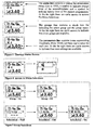
- the INS charge status screen display is divided vertically into three lines of information: status line, recharge progress line and recharge efficiency line. Refer to Figure 19 and Figure 20 .
- the INS battery status display has 5 settings: 0%, 25%, 50%, 75% and 100%.
- software will display the appropriate quartiles in solid fill and the next higher quartile in a flashing on/off manner every second. The exception is 100%. Even if the INS battery voltage indicates 100%, software will flash the last quartile until the recharge session is complete.
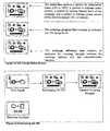
- the INSR charge status screen display is divided vertically into two lines of information: status line and recharge progress line. Refer to Figure 21 , INSR Charge Status Screen, and Figure 22 , Recharging the INSR.
- the INSR battery status has 5 settings: 0%, 25%, 50%, 75% and 100%.
- software will display the appropriate quartiles in solid fill and the next higher quartile in a flashing on/off manner every second. The exception is 100%. Even if the INSR battery voltage indicates 100%, software will flash the last quartile until the recharge session is complete.
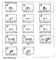
- Recharging events are described in screens, information messages and warnings that are displayed on the recharger as shown in Figure 23A and Figure 23 B.
- Operational requirements are described in tables that specify conditions for entry and expected changes in control. Refer to the operational requirements for each screen in this section.
- the i symbol will be displayed on all information messages. With the exception of INSR System Information screen, the user can exit the messages by pressing Audio or wait for the system to timeout. Therapy On and Off will always be active when the messages are displayed. When the user presses Therapy On or Off, software will turn stimulation on/off and clear the information message.
- the exclamation mark symbol will be displayed on all warnings. All warnings will remain on the display until the user takes appropriate action.
- Warning User Control / System Event Next Screen Recharge Stimulator - Start Charge and antenna temperature OK: Wait Screen (Table 17-1) - Start Charge and antenna too hot: Antenna Too Hot Message (Table 17-30) - System timeout: Power Down Recharge INSR - Attach DTC: INSR Charge Status Screen with Power Source Symbol - System timeout: Power Down Reposition Antenna - Press Start Charge - Start Charge and antenna temperature OK: Wait Screen (Table 17-1) - Start Charge and antenna too hot: Antenna Too Hot Message (Table 17-30) - System timeout: Power Down Reposition Antenna - Press Therapy Off - Therapy Off and telemetry success: Start Screen - Docked or Start Screen - Not Docked with Therapy Off icon on status line (Table 17-22) - Therapy Off and telemetry event: refer to Table 18 - System timeout: Power Down Reposition Antenna - Press Therapy On - Therapy On and telemetry success: Start Screen - Docked or Start Screen - Not Docked
- the primary purpose of external programming unit 2 is to manipulate therapeutic programs such as starting therapy and stopping therapy.
- the primary purpose of charging unit 50 is to charge or recharge rechargeable power source 24. However, patients may want to control their therapy while charging unit 50 is charging the rechargeable power source 24 of implantable medical device 16.
- charging unit 50 is also equipped with controls to start and stop therapy as well as controls to start and stop charging.
- External programming unit 2 and charging unit 50 both have similar "Therapy On” controls as illustrated in Table 1 and Table 11, respectively. Similarly, both external programming unit 2 and charging unit 50 also have similar "Therapy Off” controls as illustrated in Table 1 and Table 11, respectively.
- both external programming unit 2 and charging unit 50 also have similar or identical icons to display the same or similar messages to the user.
- Battery charging level icons “INSR Batt 1", “INSR Batt 2", “INSR Batt 3", “INSR Batt 4" and “INSR Batt 5" icons are similar or identical between external programming unit 2 and charging unit 50 as illustrated in Table 1 and Table 11, respectively.
- charging unit 50 receives information via telemetry from implantable medical device 16 during the charging process.
- External antenna 52 contains both primary coil 54 and external telemetry coil 46 and implantable medical device 16 contains both secondary coil 34 and internal telemetry coil 44.
- primary coil 54 can be inductively coupled to secondary coil 34 to facilitate the charging process.
- external telemetry coil 46 can be coupled with internal telemetry coil 44 to communicate information across cutaneous boundary 38 during the charging process.
- magnetic shield 36 prevents electromagnetic radiation stimulating secondary coil 34 from reaching the interior of housing 32 of implantable medical device.
- external telemetry coil 46 and internal telemetry coil 44 are sized to be larger than magnetic shield 36 allowing electromagnetic communication between external telemetry coil 46 and internal telemetry coil 44.
- a check is made to determine if telemetry is occurring between charging unit 50 and implantable medical device 16. Further, the status of charging rechargeable power source 24 is communicated from implantable medical device 16 and displayed by charging unit 50 (step 118).
- the charging status displayed by charging unit 50 can be the actual known charging status of rechargeable power source 24 as communicated from implantable medical device 16 to charging unit 50. This prevents essentially guessing the internal charging status of rechargeable power source 24 by some external means such as simply by the passage of time. Rather, the actual charging status of rechargeable power source 24, e.g., the battery voltage, can be measured and transmitted to charging unit 50 for display to the user.
- inductive charging and telemetry operations are time division multiplexed during the charging operation. That is, a portion of the time during which charging occurs is dedicated to telemetry. During this dedicated telemetry time, the inductive charging by primary coil 54 to secondary coil 34 is momentarily stopped and telemetry allowed to occur. As soon as telemetry has occurred and the required information has been communicated, inductive coupling can be resumed. Typically, only a relatively small portion of the time period during charging is required to be devoted to telemetry. Inductive charging can be stopped only for a short time, e.g., a few seconds, to allow for telemetry and then inductive charging can be resumed. Although the time division multiplexing occurs over the entire charging period, only a small portion of the charging time is lost to telemetry. Time division multiplexing of inductive coupling charging and telemetry prevents the possibility of inductive charging from interfering with telemetry signals.
Landscapes
- Health & Medical Sciences (AREA)
- Engineering & Computer Science (AREA)
- Biomedical Technology (AREA)
- Nuclear Medicine, Radiotherapy & Molecular Imaging (AREA)
- Radiology & Medical Imaging (AREA)
- Life Sciences & Earth Sciences (AREA)
- Animal Behavior & Ethology (AREA)
- General Health & Medical Sciences (AREA)
- Public Health (AREA)
- Veterinary Medicine (AREA)
- Electrotherapy Devices (AREA)
Claims (12)
- System einer implantierbaren medizinischen Vorrichtung, das enthält:eine implantierbare medizinische Vorrichtung (16) zum Bereitstellen einer therapeutischen Ausgabe für einen Patienten, wobei die implantierbare medizinische Vorrichtung (16) mit einer äußeren Patientensteuereinheit (2) kommunizieren kann, was dem Patienten erlaubt, die therapeutische Ausgabe der implantierbaren medizinischen Vorrichtung (16) zu steuern;eine äußere Patientensteuereinheit (2), die beschaffen ist, um über Telemetrie mit der implantierbaren medizinischen Vorrichtung (16) betriebsfähig gekoppelt zu sein, was dem Patienten erlaubt, die therapeutische Ausgabe der implantierbaren medizinischen Vorrichtung zu steuern, wobei die äußere Patientensteuereinheit (2) ein erstes Gehäuse und eine erste Benutzerschnittstelle besitzt, die durch den Patienten betreibbar ist und die Patienten-Steuerungen und Anzeige-Piktogramme, die den zustand des Betriebs der Patientensteuereinheit (2) anzeigen, besitzt; undeine äußere Energieübertragungseinheit (48), die ein zweites Gehäuse besitzt und beschaffen ist, um Energie transkutan zu der implantierbaren medizinischen Vorrichtung (16) zum Bereitstellen der therapeutischen Ausgabe für einen Patienten zu übertragen,dadurch gekennzeichnet, dass die äußere Energieübertragungseinheit umfasst:eine zweite Benutzerschnittstelle, die durch den Patienten betreibbar ist und die Patienten-Steuerungen und Anzeige-Piktogramme, die den Zustand des Betriebs der Energieübertragungseinheit (48) anzeigen, besitzt;wobei wenigstens einige der Patienten-Steuerungen und Anzeige-Piktogramme der Energieübertragungseinheit (48) mit wenigstens einigen der Patienten-Steuerungen und Anzeige-Piktogramme der Patientensteuereinheit (2) gemeinsam sind.
- System nach Anspruch 1, das weniger als drei betriebsfähige Steuerungen umfasst, um die Energieübertragung von der äußeren Energieübertragungseinheit (48) zu der implantierbaren medizinischen Vorrichtung (16) zu steuern.
- System nach Anspruch 1, wobei die implantierbare medizinische Vorrichtung (16) induktiv gekoppelte Energie mit einer Sekundärspule (34) empfangen kann und unter Verwendung einer inneren Telemetriespule (44) transkutan gesteuert werden kann; wobei das System ferner umfasst:eine äußere Antenne (52), die eine Primärspule (54) besitzt, die beschaffen ist, um Energie zu einer Sekundärspule (34) der implantierbaren medizinischen Vorrichtung (16) induktiv zu übertragen, wobei die äußere Antenne (52) in der Nähe der Sekundärspule (34) außen angeordnet ist; und wobeidie äußere Energieübertragungseinheit (48) beschaffen ist, um durch ein Kabel an die äußere Antenne (52) betriebsfähig gekoppelt zu sein und die Primärspule (54) anzutreiben, um induktiv Energie zu der implantierbaren medizinischen Vorrichtung (16) zu übertragen;die Energieübertragungseinheit (48) eine äußere Telemetriespule (46) besitzt, was es der Energieübertragungseinheit (48) erlaubt, durch die innere Telemetriespule (44) mit der implantierbaren medizinischen Vorrichtung (16) zu kommunizieren, um die therapeutische Ausgabe der implantierbaren medizinischen Vorrichtung (16) wenigstens teilweise zu steuern.
- System nach Anspruch 1, wobei das wenigstens eine der Anzeige-Piktogramme ein Piktogramm umfasst, das einen Zustand des Ladens einer Energiespeichervorrichtung in der implantierbaren medizinischen Vorrichtung (16) repräsentiert.
- System nach einem vorhergehenden Anspruch, wobei wenigstens eine der Patientensteuerungen eine Steuerung zum Einstellen der therapeutischen Ausgabe der implantierbaren medizinischen Vorrichtung (16) umfasst.
- System nach einem der Ansprüche 1 bis 4, wobei die äußere Energieübertragungseinheit (48) Energie an die implantierbare medizinische Vorrichtung (16) induktiv koppelt.
- System nach einem der Ansprüche 1 bis 4, wobei die implantierbare medizinische Vorrichtung (16) eine wiederaufladbare Energiespeichervorrichtung besitzt und wobei die Energieübertragungseinheit (48) die wiederaufladbare Energiespeichervorrichtung lädt.
- System nach Anspruch 1, wobei die Energieübertragungseinheit (48) mit zwei betriebsfähigen Steuerungen betreibbar ist, um die Energieübertragung von der äußeren Energieübertragungseinheit (48) zu der implantierbaren medizinischen Vorrichtung (16) zu steuern.
- System nach Anspruch 8, wobei die zwei betriebsfähigen Steuerungen eine Startsteuerung und eine Stoppsteuerung umfassen.
- System nach einem der Ansprüche 8 oder 9, wobei die Energieübertragungseinheit (48) ferner betriebsfähige Steuerungen umfasst, um die therapeutische Ausgabe der implantierbaren medizinischen Vorrichtung (16) zu starten und zu stoppen.
- System nach einem der Ansprüche 8 oder 9, wobei die äußere Energieübertragungseinheit (48) die Energie induktiv an die implantierbare medizinische Vorrichtung (16) koppelt.
- System nach einem der Ansprüche 8 oder 9, wobei die implantierbare medizinische Vorrichtung (16) eine wiederaufladbare Energiespeichervorrichtung besitzt und wobei die Energieübertragungseinheit (48) die wiederaufladbare Energiespeichervorrichtung lädt.
Applications Claiming Priority (3)
| Application Number | Priority Date | Filing Date | Title |
|---|---|---|---|
| US50819803P | 2003-10-02 | 2003-10-02 | |
| US51373203P | 2003-10-23 | 2003-10-23 | |
| PCT/US2004/032533 WO2005032658A1 (en) | 2003-10-02 | 2004-10-04 | User interface for external charger for implantable medical device |
Publications (2)
| Publication Number | Publication Date |
|---|---|
| EP1673143A1 EP1673143A1 (de) | 2006-06-28 |
| EP1673143B1 true EP1673143B1 (de) | 2012-08-22 |
Family
ID=34426043
Family Applications (1)
| Application Number | Title | Priority Date | Filing Date |
|---|---|---|---|
| EP04794037A Expired - Lifetime EP1673143B1 (de) | 2003-10-02 | 2004-10-04 | Benutzeroberfläche für externes ladegerät eines implantierbaren medizinischen gerätes |
Country Status (3)
| Country | Link |
|---|---|
| US (1) | US8346361B2 (de) |
| EP (1) | EP1673143B1 (de) |
| WO (1) | WO2005032658A1 (de) |
Families Citing this family (82)
| Publication number | Priority date | Publication date | Assignee | Title |
|---|---|---|---|---|
| US8396565B2 (en) | 2003-09-15 | 2013-03-12 | Medtronic, Inc. | Automatic therapy adjustments |
| US9259584B2 (en) * | 2003-10-02 | 2016-02-16 | Medtronic, Inc. | External unit for implantable medical device coupled by cord |
| US7437194B2 (en) * | 2003-10-31 | 2008-10-14 | Medtronic, Inc. | Stimulating the prostate gland |
| US7720546B2 (en) * | 2004-09-30 | 2010-05-18 | Codman Neuro Sciences Sárl | Dual power supply switching circuitry for use in a closed system |
| US7780613B2 (en) * | 2005-06-30 | 2010-08-24 | Depuy Products, Inc. | Apparatus, system, and method for transcutaneously transferring energy |
| US20070005141A1 (en) * | 2005-06-30 | 2007-01-04 | Jason Sherman | Apparatus, system, and method for transcutaneously transferring energy |
| US7551960B2 (en) * | 2005-09-08 | 2009-06-23 | Medtronic, Inc. | External presentation of electrical stimulation parameters |
| US7640059B2 (en) * | 2005-09-08 | 2009-12-29 | Medtronic, Inc. | External presentation of electrical stimulation parameters |
| US8495593B2 (en) * | 2005-09-09 | 2013-07-23 | International Business Machines Corporation | Method and system for state machine translation |
| US7957809B2 (en) | 2005-12-02 | 2011-06-07 | Medtronic, Inc. | Closed-loop therapy adjustment |
| US8075627B2 (en) * | 2006-04-07 | 2011-12-13 | Depuy Products, Inc. | System and method for transmitting orthopaedic implant data |
| US8015024B2 (en) | 2006-04-07 | 2011-09-06 | Depuy Products, Inc. | System and method for managing patient-related data |
| US7738965B2 (en) | 2006-04-28 | 2010-06-15 | Medtronic, Inc. | Holster for charging pectorally implanted medical devices |
| US20090187426A1 (en) * | 2006-05-31 | 2009-07-23 | Kerstna Juergen | Implantable medical device system and method for adapting functions of the clinician's workstation thereof |
| US7388288B2 (en) * | 2006-07-17 | 2008-06-17 | University Of Utah Research Foundation | Flip chip metallization method and devices |
| US9002445B2 (en) | 2006-07-28 | 2015-04-07 | Boston Scientific Neuromodulation Corporation | Charger with orthogonal PCB for implantable medical device |
| US8632464B2 (en) | 2006-09-11 | 2014-01-21 | DePuy Synthes Products, LLC | System and method for monitoring orthopaedic implant data |
| DE102007022286B4 (de) * | 2007-05-12 | 2009-01-15 | Dräger Medical AG & Co. KG | Medizinisches System mit galvanischer Trennung |
| US8901878B2 (en) * | 2007-06-05 | 2014-12-02 | Impulse Dynamics Nv | Transcutaneous charging device |
| US8080064B2 (en) | 2007-06-29 | 2011-12-20 | Depuy Products, Inc. | Tibial tray assembly having a wireless communication device |
| US8498716B2 (en) | 2007-11-05 | 2013-07-30 | Boston Scientific Neuromodulation Corporation | External controller for an implantable medical device system with coupleable external charging coil assembly |
| US20090251101A1 (en) * | 2008-04-02 | 2009-10-08 | Medtronic, Inc. | Holster for charging pectorally-implanted medical devices |
| US8708934B2 (en) | 2008-07-11 | 2014-04-29 | Medtronic, Inc. | Reorientation of patient posture states for posture-responsive therapy |
| US8200340B2 (en) | 2008-07-11 | 2012-06-12 | Medtronic, Inc. | Guided programming for posture-state responsive therapy |
| US8231556B2 (en) | 2008-07-11 | 2012-07-31 | Medtronic, Inc. | Obtaining baseline patient information |
| US9050471B2 (en) * | 2008-07-11 | 2015-06-09 | Medtronic, Inc. | Posture state display on medical device user interface |
| US8401666B2 (en) | 2008-07-11 | 2013-03-19 | Medtronic, Inc. | Modification profiles for posture-responsive therapy |
| US9545518B2 (en) | 2008-07-11 | 2017-01-17 | Medtronic, Inc. | Posture state classification for a medical device |
| US8515550B2 (en) | 2008-07-11 | 2013-08-20 | Medtronic, Inc. | Assignment of therapy parameter to multiple posture states |
| US8644945B2 (en) | 2008-07-11 | 2014-02-04 | Medtronic, Inc. | Patient interaction with posture-responsive therapy |
| US8504150B2 (en) | 2008-07-11 | 2013-08-06 | Medtronic, Inc. | Associating therapy adjustments with posture states using a stability timer |
| US8280517B2 (en) | 2008-09-19 | 2012-10-02 | Medtronic, Inc. | Automatic validation techniques for validating operation of medical devices |
| US8780047B2 (en) * | 2008-10-01 | 2014-07-15 | Wisconsin Alumni Research Foundation | Keyboard system and method for providing improved access to an electronic device |
| US8335569B2 (en) | 2009-02-10 | 2012-12-18 | Boston Scientific Neuromodulation Corporation | External device for communicating with an implantable medical device having data telemetry and charging integrated in a single housing |
| US9026223B2 (en) | 2009-04-30 | 2015-05-05 | Medtronic, Inc. | Therapy system including multiple posture sensors |
| US9327070B2 (en) | 2009-04-30 | 2016-05-03 | Medtronic, Inc. | Medical device therapy based on posture and timing |
| US8175720B2 (en) | 2009-04-30 | 2012-05-08 | Medtronic, Inc. | Posture-responsive therapy control based on patient input |
| US8214042B2 (en) | 2009-05-26 | 2012-07-03 | Boston Scientific Neuromodulation Corporation | Techniques for controlling charging of batteries in an external charger and an implantable medical device |
| US8827986B2 (en) | 2009-10-19 | 2014-09-09 | Pharmaco-Kinesis Corporation | Remotely activated piezoelectric pump for delivery of biological agents to the intervertebral disc and spine |
| EP2521981B1 (de) * | 2010-01-08 | 2021-08-18 | Medtronic, Inc. | Darstellung von informationen im zusammenhang mit anhand eines medizinischen gerätes verabreichten therapie |
| US8579834B2 (en) | 2010-01-08 | 2013-11-12 | Medtronic, Inc. | Display of detected patient posture state |
| US9357949B2 (en) | 2010-01-08 | 2016-06-07 | Medtronic, Inc. | User interface that displays medical therapy and posture data |
| US9956418B2 (en) | 2010-01-08 | 2018-05-01 | Medtronic, Inc. | Graphical manipulation of posture zones for posture-responsive therapy |
| US8758274B2 (en) | 2010-01-08 | 2014-06-24 | Medtronic, Inc. | Automated adjustment of posture state definitions for a medical device |
| US8352039B2 (en) * | 2010-01-08 | 2013-01-08 | Medtronic, Inc. | Programming therapy delivered by implantable medical device |
| US8594806B2 (en) | 2010-04-30 | 2013-11-26 | Cyberonics, Inc. | Recharging and communication lead for an implantable device |
| US9566441B2 (en) | 2010-04-30 | 2017-02-14 | Medtronic, Inc. | Detecting posture sensor signal shift or drift in medical devices |
| US8265556B2 (en) * | 2010-10-25 | 2012-09-11 | Waveworks, Inc. | Integrated mobile phone and medical implant monitoring system and method for using the same |
| US9002469B2 (en) | 2010-12-20 | 2015-04-07 | Abiomed, Inc. | Transcutaneous energy transfer system with multiple secondary coils |
| EP4112115B1 (de) | 2010-12-20 | 2026-02-11 | Abiomed, Inc. | Verfahren und system zum genauen verfolgen der verfügbaren last in einem transkutanen energieübertragungssystem |
| WO2012087819A2 (en) | 2010-12-20 | 2012-06-28 | Abiomed, Inc. | Transcutaneous energy transfer system with vibration inducing warning circuitry |
| US8712541B2 (en) | 2011-01-28 | 2014-04-29 | Medtronic, Inc. | Far field telemetry operations between an external device and an implantable medical device during recharge of the implantable medical device via a proximity coupling |
| EP4119184B1 (de) | 2011-04-14 | 2025-09-03 | Abiomed, Inc. | Transkutane energieübertragungsspule mit integrierter funkfrequenzantenne |
| US20130197607A1 (en) * | 2011-06-28 | 2013-08-01 | Greatbatch Ltd. | Dual patient controllers |
| US8954148B2 (en) | 2011-06-28 | 2015-02-10 | Greatbatch, Ltd. | Key fob controller for an implantable neurostimulator |
| US20130006330A1 (en) * | 2011-06-28 | 2013-01-03 | Greatbatch, Ltd. | Dual patient controllers |
| US9002468B2 (en) | 2011-12-16 | 2015-04-07 | Abiomed, Inc. | Automatic power regulation for transcutaneous energy transfer charging system |
| EP2794003B1 (de) | 2011-12-21 | 2018-01-24 | Boston Scientific Neuromodulation Corporation | System für eine implantierbare medizinische vorrichtung mit an zubehöraufladespulen koppelbarer externer ladevorrichtung |
| US8612015B2 (en) | 2012-03-20 | 2013-12-17 | James Dan Knifong, SR. | Molding device to precisely hold a recharge antenna |
| US9907959B2 (en) | 2012-04-12 | 2018-03-06 | Medtronic, Inc. | Velocity detection for posture-responsive therapy |
| US9737719B2 (en) | 2012-04-26 | 2017-08-22 | Medtronic, Inc. | Adjustment of therapy based on acceleration |
| US8886333B2 (en) | 2012-07-19 | 2014-11-11 | Boston Scientific Neuromodulation Corporation | Self-affixing external charging system for an implantable medical device |
| CA2879955C (en) | 2012-07-26 | 2021-08-10 | Adi Mashiach | Implant sleep apnea treatment device including an antenna |
| US9343923B2 (en) | 2012-08-23 | 2016-05-17 | Cyberonics, Inc. | Implantable medical device with backscatter signal based communication |
| US9935498B2 (en) | 2012-09-25 | 2018-04-03 | Cyberonics, Inc. | Communication efficiency with an implantable medical device using a circulator and a backscatter signal |
| US9537344B2 (en) * | 2013-02-21 | 2017-01-03 | Cyberonics, Inc. | Phase change material as a dynamic heat sink for trancutaneous energy transmission systems |
| US8805537B1 (en) | 2013-03-13 | 2014-08-12 | Medtronic, Inc. | Hybrid packing for implantable device |
| US9929584B2 (en) | 2014-10-30 | 2018-03-27 | Boston Scientific Neuromodulation Corporation | External charging coil assembly for charging a medical device |
| US10105545B2 (en) | 2015-03-12 | 2018-10-23 | Boston Scientific Neuromodulation Corporation | Assembly with a coaxial audio connector for charging an implantable medical device |
| USD815108S1 (en) * | 2015-06-09 | 2018-04-10 | Trilux Medical Gmbh & Co. Kg | Display screen or portion thereof with graphical user interface |
| US11129996B2 (en) | 2016-06-15 | 2021-09-28 | Boston Scientific Neuromodulation Corporation | External charger for an implantable medical device for determining position and optimizing power transmission using resonant frequency as determined from at least one sense coil |
| US10342984B2 (en) | 2016-06-15 | 2019-07-09 | Boston Scientific Neuromodulation Corporation | Split coil for uniform magnetic field generation from an external charger for an implantable medical device |
| US11471692B2 (en) | 2016-06-15 | 2022-10-18 | Boston Scientific Neuromodulation Corporation | External charger for an implantable medical device for adjusting charging power based on determined position using at least one sense coil |
| US10603501B2 (en) | 2016-06-15 | 2020-03-31 | Boston Scientific Neuromodulation Corporation | External charger for an implantable medical device having at least one sense coil concentric with a charging coil for determining position |
| US10363426B2 (en) | 2016-06-15 | 2019-07-30 | Boston Scientific Neuromodulation Corporation | External charger for an implantable medical device for determining position using phase angle or a plurality of parameters as determined from at least one sense coil |
| US10226637B2 (en) | 2016-06-15 | 2019-03-12 | Boston Scientific Neuromodulation Corporation | External charger for an implantable medical device having alignment and centering capabilities |
| USD857032S1 (en) * | 2017-09-10 | 2019-08-20 | Apple Inc. | Electronic device with graphical user interface |
| US10967192B2 (en) * | 2017-12-29 | 2021-04-06 | Boston Scientific Neuromodulation Corporation | Systems and methods for charging a medical device implanted into a patient |
| US11944833B2 (en) | 2019-10-25 | 2024-04-02 | Medtronic, Inc. | User centered system for recharging implanted neurostimulator |
| CN116157058B (zh) | 2020-07-21 | 2025-08-12 | 德普伊新特斯产品公司 | 骨固定监测系统 |
| US12453859B2 (en) | 2021-02-24 | 2025-10-28 | Medtronic, Inc. | Posture state definition calibration |
| US12458292B2 (en) | 2021-07-16 | 2025-11-04 | DePuy Synthes Products, Inc. | Smart plate sensors |
Family Cites Families (56)
| Publication number | Priority date | Publication date | Assignee | Title |
|---|---|---|---|---|
| US3942535A (en) | 1973-09-27 | 1976-03-09 | G. D. Searle & Co. | Rechargeable tissue stimulating system |
| US4082097A (en) * | 1976-05-20 | 1978-04-04 | Pacesetter Systems Inc. | Multimode recharging system for living tissue stimulators |
| US4232679A (en) | 1977-01-26 | 1980-11-11 | Pacesetter Systems, Inc. | Programmable human tissue stimulator |
| DE4104359A1 (de) | 1991-02-13 | 1992-08-20 | Implex Gmbh | Ladesystem fuer implantierbare hoerhilfen und tinnitus-maskierer |
| US5459671A (en) * | 1993-02-19 | 1995-10-17 | Advanced Micro Devices, Inc. | Programmable battery controller |
| US5411537A (en) | 1993-10-29 | 1995-05-02 | Intermedics, Inc. | Rechargeable biomedical battery powered devices with recharging and control system therefor |
| US6249703B1 (en) | 1994-07-08 | 2001-06-19 | Medtronic, Inc. | Handheld patient programmer for implantable human tissue stimulator |
| US5591217A (en) | 1995-01-04 | 1997-01-07 | Plexus, Inc. | Implantable stimulator with replenishable, high value capacitive power source and method therefor |
| US5630836A (en) | 1995-01-19 | 1997-05-20 | Vascor, Inc. | Transcutaneous energy and information transmission apparatus |
| US5690693A (en) | 1995-06-07 | 1997-11-25 | Sulzer Intermedics Inc. | Transcutaneous energy transmission circuit for implantable medical device |
| US5702431A (en) | 1995-06-07 | 1997-12-30 | Sulzer Intermedics Inc. | Enhanced transcutaneous recharging system for battery powered implantable medical device |
| US5724985A (en) | 1995-08-02 | 1998-03-10 | Pacesetter, Inc. | User interface for an implantable medical device using an integrated digitizer display screen |
| US5713937A (en) | 1995-11-07 | 1998-02-03 | Pacesetter, Inc. | Pacemaker programmer menu with selectable real or simulated implant data graphics |
| US5728154A (en) | 1996-02-29 | 1998-03-17 | Minnesota Mining And Manfacturing Company | Communication method for implantable medical device |
| US5782805A (en) | 1996-04-10 | 1998-07-21 | Meinzer; Randolph | Medical infusion pump |
| US5764034A (en) * | 1996-04-10 | 1998-06-09 | Baxter International Inc. | Battery gauge for a battery operated infusion pump |
| US6108579A (en) | 1996-04-15 | 2000-08-22 | Pacesetter, Inc. | Battery monitoring apparatus and method for programmers of cardiac stimulating devices |
| US5891178A (en) | 1996-05-14 | 1999-04-06 | Pacesetter, Inc. | Programmer system and associated methods for rapidly evaluating and programming an implanted cardiac device |
| US5733313A (en) | 1996-08-01 | 1998-03-31 | Exonix Corporation | RF coupled, implantable medical device with rechargeable back-up power source |
| US5713939A (en) | 1996-09-16 | 1998-02-03 | Sulzer Intermedics Inc. | Data communication system for control of transcutaneous energy transmission to an implantable medical device |
| US5735887A (en) | 1996-12-10 | 1998-04-07 | Exonix Corporation | Closed-loop, RF-coupled implanted medical device |
| US6072299A (en) | 1998-01-26 | 2000-06-06 | Medtronic Physio-Control Manufacturing Corp. | Smart battery with maintenance and testing functions |
| US6057758A (en) * | 1998-05-20 | 2000-05-02 | Hewlett-Packard Company | Handheld clinical terminal |
| US6558320B1 (en) * | 2000-01-20 | 2003-05-06 | Medtronic Minimed, Inc. | Handheld personal data assistant (PDA) with a medical device and method of using the same |
| US6393325B1 (en) | 1999-01-07 | 2002-05-21 | Advanced Bionics Corporation | Directional programming for implantable electrode arrays |
| US6127799A (en) | 1999-05-14 | 2000-10-03 | Gte Internetworking Incorporated | Method and apparatus for wireless powering and recharging |
| US6516227B1 (en) | 1999-07-27 | 2003-02-04 | Advanced Bionics Corporation | Rechargeable spinal cord stimulator system |
| US7177690B2 (en) | 1999-07-27 | 2007-02-13 | Advanced Bionics Corporation | Implantable system having rechargeable battery indicator |
| US6553263B1 (en) * | 1999-07-30 | 2003-04-22 | Advanced Bionics Corporation | Implantable pulse generators using rechargeable zero-volt technology lithium-ion batteries |
| US6820019B1 (en) | 1999-07-31 | 2004-11-16 | Medtronic, Inc. | Device and method for determining and communicating the remaining life of a battery in an implantable neurological tissue stimulating device |
| US6381496B1 (en) | 1999-10-01 | 2002-04-30 | Advanced Bionics Corporation | Parameter context switching for an implanted device |
| AU1618401A (en) | 1999-12-06 | 2001-06-12 | Advanced Bionics Corporation | Implantable device programmer |
| US7050857B2 (en) | 1999-12-16 | 2006-05-23 | St. Jude Medical Ab | Programming system for medical devices |
| US6473638B2 (en) | 1999-12-24 | 2002-10-29 | Medtronic, Inc. | Medical device GUI for cardiac electrophysiology display and data communication |
| US6665565B1 (en) | 1999-12-24 | 2003-12-16 | Medtronic, Inc. | Method and a system for conducting failure mode recovery in an implanted medical device |
| US6813519B2 (en) * | 2000-01-21 | 2004-11-02 | Medtronic Minimed, Inc. | Ambulatory medical apparatus and method using a robust communication protocol |
| US6451055B1 (en) | 2000-04-25 | 2002-09-17 | The Penn State Research Foundation | Artificial heart data communication system |
| US6456883B1 (en) | 2000-04-26 | 2002-09-24 | Medtronic, Inc. | Apparatus and method for allowing immediate retrieval for information and identification from an implantable medical device having a depleted power source |
| US6574503B2 (en) | 2000-04-26 | 2003-06-03 | Medtronic, Inc. | GUI coding for identification of displayable data quality from medical devices |
| US7167756B1 (en) | 2000-04-28 | 2007-01-23 | Medtronic, Inc. | Battery recharge management for an implantable medical device |
| US6453198B1 (en) | 2000-04-28 | 2002-09-17 | Medtronic, Inc. | Power management for an implantable medical device |
| WO2002009808A1 (en) | 2000-07-26 | 2002-02-07 | Advanced Bionics Corporation | Rechargeable spinal cord stimulator system |
| ATE490801T1 (de) * | 2000-09-13 | 2010-12-15 | Mann Medical Res Organization | Gerät zur konditionierung von muskeln im schlaf |
| US6583796B2 (en) | 2000-12-14 | 2003-06-24 | Medtronic, Inc. | Method and apparatus for displaying information retrieved from an implanted medical device |
| US7463930B2 (en) | 2000-12-20 | 2008-12-09 | Medtronic, Inc. | Implantable medical device programmer module for use with existing clinical instrumentation |
| US6650941B2 (en) | 2000-12-22 | 2003-11-18 | Medtronic, Inc. | Implantable medical device programming wands having integral input device |
| US6678563B2 (en) | 2001-03-30 | 2004-01-13 | Neurocontrol Corporation | Systems and methods for performing prosthetic or therapeutic neuromuscular stimulation using a universal external controller having a graphical user interface |
| US6591135B2 (en) | 2001-04-16 | 2003-07-08 | Ge Medical Systems Information Technologies, Inc. | Portable patient monitor with defibrillator/pacemaker interface and battery power management |
| US6671552B2 (en) | 2001-10-02 | 2003-12-30 | Medtronic, Inc. | System and method for determining remaining battery life for an implantable medical device |
| US7187978B2 (en) | 2001-11-01 | 2007-03-06 | Medtronic, Inc. | Method and apparatus for programming an implantable medical device |
| US6842644B2 (en) | 2001-11-02 | 2005-01-11 | Cardiac Pacemakers, Inc. | User navigation and guidance during configuration and storage of parameters for medical device |
| US20030177031A1 (en) | 2002-03-15 | 2003-09-18 | Medtronic, Inc. | Data management of patient medical information for use with an implantable medical device |
| US7010355B2 (en) | 2002-03-15 | 2006-03-07 | Medtronic, Inc. | Method and apparatus for connecting various implantable medical treatment system component devices |
| AU2003279616A1 (en) | 2002-06-28 | 2004-01-19 | Advanced Bionics Corporation | Microstimulator having self-contained power source and bi-directional telemetry system |
| US7209790B2 (en) | 2002-09-30 | 2007-04-24 | Medtronic, Inc. | Multi-mode programmer for medical device communication |
| US7489970B2 (en) * | 2003-04-02 | 2009-02-10 | Medtronic, Inc. | Management of neurostimulation therapy using parameter sets |
-
2004
- 2004-10-04 US US10/958,191 patent/US8346361B2/en active Active
- 2004-10-04 EP EP04794037A patent/EP1673143B1/de not_active Expired - Lifetime
- 2004-10-04 WO PCT/US2004/032533 patent/WO2005032658A1/en not_active Ceased
Also Published As
| Publication number | Publication date |
|---|---|
| EP1673143A1 (de) | 2006-06-28 |
| US20050113887A1 (en) | 2005-05-26 |
| WO2005032658A1 (en) | 2005-04-14 |
| US8346361B2 (en) | 2013-01-01 |
Similar Documents
| Publication | Publication Date | Title |
|---|---|---|
| US8346361B2 (en) | User interface for external charger for implantable medical device | |
| US11439836B2 (en) | External energy transfer system for an implantable medical device and method therefor | |
| EP1904153B1 (de) | Ausrichtungshinweis für den transkutanen energietransfer | |
| US9173992B2 (en) | Secure pairing of electronic devices using dual means of communication | |
| US10322287B2 (en) | Systems and methods for patient control of stimulation systems | |
| JP4703083B2 (ja) | 医療システム | |
| US9844677B2 (en) | External controller/charger system for an implantable medical device capable of automatically providing data telemetry through a charging coil during a charging session | |
| US20090062778A1 (en) | Medical System Comprising Dual-Purpose Communication Means | |
| US20040049245A1 (en) | Autonomous patch for communication with an implantable device, and medical kit for using said patch | |
| US8568356B2 (en) | Ambulatory medical apparatus with hand held communication device | |
| US20060017576A1 (en) | Alert system and method for an implantable medical device | |
| US20010012955A1 (en) | Method and apparatus for communicating with an implantable medical device | |
| US20070250130A1 (en) | Remote Communication System with Availability Indicator for an Implantable Medical Device | |
| WO2003008014A2 (en) | Ambulatory medical apparatus with hand held communication device | |
| JP2017538466A (ja) | 外部バッテリによって給電される外部充電コイルを有する埋込可能な医療デバイスシステムのための外部コントローラ | |
| WO1996020754A1 (en) | Implantable stimulator with replenishable, high value capacitive power source and method therefor | |
| US20030117442A1 (en) | Dynamic indication for capacitor charging status |
Legal Events
| Date | Code | Title | Description |
|---|---|---|---|
| PUAI | Public reference made under article 153(3) epc to a published international application that has entered the european phase |
Free format text: ORIGINAL CODE: 0009012 |
|
| 17P | Request for examination filed |
Effective date: 20060426 |
|
| AK | Designated contracting states |
Kind code of ref document: A1 Designated state(s): AT BE BG CH CY CZ DE DK EE ES FI FR GB GR HU IE IT LI LU MC NL PL PT RO SE SI SK TR |
|
| DAX | Request for extension of the european patent (deleted) | ||
| 17Q | First examination report despatched |
Effective date: 20090212 |
|
| GRAP | Despatch of communication of intention to grant a patent |
Free format text: ORIGINAL CODE: EPIDOSNIGR1 |
|
| GRAS | Grant fee paid |
Free format text: ORIGINAL CODE: EPIDOSNIGR3 |
|
| GRAA | (expected) grant |
Free format text: ORIGINAL CODE: 0009210 |
|
| AK | Designated contracting states |
Kind code of ref document: B1 Designated state(s): AT BE BG CH CY CZ DE DK EE ES FI FR GB GR HU IE IT LI LU MC NL PL PT RO SE SI SK TR |
|
| REG | Reference to a national code |
Ref country code: GB Ref legal event code: FG4D |
|
| REG | Reference to a national code |
Ref country code: CH Ref legal event code: EP |
|
| REG | Reference to a national code |
Ref country code: IE Ref legal event code: FG4D |
|
| REG | Reference to a national code |
Ref country code: AT Ref legal event code: REF Ref document number: 571617 Country of ref document: AT Kind code of ref document: T Effective date: 20120915 |
|
| REG | Reference to a national code |
Ref country code: DE Ref legal event code: R096 Ref document number: 602004039058 Country of ref document: DE Effective date: 20121018 |
|
| REG | Reference to a national code |
Ref country code: NL Ref legal event code: VDEP Effective date: 20120822 |
|
| REG | Reference to a national code |
Ref country code: AT Ref legal event code: MK05 Ref document number: 571617 Country of ref document: AT Kind code of ref document: T Effective date: 20120822 |
|
| PG25 | Lapsed in a contracting state [announced via postgrant information from national office to epo] |
Ref country code: CY Free format text: LAPSE BECAUSE OF FAILURE TO SUBMIT A TRANSLATION OF THE DESCRIPTION OR TO PAY THE FEE WITHIN THE PRESCRIBED TIME-LIMIT Effective date: 20120822 Ref country code: AT Free format text: LAPSE BECAUSE OF FAILURE TO SUBMIT A TRANSLATION OF THE DESCRIPTION OR TO PAY THE FEE WITHIN THE PRESCRIBED TIME-LIMIT Effective date: 20120822 Ref country code: FI Free format text: LAPSE BECAUSE OF FAILURE TO SUBMIT A TRANSLATION OF THE DESCRIPTION OR TO PAY THE FEE WITHIN THE PRESCRIBED TIME-LIMIT Effective date: 20120822 |
|
| PG25 | Lapsed in a contracting state [announced via postgrant information from national office to epo] |
Ref country code: SE Free format text: LAPSE BECAUSE OF FAILURE TO SUBMIT A TRANSLATION OF THE DESCRIPTION OR TO PAY THE FEE WITHIN THE PRESCRIBED TIME-LIMIT Effective date: 20120822 Ref country code: GR Free format text: LAPSE BECAUSE OF FAILURE TO SUBMIT A TRANSLATION OF THE DESCRIPTION OR TO PAY THE FEE WITHIN THE PRESCRIBED TIME-LIMIT Effective date: 20121123 Ref country code: SI Free format text: LAPSE BECAUSE OF FAILURE TO SUBMIT A TRANSLATION OF THE DESCRIPTION OR TO PAY THE FEE WITHIN THE PRESCRIBED TIME-LIMIT Effective date: 20120822 Ref country code: BE Free format text: LAPSE BECAUSE OF FAILURE TO SUBMIT A TRANSLATION OF THE DESCRIPTION OR TO PAY THE FEE WITHIN THE PRESCRIBED TIME-LIMIT Effective date: 20120822 Ref country code: PT Free format text: LAPSE BECAUSE OF FAILURE TO SUBMIT A TRANSLATION OF THE DESCRIPTION OR TO PAY THE FEE WITHIN THE PRESCRIBED TIME-LIMIT Effective date: 20121224 |
|
| PG25 | Lapsed in a contracting state [announced via postgrant information from national office to epo] |
Ref country code: NL Free format text: LAPSE BECAUSE OF FAILURE TO SUBMIT A TRANSLATION OF THE DESCRIPTION OR TO PAY THE FEE WITHIN THE PRESCRIBED TIME-LIMIT Effective date: 20120822 |
|
| PG25 | Lapsed in a contracting state [announced via postgrant information from national office to epo] |
Ref country code: DK Free format text: LAPSE BECAUSE OF FAILURE TO SUBMIT A TRANSLATION OF THE DESCRIPTION OR TO PAY THE FEE WITHIN THE PRESCRIBED TIME-LIMIT Effective date: 20120822 Ref country code: RO Free format text: LAPSE BECAUSE OF FAILURE TO SUBMIT A TRANSLATION OF THE DESCRIPTION OR TO PAY THE FEE WITHIN THE PRESCRIBED TIME-LIMIT Effective date: 20120822 Ref country code: EE Free format text: LAPSE BECAUSE OF FAILURE TO SUBMIT A TRANSLATION OF THE DESCRIPTION OR TO PAY THE FEE WITHIN THE PRESCRIBED TIME-LIMIT Effective date: 20120822 Ref country code: ES Free format text: LAPSE BECAUSE OF FAILURE TO SUBMIT A TRANSLATION OF THE DESCRIPTION OR TO PAY THE FEE WITHIN THE PRESCRIBED TIME-LIMIT Effective date: 20121203 Ref country code: CZ Free format text: LAPSE BECAUSE OF FAILURE TO SUBMIT A TRANSLATION OF THE DESCRIPTION OR TO PAY THE FEE WITHIN THE PRESCRIBED TIME-LIMIT Effective date: 20120822 |
|
| PG25 | Lapsed in a contracting state [announced via postgrant information from national office to epo] |
Ref country code: PL Free format text: LAPSE BECAUSE OF FAILURE TO SUBMIT A TRANSLATION OF THE DESCRIPTION OR TO PAY THE FEE WITHIN THE PRESCRIBED TIME-LIMIT Effective date: 20120822 Ref country code: MC Free format text: LAPSE BECAUSE OF NON-PAYMENT OF DUE FEES Effective date: 20121031 Ref country code: IT Free format text: LAPSE BECAUSE OF FAILURE TO SUBMIT A TRANSLATION OF THE DESCRIPTION OR TO PAY THE FEE WITHIN THE PRESCRIBED TIME-LIMIT Effective date: 20120822 Ref country code: SK Free format text: LAPSE BECAUSE OF FAILURE TO SUBMIT A TRANSLATION OF THE DESCRIPTION OR TO PAY THE FEE WITHIN THE PRESCRIBED TIME-LIMIT Effective date: 20120822 |
|
| REG | Reference to a national code |
Ref country code: CH Ref legal event code: PL |
|
| PLBE | No opposition filed within time limit |
Free format text: ORIGINAL CODE: 0009261 |
|
| STAA | Information on the status of an ep patent application or granted ep patent |
Free format text: STATUS: NO OPPOSITION FILED WITHIN TIME LIMIT |
|
| REG | Reference to a national code |
Ref country code: IE Ref legal event code: MM4A |
|
| GBPC | Gb: european patent ceased through non-payment of renewal fee |
Effective date: 20121122 |
|
| REG | Reference to a national code |
Ref country code: FR Ref legal event code: ST Effective date: 20130628 |
|
| 26N | No opposition filed |
Effective date: 20130523 |
|
| PG25 | Lapsed in a contracting state [announced via postgrant information from national office to epo] |
Ref country code: BG Free format text: LAPSE BECAUSE OF FAILURE TO SUBMIT A TRANSLATION OF THE DESCRIPTION OR TO PAY THE FEE WITHIN THE PRESCRIBED TIME-LIMIT Effective date: 20121122 Ref country code: CH Free format text: LAPSE BECAUSE OF NON-PAYMENT OF DUE FEES Effective date: 20121031 Ref country code: IE Free format text: LAPSE BECAUSE OF NON-PAYMENT OF DUE FEES Effective date: 20121004 Ref country code: LI Free format text: LAPSE BECAUSE OF NON-PAYMENT OF DUE FEES Effective date: 20121031 |
|
| PG25 | Lapsed in a contracting state [announced via postgrant information from national office to epo] |
Ref country code: FR Free format text: LAPSE BECAUSE OF NON-PAYMENT OF DUE FEES Effective date: 20121031 |
|
| REG | Reference to a national code |
Ref country code: DE Ref legal event code: R097 Ref document number: 602004039058 Country of ref document: DE Effective date: 20130523 |
|
| PG25 | Lapsed in a contracting state [announced via postgrant information from national office to epo] |
Ref country code: GB Free format text: LAPSE BECAUSE OF NON-PAYMENT OF DUE FEES Effective date: 20121122 |
|
| PG25 | Lapsed in a contracting state [announced via postgrant information from national office to epo] |
Ref country code: TR Free format text: LAPSE BECAUSE OF FAILURE TO SUBMIT A TRANSLATION OF THE DESCRIPTION OR TO PAY THE FEE WITHIN THE PRESCRIBED TIME-LIMIT Effective date: 20120822 |
|
| PG25 | Lapsed in a contracting state [announced via postgrant information from national office to epo] |
Ref country code: LU Free format text: LAPSE BECAUSE OF NON-PAYMENT OF DUE FEES Effective date: 20121004 |
|
| PG25 | Lapsed in a contracting state [announced via postgrant information from national office to epo] |
Ref country code: HU Free format text: LAPSE BECAUSE OF FAILURE TO SUBMIT A TRANSLATION OF THE DESCRIPTION OR TO PAY THE FEE WITHIN THE PRESCRIBED TIME-LIMIT Effective date: 20041004 |
|
| PGFP | Annual fee paid to national office [announced via postgrant information from national office to epo] |
Ref country code: DE Payment date: 20190918 Year of fee payment: 16 |
|
| REG | Reference to a national code |
Ref country code: DE Ref legal event code: R119 Ref document number: 602004039058 Country of ref document: DE |
|
| PG25 | Lapsed in a contracting state [announced via postgrant information from national office to epo] |
Ref country code: DE Free format text: LAPSE BECAUSE OF NON-PAYMENT OF DUE FEES Effective date: 20210501 |