EP1673192B1 - Alesoir - Google Patents
Alesoir Download PDFInfo
- Publication number
- EP1673192B1 EP1673192B1 EP04789547A EP04789547A EP1673192B1 EP 1673192 B1 EP1673192 B1 EP 1673192B1 EP 04789547 A EP04789547 A EP 04789547A EP 04789547 A EP04789547 A EP 04789547A EP 1673192 B1 EP1673192 B1 EP 1673192B1
- Authority
- EP
- European Patent Office
- Prior art keywords
- guide
- stratified
- reamer
- diamond
- reamer according
- Prior art date
- Legal status (The legal status is an assumption and is not a legal conclusion. Google has not performed a legal analysis and makes no representation as to the accuracy of the status listed.)
- Expired - Lifetime
Links
Images
Classifications
-
- B—PERFORMING OPERATIONS; TRANSPORTING
- B23—MACHINE TOOLS; METAL-WORKING NOT OTHERWISE PROVIDED FOR
- B23D—PLANING; SLOTTING; SHEARING; BROACHING; SAWING; FILING; SCRAPING; LIKE OPERATIONS FOR WORKING METAL BY REMOVING MATERIAL, NOT OTHERWISE PROVIDED FOR
- B23D77/00—Reaming tools
- B23D77/02—Reamers with inserted cutting edges
-
- B—PERFORMING OPERATIONS; TRANSPORTING
- B23—MACHINE TOOLS; METAL-WORKING NOT OTHERWISE PROVIDED FOR
- B23D—PLANING; SLOTTING; SHEARING; BROACHING; SAWING; FILING; SCRAPING; LIKE OPERATIONS FOR WORKING METAL BY REMOVING MATERIAL, NOT OTHERWISE PROVIDED FOR
- B23D2277/00—Reaming tools
- B23D2277/06—Connections between component parts
- B23D2277/061—Brazed connections
-
- B—PERFORMING OPERATIONS; TRANSPORTING
- B23—MACHINE TOOLS; METAL-WORKING NOT OTHERWISE PROVIDED FOR
- B23D—PLANING; SLOTTING; SHEARING; BROACHING; SAWING; FILING; SCRAPING; LIKE OPERATIONS FOR WORKING METAL BY REMOVING MATERIAL, NOT OTHERWISE PROVIDED FOR
- B23D2277/00—Reaming tools
- B23D2277/06—Connections between component parts
- B23D2277/065—Glued connections
-
- B—PERFORMING OPERATIONS; TRANSPORTING
- B23—MACHINE TOOLS; METAL-WORKING NOT OTHERWISE PROVIDED FOR
- B23D—PLANING; SLOTTING; SHEARING; BROACHING; SAWING; FILING; SCRAPING; LIKE OPERATIONS FOR WORKING METAL BY REMOVING MATERIAL, NOT OTHERWISE PROVIDED FOR
- B23D2277/00—Reaming tools
- B23D2277/24—Materials of the tool or the intended workpiece, methods of applying these materials
- B23D2277/2435—Cubic boron nitride [CBN]
-
- B—PERFORMING OPERATIONS; TRANSPORTING
- B23—MACHINE TOOLS; METAL-WORKING NOT OTHERWISE PROVIDED FOR
- B23D—PLANING; SLOTTING; SHEARING; BROACHING; SAWING; FILING; SCRAPING; LIKE OPERATIONS FOR WORKING METAL BY REMOVING MATERIAL, NOT OTHERWISE PROVIDED FOR
- B23D2277/00—Reaming tools
- B23D2277/24—Materials of the tool or the intended workpiece, methods of applying these materials
- B23D2277/2442—Diamond
-
- B—PERFORMING OPERATIONS; TRANSPORTING
- B23—MACHINE TOOLS; METAL-WORKING NOT OTHERWISE PROVIDED FOR
- B23D—PLANING; SLOTTING; SHEARING; BROACHING; SAWING; FILING; SCRAPING; LIKE OPERATIONS FOR WORKING METAL BY REMOVING MATERIAL, NOT OTHERWISE PROVIDED FOR
- B23D2277/00—Reaming tools
- B23D2277/24—Materials of the tool or the intended workpiece, methods of applying these materials
- B23D2277/2464—Hard metal, i.e. cemented carbide
-
- B—PERFORMING OPERATIONS; TRANSPORTING
- B23—MACHINE TOOLS; METAL-WORKING NOT OTHERWISE PROVIDED FOR
- B23D—PLANING; SLOTTING; SHEARING; BROACHING; SAWING; FILING; SCRAPING; LIKE OPERATIONS FOR WORKING METAL BY REMOVING MATERIAL, NOT OTHERWISE PROVIDED FOR
- B23D2277/00—Reaming tools
- B23D2277/46—Guiding pads
-
- Y—GENERAL TAGGING OF NEW TECHNOLOGICAL DEVELOPMENTS; GENERAL TAGGING OF CROSS-SECTIONAL TECHNOLOGIES SPANNING OVER SEVERAL SECTIONS OF THE IPC; TECHNICAL SUBJECTS COVERED BY FORMER USPC CROSS-REFERENCE ART COLLECTIONS [XRACs] AND DIGESTS
- Y10—TECHNICAL SUBJECTS COVERED BY FORMER USPC
- Y10T—TECHNICAL SUBJECTS COVERED BY FORMER US CLASSIFICATION
- Y10T407/00—Cutters, for shaping
- Y10T407/19—Rotary cutting tool
- Y10T407/1906—Rotary cutting tool including holder [i.e., head] having seat for inserted tool
- Y10T407/1908—Face or end mill
- Y10T407/191—Plural simultaneously usable separable tools in common seat or common clamp actuator for plural simultaneously usable tools
Definitions
- the invention relates to a reamer according to the preamble of patent claim 1.
- Reamers of this type have become known from EP 0 558 811 B1, DE 43 29 553 C1 and DE 197 46 462 C1 and are used for the production of accurate fitting bores with a smoothed bore surface. They each have a base body, which carries at least one guide strip in addition to a cutting effective, end-mounted cutting element, which extends with its longitudinal axis parallel to a rotation axis of the base body.
- a guide rail supports in a drilling process, the base body in the borehole, and relieved in terms of force a cutting element which causes by rotation of the body and under feed movement relative to a workpiece a chip removal at this.
- rubbing with a guide bar effectively smooths the bore surface when creating a hole. Therefore, it can be said that a guide rail satisfies smoothing and guiding functions.
- An error-free fulfillment of the above-mentioned functions of a guide bar is also desirable in a continuous use of reamers, as is common, for example, in the automotive industry. So far, to be as long as possible under high loads.
- cooling lubricant by which the guide strips should be kept at the lowest possible temperature when using a reamer to avoid welding of removed chips or parts thereof on the guide rails.
- One problem is that cooling lubricants are difficult to introduce into an area between the guide surface of a guide rail and a workpiece; Often a cooling effect can not be achieved to the required extent.
- guide rails which are usually made of hard metal, additionally with a coating, for example of diamond (EP 0 558 811 B1).
- the type of coating depends on the material to be processed, which is why reamers with differently coated guide rails are used for processing various materials.
- reamers with carbide guide rails which are coated with cubic boron nitride, are used, whereas for a machining of aluminum materials rather diamond-coated guide rails should be suitable.
- reamers with coated guide rails have low thicknesses or thicknesses of only a few micrometers.
- a coating is therefore rapidly worn when using a reamer.
- the best smoothing and guiding functions of a guide rail and the associated high hole quality can no longer be guaranteed.
- strong tangential forces occur in the insert, which affect the coated one Attack guide strips and act substantially in the direction of the interface carbide / coating, which can cause the coating to flake off.
- the object of the invention is to provide a reamer of the type mentioned, which is suitable for processing various materials and has a long service life.
- the stated object solves a reamer according to claim 1.
- a reamer according to the invention is suitable for machining workpieces made of different materials. Due to a composite construction of a guide strip and a course according to the invention of laminates results in a planar guide surface, which is composed of different materials. Each of these materials is particularly suitable for processing a particular material and, accordingly, a variety of reamer can be used. Since the layered body extending from a contact surface to a guide surface or vice versa, also effective for smoothing a bore surface material areas are always present even with long-term use and any wear in the area of the guide surface. Thus, a smoothing function can be ensured for a long time.
- the laminated bodies extend substantially parallel to the axis of rotation of the main body.
- a sequence of Schichtkörpem of different materials over the entire length of a guide bar is given and bore surfaces are smooth over the entire length of the guide bar with high quality. Also, effective cooling and, if necessary, lubrication over the entire length of a guide rail can be achieved.
- a reamer according to the invention in which the laminated bodies extend substantially normal to the direction of rotation of the base body.
- a tangential frictional force engages perpendicularly to the layer body of the guide strip when the reamer is used.
- a mutual detachment of the same or flaking of individual laminates is not only completely avoidable, but rather the individual laminates are pressed together by a tangential force.
- the guide strip has laminates of hard metal and laminates of diamond or cubic boron nitride.
- both softer metals such as aluminum and harder metals such as hardened steel alloys can advantageously be processed with a reamer.
- a diamond layer body causes a smoothing of a bore and a Guiding the reamer, whereas a cemented carbide body supports the smoothing diamond layer.
- a coolant lubricant channel is formed on the free surface of the or the hard metal layer body. If harder materials such as steels are machined, then the situation is reversed: hard-metal layer bodies cause smoothing, and diamond-layer bodies take on a supporting function, or cooling lubricant channels are formed in the guide surface area of the same.
- a guide strip comprises hard metal laminates with a thickness of 1000 ⁇ m to 1500 ⁇ m. Thicknesses of at least 1000 .mu.m prove to be favorable in terms of smoothing when machining steel. Thicknesses greater than 1500 microns can result in faster wear of the guide bar when machining aluminum alloy workpieces or a shorter use of the reamer.
- At least one layered body consists of cemented carbide and is bonded to a layered body of diamond, because a direct connection of cemented carbide layered body and diamond laminar body has a favorable effect on the durability of the composite structure or the durability of the composite laminate body of the guide strip.
- the layered body of diamond is deposited on the diamond by deposition of diamond Laminated body made of carbide is created. In this way, a particularly high load-bearing, direct and cohesive connection of smoothing Schichtkörpem be achieved, whereby a provision of reamers with a particularly long period of use is possible.
- Such a variant of a reamer is easy to produce. It is only necessary to coat hard metal laminates with dimensions corresponding to a guide strip to be produced on both sides with diamond and thus to produce individual components. Subsequently, the coated individual components can be joined together in the areas of the free surfaces of the diamond coatings, wherein preferably a first solder composition is used.
- this has proven to be a solder mass containing as main constituents copper and silver and as further elements of titanium and / or yttrium.
- this ultimately also forms a composite body, which should preferably have a thickness of 10 microns to 25 microns.
- a cohesion of diamond layers or a bonding effect can be impaired by the solder mass.
- Larger thicknesses than 25 microns should be avoided because the metallic solder mass heats up at a Reibahlenverassemble and thus more cooling is required.
- larger thicknesses than 25 microns do not have a positive effect on a cohesion of diamond layers.
- An attachment of the guide bar on the base body is advantageously carried out by a second solder mass, which has a lower melting point than a first solder mass.
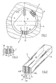
- FIG. 1 shows a schematic cross section through an end region of a reamer R according to the invention.
- a base body 1 with an axis A carries a cutting element 2, which is soldered or glued to the base body 1 or in any other way, for example by means of a clamping screw, may be attached.
- On the base body 1 two guide rails 3, 3 ' are further attached, which extend parallel to the axis A with respect to their longitudinal axes and are received by molded seats of the base body 1 positively.
- Guide rails 3, 3 ' can be adhesively bonded to the main body 1 with an adhesive or soldering compound.
- the guide strips 3, 3 ' are offset in the direction of rotation D of the cutting element 2 at angles of approximately 45 ° or 180 ° and each consist of laminas connected to one another Schichtkörpem 41, 42 which extend from a contact surface 31 to a guide surface 32 .
- Schichtkörpem 41, 42 which extend from a contact surface 31 to a guide surface 32 .
- a reamer R shown in Figure 1 with correspondingly extending laminates 41, 42 of the guide rails 3 is characterized by a particularly high resistance to acting tangential forces. While in coated guide rails, the coating in a rotational movement in the borehole B in direction D due to the forces acting parallel to a guide surface forces can be replaced due to a vertical position of the laminar body 41, 42, the guide rails 3, 3 ' inventive reamers now this Absorb forces easily.
- FIG. 2 shows an embodiment of the guide strip 3 of a reamer according to the invention.
- the guide strip 3 consists of a plurality of mutually parallel Schichtkörpem 43, 44, 45, which extend from a contact surface 31 to a guide surface 32 and extend over the entire length of the guide bar 3 .
- a guide strip 3 which is particularly easy to produce and shown in FIG. 2 may be such that a hard-metal layered body 43a forming a first side surface is connected over its entire surface to a layered body 44 made of diamond. This is followed by a sequence of Schichtkörpem 45, 44, 43b, 44, 45 or in the series of the corresponding materials solder mass - diamond - carbide - diamond - solder mass. Such a layered body series can be provided one or more times as needed. Finally, the second side surface is again followed by a layered body 44 made of diamond and a layered body 43a made of hard metal forming the second side area.
- a production of a guide strip shown in Figure 2 can be done in a simple manner by individual laminates 43a and 43b, each made of hard metal provided with dimensions that correspond to the guide bar to be created. Subsequently, layered body 43a on one side and layered body 43b coated on both sides with diamond. The components thus created are then bonded by bonding the laminates 44 of diamond with a solder mass and under Formation of Schichtkörpem 45 made of solder mass to a guide bar 3 assembled.
- the guide surface 32 comprises on the one hand in the region of the layer body 43 idealized planar areas 32a, through which surface regions 32a in use a smoothing of a surface and a bore guiding the reamer R is effected in a bore.
- vaulted areas 32b are present so that channels or hollows are formed in which cooling lubricants can be transported to smoothing-active flat areas 32a .
- a shaping of a guide surface shown in FIG. 3 could be observed during machining of aluminum workpieces. If a guide strip 3 in a state as shown in FIG. 3 is used to machine workpieces made of steel, then a substantially planar guide surface 32 arises, as it were, due to wear. As a result, by reversing the effect observed in aluminum machining, guide surface areas made of hard metal smooth the bore and guide the reamer, and coolant can be transported in the area of the diamond layer body.
Landscapes
- Engineering & Computer Science (AREA)
- Mechanical Engineering (AREA)
- Milling, Broaching, Filing, Reaming, And Others (AREA)
- Crystals, And After-Treatments Of Crystals (AREA)
- Drilling Tools (AREA)
Claims (13)
- Alésoir comprenant un corps de base (1) avec un élément de coupe (2) et au moins une barre conductrice (3, 3') sensiblement axialement orientée, qui comprend une surface d'appui (31) et une surface de guidage (32), ladite barre conductrice (3, 3') étant raccordée au corps de base (1) à la région de la surface d'appui (31), caractérisé en ce, que la barre conductrice (3, 3'), à partir de la surface de guidage (32) vers la surface d'appui (31), est formée par des stratifiés (41 à 45) en matériaux différents.
- Alésoir selon la revendication 1, caractérisé en ce, que les stratifiés (41 à 45) s'étendent sensiblement parallèlement à l'axe de rotation (A) du corps de base (1).
- Alésoir selon la revendication 1 ou 2, caractérisé en ce, que les stratifiés (41 à 45) s'étendent sensiblement normalement à la direction de rotation (A) du corps de base (1).
- Alésoir selon une quelconque des revendications 1 à 3, caractérisé en ce, que la barre conductrice (3, 3') comprend des stratifiés (43a; 43b) en métal dur et des stratifiés (44) en diamant ou en nitrure de bore cubique.
- Alésoir selon une quelconque des revendications 1 à 4, caractérisé en ce, que la barre conductrice (3, 3') comprend des stratifiés (43a; 43b) en métal dur d'une épaisseur de 1000 µm à 1500 µm.
- Alésoir selon une quelconque des revendications 1 à 5, caractérisé en ce, que la barre conductrice (3, 3') comprend des stratifiés (43a; 43b) en diamant ou en nitrure de bore cubique d'une épaisseur de 2 µm à 500 µm, particulièrement de 10 µm à 50 µm.
- Alésoir selon une quelconque des revendications 1 à 6, caractérisé en ce, qu'au moins un stratifié (43a, 43b) consiste de métal dur et est relié à un stratifié (44) en diamant.
- Alésoir selon la revendication 7, caractérisé en ce, que le stratifié (44) en diamant est produit par précipitation de diamant sur le stratifié (43a, 43b) en métal dur.
- Alésoir selon la revendication 7 ou 8, caractérisé en ce, que la barre conductrice (3, 3') comprend des stratifiés (44) en diamant, qui sont reliés avec une première masse à braser (45).
- Alésoir selon la revendication 9, caractérisé en ce, que la première masse à braser (45) comprend de cuivre et d'argent comme des constituants principaux, et de titane et/ou d'yttrium comme des autres éléments.
- Alésoir selon la revendication 9 ou 10, caractérisé en ce, que le/les stratifié(s) formé(s) par ladite première masse à braser (45) a (ont) une épaisseur de 10 µm à 25 µm.
- Alésoir selon une quelconque des revendications 9 à 11, caractérisé en ce, que la barre conductrice est raccordé au corps de base (1) par une seconde masse à braser, qui présente un point de fusion plus bas qu'une première masse à braser.
- Alésoir selon une quelconque des revendications 1 à 11, caractérisé en ce, que la barre conductrice (3, 3') est raccordé au corps de base (1) par une masse adhésive.
Applications Claiming Priority (2)
| Application Number | Priority Date | Filing Date | Title |
|---|---|---|---|
| AT0163303A AT500169A1 (de) | 2003-10-16 | 2003-10-16 | Reibahle |
| PCT/AT2004/000356 WO2005037476A1 (fr) | 2003-10-16 | 2004-10-18 | Alesoir |
Publications (2)
| Publication Number | Publication Date |
|---|---|
| EP1673192A1 EP1673192A1 (fr) | 2006-06-28 |
| EP1673192B1 true EP1673192B1 (fr) | 2007-03-14 |
Family
ID=34437843
Family Applications (1)
| Application Number | Title | Priority Date | Filing Date |
|---|---|---|---|
| EP04789547A Expired - Lifetime EP1673192B1 (fr) | 2003-10-16 | 2004-10-18 | Alesoir |
Country Status (6)
| Country | Link |
|---|---|
| US (1) | US20070147964A1 (fr) |
| EP (1) | EP1673192B1 (fr) |
| AT (2) | AT500169A1 (fr) |
| BR (1) | BRPI0415383A (fr) |
| DE (1) | DE502004003242D1 (fr) |
| WO (1) | WO2005037476A1 (fr) |
Families Citing this family (2)
| Publication number | Priority date | Publication date | Assignee | Title |
|---|---|---|---|---|
| EP2700463B1 (fr) * | 2012-08-22 | 2016-10-12 | Sandvik Intellectual Property AB | Procédé de fabrication d'une plaquette de support |
| EP2946862A1 (fr) * | 2014-05-21 | 2015-11-25 | Sandvik Intellectual Property AB | Coussinet de support et tête de coupe pour un outil de coupe rotatif |
Family Cites Families (17)
| Publication number | Priority date | Publication date | Assignee | Title |
|---|---|---|---|---|
| FR1317605A (fr) * | 1961-03-22 | 1963-05-08 | ||
| US3510990A (en) * | 1967-08-21 | 1970-05-12 | Engis Equipment Co | Tapered reamer |
| US3575247A (en) * | 1969-03-06 | 1971-04-20 | Shell Oil Co | Diamond bit unit |
| CA1154430A (fr) * | 1981-08-21 | 1983-09-27 | Paul Knutsen | Outil de foration a lame incorporee avec calibre cylindrique stabilisateur de l'effort de rognage |
| US5186268A (en) * | 1991-10-31 | 1993-02-16 | Camco Drilling Group Ltd. | Rotary drill bits |
| DE4202751A1 (de) * | 1992-01-31 | 1993-08-05 | Mapal Fab Praezision | Einmesser-reibahle |
| DE4329553C2 (de) * | 1993-09-02 | 1997-12-18 | Beck August Gmbh Co | Einmesser-Reibahle |
| IT1269964B (it) * | 1994-06-29 | 1997-04-16 | S E A Utensili Diamantati S P | Utensile porta-inserti diamantati per macchine automatiche e manuali tipo calibratrici, levigatrici e lucidatrici per l'industria lapidea, ceramica e piastrelle |
| DE4441648A1 (de) * | 1994-11-23 | 1996-05-30 | Beck August Gmbh Co | Verfahren zur Herstellung von Rohlingen für Führungsleisten für Einschneiden-Reibahlen und zum Finishen von Einschneiden-Reibahlen |
| US6089336A (en) * | 1995-10-10 | 2000-07-18 | Camco International (Uk) Limited | Rotary drill bits |
| DE19719893A1 (de) * | 1997-03-03 | 1998-11-19 | Maier Kg Andreas | Reib- und Senk-Schneidwerkzeug mit Kühlmittelzufuhr |
| US6206117B1 (en) * | 1997-04-02 | 2001-03-27 | Baker Hughes Incorporated | Drilling structure with non-axial gage |
| DE19746462C1 (de) * | 1997-10-21 | 1999-04-01 | Itw E V | Verfahren zur Herstellung einer Einschneiden-Reibahle und dergleichen |
| JP3847016B2 (ja) * | 1998-12-09 | 2006-11-15 | 富士精工株式会社 | 円形穴の仕上加工方法および一枚刃リーマ |
| US20030019106A1 (en) * | 2001-04-22 | 2003-01-30 | Diamicron, Inc. | Methods for making bearings, races and components thereof having diamond and other superhard surfaces |
| US7451836B2 (en) * | 2001-08-08 | 2008-11-18 | Smith International, Inc. | Advanced expandable reaming tool |
| JP4723302B2 (ja) * | 2005-07-25 | 2011-07-13 | ユニタック株式会社 | マシンリーマー |
-
2003
- 2003-10-16 AT AT0163303A patent/AT500169A1/de not_active Application Discontinuation
-
2004
- 2004-10-18 WO PCT/AT2004/000356 patent/WO2005037476A1/fr not_active Ceased
- 2004-10-18 US US10/575,873 patent/US20070147964A1/en not_active Abandoned
- 2004-10-18 BR BRPI0415383-9A patent/BRPI0415383A/pt not_active Application Discontinuation
- 2004-10-18 DE DE502004003242T patent/DE502004003242D1/de not_active Expired - Fee Related
- 2004-10-18 EP EP04789547A patent/EP1673192B1/fr not_active Expired - Lifetime
- 2004-10-18 AT AT04789547T patent/ATE356685T1/de not_active IP Right Cessation
Also Published As
| Publication number | Publication date |
|---|---|
| DE502004003242D1 (de) | 2007-04-26 |
| ATE356685T1 (de) | 2007-04-15 |
| US20070147964A1 (en) | 2007-06-28 |
| WO2005037476A1 (fr) | 2005-04-28 |
| EP1673192A1 (fr) | 2006-06-28 |
| AT500169A1 (de) | 2005-11-15 |
| BRPI0415383A (pt) | 2006-12-12 |
Similar Documents
| Publication | Publication Date | Title |
|---|---|---|
| DE69509600T2 (de) | Drehendes Schneidwerkzeug und dessen Herstellungsmethode | |
| DE102014207501B4 (de) | Rotationswerkzeug, insbesondere Bohrer sowie Verfahren zur Herstellung eines solchen Rotationswerkzeugs | |
| EP2542369B1 (fr) | Patin de guidage | |
| EP1931490B1 (fr) | Outil d'enlèvement de copeaux | |
| WO1989001384A1 (fr) | Agencement d'outillage pour soudage par ultrasons | |
| EP3385014B1 (fr) | Procédé de fabrication d'un outil de perçage par usinage par enlèvement de copeaux des pièces à usiner ainsi qu'outil de perçage | |
| EP2633931A2 (fr) | Couronne de perçage | |
| DE102016221363A1 (de) | Bohrwerkzeug und Verfahren zum Herstellen von Bohrungen | |
| EP1023962A1 (fr) | Outil de coupe avec moyen de contrôle de copeaux | |
| DE102015213755A1 (de) | Verfahren zur Herstellung eines Zerspanungswerkzeugs sowie Zerspanungswerkzeug | |
| EP1808250A1 (fr) | Lame de scie avec base et denture munie d'une pointe avec couche de protection contre l'usure | |
| DE19742765A1 (de) | Schneidplatte, insbesondere Wendeplatte, Verfahren zur Herstellung einer solchen Schneidplatte, mit solchen Schneidplatten ausgestattetes Werkzeug und Verfahren zum Zerspanen eines Werkstückes unter Verwendung einer solchen Schneidplatte oder unter Einsatz eines solchen Werkzeuges | |
| EP1610919B2 (fr) | Foret a une levre et son procede de production | |
| EP3681669B1 (fr) | Outil de rugosification et procédé de fabrication associé | |
| EP0715919B1 (fr) | Procédé et lame de scie pour le sciage des pièces en acier | |
| DE10354000A1 (de) | Gewindebohrer mit einem mit einer diamantartigen Kohlenstoffbeschichtung beschichteten Gewindeabschnitt | |
| EP1857238B1 (fr) | Dent de scie avec couche dure | |
| EP1912757A1 (fr) | Plaquette de coupe | |
| EP1673192B1 (fr) | Alesoir | |
| EP1888283B1 (fr) | Insert | |
| DE202016004094U1 (de) | Zerspanungswerkzeug | |
| EP3993938B1 (fr) | Outil d'usinage par enlèvement de copeaux à dents asymétriques munies de particules de coupe | |
| EP0924014A1 (fr) | Foret | |
| DE202005000994U1 (de) | Spanabhebendes Werkzeug | |
| EP3993939B1 (fr) | Outil de coupe en forme de bande avec particules tampons et procédé de frabrication |
Legal Events
| Date | Code | Title | Description |
|---|---|---|---|
| PUAI | Public reference made under article 153(3) epc to a published international application that has entered the european phase |
Free format text: ORIGINAL CODE: 0009012 |
|
| 17P | Request for examination filed |
Effective date: 20060303 |
|
| AK | Designated contracting states |
Kind code of ref document: A1 Designated state(s): AT BE BG CH CY CZ DE DK EE ES FI FR GB GR HU IE IT LI LU MC NL PL PT RO SE SI SK TR |
|
| GRAP | Despatch of communication of intention to grant a patent |
Free format text: ORIGINAL CODE: EPIDOSNIGR1 |
|
| GRAS | Grant fee paid |
Free format text: ORIGINAL CODE: EPIDOSNIGR3 |
|
| DAX | Request for extension of the european patent (deleted) | ||
| GRAA | (expected) grant |
Free format text: ORIGINAL CODE: 0009210 |
|
| AK | Designated contracting states |
Kind code of ref document: B1 Designated state(s): AT BE BG CH CY CZ DE DK EE ES FI FR GB GR HU IE IT LI LU MC NL PL PT RO SE SI SK TR |
|
| PG25 | Lapsed in a contracting state [announced via postgrant information from national office to epo] |
Ref country code: IE Free format text: LAPSE BECAUSE OF FAILURE TO SUBMIT A TRANSLATION OF THE DESCRIPTION OR TO PAY THE FEE WITHIN THE PRESCRIBED TIME-LIMIT Effective date: 20070314 Ref country code: FI Free format text: LAPSE BECAUSE OF FAILURE TO SUBMIT A TRANSLATION OF THE DESCRIPTION OR TO PAY THE FEE WITHIN THE PRESCRIBED TIME-LIMIT Effective date: 20070314 Ref country code: PL Free format text: LAPSE BECAUSE OF FAILURE TO SUBMIT A TRANSLATION OF THE DESCRIPTION OR TO PAY THE FEE WITHIN THE PRESCRIBED TIME-LIMIT Effective date: 20070314 Ref country code: NL Free format text: LAPSE BECAUSE OF FAILURE TO SUBMIT A TRANSLATION OF THE DESCRIPTION OR TO PAY THE FEE WITHIN THE PRESCRIBED TIME-LIMIT Effective date: 20070314 Ref country code: SI Free format text: LAPSE BECAUSE OF FAILURE TO SUBMIT A TRANSLATION OF THE DESCRIPTION OR TO PAY THE FEE WITHIN THE PRESCRIBED TIME-LIMIT Effective date: 20070314 |
|
| REG | Reference to a national code |
Ref country code: GB Ref legal event code: FG4D Free format text: NOT ENGLISH |
|
| REG | Reference to a national code |
Ref country code: CH Ref legal event code: EP |
|
| REF | Corresponds to: |
Ref document number: 502004003242 Country of ref document: DE Date of ref document: 20070426 Kind code of ref document: P |
|
| REG | Reference to a national code |
Ref country code: IE Ref legal event code: FG4D Free format text: LANGUAGE OF EP DOCUMENT: GERMAN |
|
| PG25 | Lapsed in a contracting state [announced via postgrant information from national office to epo] |
Ref country code: SE Free format text: LAPSE BECAUSE OF FAILURE TO SUBMIT A TRANSLATION OF THE DESCRIPTION OR TO PAY THE FEE WITHIN THE PRESCRIBED TIME-LIMIT Effective date: 20070614 |
|
| PG25 | Lapsed in a contracting state [announced via postgrant information from national office to epo] |
Ref country code: ES Free format text: LAPSE BECAUSE OF FAILURE TO SUBMIT A TRANSLATION OF THE DESCRIPTION OR TO PAY THE FEE WITHIN THE PRESCRIBED TIME-LIMIT Effective date: 20070625 |
|
| PG25 | Lapsed in a contracting state [announced via postgrant information from national office to epo] |
Ref country code: PT Free format text: LAPSE BECAUSE OF FAILURE TO SUBMIT A TRANSLATION OF THE DESCRIPTION OR TO PAY THE FEE WITHIN THE PRESCRIBED TIME-LIMIT Effective date: 20070814 |
|
| NLV1 | Nl: lapsed or annulled due to failure to fulfill the requirements of art. 29p and 29m of the patents act | ||
| GBV | Gb: ep patent (uk) treated as always having been void in accordance with gb section 77(7)/1977 [no translation filed] |
Effective date: 20070314 |
|
| REG | Reference to a national code |
Ref country code: IE Ref legal event code: FD4D |
|
| EN | Fr: translation not filed | ||
| EN | Fr: translation not filed | ||
| PG25 | Lapsed in a contracting state [announced via postgrant information from national office to epo] |
Ref country code: GB Free format text: LAPSE BECAUSE OF FAILURE TO SUBMIT A TRANSLATION OF THE DESCRIPTION OR TO PAY THE FEE WITHIN THE PRESCRIBED TIME-LIMIT Effective date: 20070314 Ref country code: SK Free format text: LAPSE BECAUSE OF FAILURE TO SUBMIT A TRANSLATION OF THE DESCRIPTION OR TO PAY THE FEE WITHIN THE PRESCRIBED TIME-LIMIT Effective date: 20070314 |
|
| PG25 | Lapsed in a contracting state [announced via postgrant information from national office to epo] |
Ref country code: CZ Free format text: LAPSE BECAUSE OF FAILURE TO SUBMIT A TRANSLATION OF THE DESCRIPTION OR TO PAY THE FEE WITHIN THE PRESCRIBED TIME-LIMIT Effective date: 20070314 Ref country code: RO Free format text: LAPSE BECAUSE OF FAILURE TO SUBMIT A TRANSLATION OF THE DESCRIPTION OR TO PAY THE FEE WITHIN THE PRESCRIBED TIME-LIMIT Effective date: 20070314 |
|
| PLBE | No opposition filed within time limit |
Free format text: ORIGINAL CODE: 0009261 |
|
| STAA | Information on the status of an ep patent application or granted ep patent |
Free format text: STATUS: NO OPPOSITION FILED WITHIN TIME LIMIT |
|
| PG25 | Lapsed in a contracting state [announced via postgrant information from national office to epo] |
Ref country code: DK Free format text: LAPSE BECAUSE OF FAILURE TO SUBMIT A TRANSLATION OF THE DESCRIPTION OR TO PAY THE FEE WITHIN THE PRESCRIBED TIME-LIMIT Effective date: 20070314 |
|
| 26N | No opposition filed |
Effective date: 20071217 |
|
| BERE | Be: lapsed |
Owner name: BOEHLERIT GMBH & CO.KG. Effective date: 20071031 |
|
| PG25 | Lapsed in a contracting state [announced via postgrant information from national office to epo] |
Ref country code: GR Free format text: LAPSE BECAUSE OF FAILURE TO SUBMIT A TRANSLATION OF THE DESCRIPTION OR TO PAY THE FEE WITHIN THE PRESCRIBED TIME-LIMIT Effective date: 20070615 Ref country code: FR Free format text: LAPSE BECAUSE OF FAILURE TO SUBMIT A TRANSLATION OF THE DESCRIPTION OR TO PAY THE FEE WITHIN THE PRESCRIBED TIME-LIMIT Effective date: 20071102 Ref country code: IT Free format text: LAPSE BECAUSE OF FAILURE TO SUBMIT A TRANSLATION OF THE DESCRIPTION OR TO PAY THE FEE WITHIN THE PRESCRIBED TIME-LIMIT Effective date: 20070314 |
|
| PG25 | Lapsed in a contracting state [announced via postgrant information from national office to epo] |
Ref country code: MC Free format text: LAPSE BECAUSE OF NON-PAYMENT OF DUE FEES Effective date: 20071031 |
|
| PG25 | Lapsed in a contracting state [announced via postgrant information from national office to epo] |
Ref country code: BE Free format text: LAPSE BECAUSE OF NON-PAYMENT OF DUE FEES Effective date: 20071031 |
|
| PG25 | Lapsed in a contracting state [announced via postgrant information from national office to epo] |
Ref country code: FR Free format text: LAPSE BECAUSE OF FAILURE TO SUBMIT A TRANSLATION OF THE DESCRIPTION OR TO PAY THE FEE WITHIN THE PRESCRIBED TIME-LIMIT Effective date: 20070314 |
|
| PG25 | Lapsed in a contracting state [announced via postgrant information from national office to epo] |
Ref country code: EE Free format text: LAPSE BECAUSE OF FAILURE TO SUBMIT A TRANSLATION OF THE DESCRIPTION OR TO PAY THE FEE WITHIN THE PRESCRIBED TIME-LIMIT Effective date: 20070314 |
|
| PGFP | Annual fee paid to national office [announced via postgrant information from national office to epo] |
Ref country code: DE Payment date: 20081022 Year of fee payment: 5 |
|
| PG25 | Lapsed in a contracting state [announced via postgrant information from national office to epo] |
Ref country code: AT Free format text: LAPSE BECAUSE OF NON-PAYMENT OF DUE FEES Effective date: 20071018 |
|
| REG | Reference to a national code |
Ref country code: CH Ref legal event code: PL |
|
| PG25 | Lapsed in a contracting state [announced via postgrant information from national office to epo] |
Ref country code: CY Free format text: LAPSE BECAUSE OF FAILURE TO SUBMIT A TRANSLATION OF THE DESCRIPTION OR TO PAY THE FEE WITHIN THE PRESCRIBED TIME-LIMIT Effective date: 20070314 |
|
| PG25 | Lapsed in a contracting state [announced via postgrant information from national office to epo] |
Ref country code: LU Free format text: LAPSE BECAUSE OF NON-PAYMENT OF DUE FEES Effective date: 20071018 Ref country code: BG Free format text: LAPSE BECAUSE OF FAILURE TO SUBMIT A TRANSLATION OF THE DESCRIPTION OR TO PAY THE FEE WITHIN THE PRESCRIBED TIME-LIMIT Effective date: 20070614 |
|
| PG25 | Lapsed in a contracting state [announced via postgrant information from national office to epo] |
Ref country code: HU Free format text: LAPSE BECAUSE OF FAILURE TO SUBMIT A TRANSLATION OF THE DESCRIPTION OR TO PAY THE FEE WITHIN THE PRESCRIBED TIME-LIMIT Effective date: 20070915 Ref country code: TR Free format text: LAPSE BECAUSE OF FAILURE TO SUBMIT A TRANSLATION OF THE DESCRIPTION OR TO PAY THE FEE WITHIN THE PRESCRIBED TIME-LIMIT Effective date: 20070314 |
|
| PG25 | Lapsed in a contracting state [announced via postgrant information from national office to epo] |
Ref country code: CH Free format text: LAPSE BECAUSE OF NON-PAYMENT OF DUE FEES Effective date: 20081031 Ref country code: LI Free format text: LAPSE BECAUSE OF NON-PAYMENT OF DUE FEES Effective date: 20081031 |
|
| PG25 | Lapsed in a contracting state [announced via postgrant information from national office to epo] |
Ref country code: DE Free format text: LAPSE BECAUSE OF NON-PAYMENT OF DUE FEES Effective date: 20100501 |