EP1673304B1 - Grue mobile - Google Patents
Grue mobile Download PDFInfo
- Publication number
- EP1673304B1 EP1673304B1 EP03818801A EP03818801A EP1673304B1 EP 1673304 B1 EP1673304 B1 EP 1673304B1 EP 03818801 A EP03818801 A EP 03818801A EP 03818801 A EP03818801 A EP 03818801A EP 1673304 B1 EP1673304 B1 EP 1673304B1
- Authority
- EP
- European Patent Office
- Prior art keywords
- ballast
- superlift
- base structure
- mobile crane
- backmast
- Prior art date
- Legal status (The legal status is an assumption and is not a legal conclusion. Google has not performed a legal analysis and makes no representation as to the accuracy of the status listed.)
- Expired - Lifetime
Links
Images


Classifications
-
- B—PERFORMING OPERATIONS; TRANSPORTING
- B66—HOISTING; LIFTING; HAULING
- B66C—CRANES; LOAD-ENGAGING ELEMENTS OR DEVICES FOR CRANES, CAPSTANS, WINCHES, OR TACKLES
- B66C23/00—Cranes comprising essentially a beam, boom, or triangular structure acting as a cantilever and mounted for translatory of swinging movements in vertical or horizontal planes or a combination of such movements, e.g. jib-cranes, derricks, tower cranes
- B66C23/18—Cranes comprising essentially a beam, boom, or triangular structure acting as a cantilever and mounted for translatory of swinging movements in vertical or horizontal planes or a combination of such movements, e.g. jib-cranes, derricks, tower cranes specially adapted for use in particular purposes
- B66C23/36—Cranes comprising essentially a beam, boom, or triangular structure acting as a cantilever and mounted for translatory of swinging movements in vertical or horizontal planes or a combination of such movements, e.g. jib-cranes, derricks, tower cranes specially adapted for use in particular purposes mounted on road or rail vehicles; Manually-movable jib-cranes for use in workshops; Floating cranes
-
- B—PERFORMING OPERATIONS; TRANSPORTING
- B66—HOISTING; LIFTING; HAULING
- B66C—CRANES; LOAD-ENGAGING ELEMENTS OR DEVICES FOR CRANES, CAPSTANS, WINCHES, OR TACKLES
- B66C23/00—Cranes comprising essentially a beam, boom, or triangular structure acting as a cantilever and mounted for translatory of swinging movements in vertical or horizontal planes or a combination of such movements, e.g. jib-cranes, derricks, tower cranes
- B66C23/62—Constructional features or details
- B66C23/72—Counterweights or supports for balancing lifting couples
- B66C23/74—Counterweights or supports for balancing lifting couples separate from jib
Definitions
- the present invention relates to a mobile crane, preferably a self-propelled mobile crane, of the type having a travelling base structure which allows for travel of said crane over a surface and furthermore having a revolving superstructure mounted on said base structure and rotatable about a vertical revolving axis with respect to the base structure.
- the present invention also relates to a method for operating such a mobile crane.
- the crane further has a boom and a backmast, said boom and backmast each being hinged about an associated horizontal pivot axis to said superstructure.
- a main load hoisting means is associated with said boom for hoisting the load.
- the crane also has a superstructure ballast and the superstructure is adapted for supporting said superstructure ballast thereon.
- the crane For performing so-called “superlifts” the crane has a superlift ballast.
- Associated connection means serves to connect said superlift ballast to said backmast while said superlift ballast is resting on said surface and/or suspended from said backmast above said surface at a large distance from the base structure.
- the crane can resist very large overturning moments created by the load.
- the superlift ballast can weigh hundred or even several hundred metric tons.
- the ballast is usually composed of a stack of heavy steel plates.
- Mobile cranes of this type are often employed for several lift jobs at a single construction site, e.g. of a chemical plant. This means that for each job the crane has to be moved, e.g. several tens or hundreds of meters, to a new location and prepared for the new job.
- a disadvantage of prior art mobile cranes of the type described above relates to the practice described above, wherein the crane is moved from one location to the next. With most prior art cranes it is necessary to provide additional cranes and transport vehicles in order to move the superlift ballast to the new location. This is time consuming and poses additional safety hazards to personnel.
- the Demag CC 8800 crane has a superlift ballast car (max 600 ton) attached to the base structure via a telescopic beam. This crane further has a superstructure ballast mounted on the rear end of the superstructure.
- a "central ballast" (max 100 ton) is provided on the chassis of the base structure. This is done by providing the front and rear beam of the base structure with a centrally arranged support platform on which metal ballast plates can be stacked.
- a further prior art mobile crane is disclosed in US 6 568 547 , wherein the crane is not provided with a superstructure ballast.
- This crane has a horizontal beam attached to the superstructure, which beam carries the superlift ballast.
- the present invention aims to provide an improved mobile crane, having provisions for handling the superlift ballast which allow for a more efficient use of the crane at affordable costs.
- the present invention provides a mobile crane according to the preamble of claim 1, which is characterized in that said travelling base structure is provided with superlift ballast support means which allow for supporting said superlift ballast on said base structure so that said superlift ballast is movable along with the mobile crane while being supported by said base structure.
- the present invention thus proposes to use the travelling base of the crane itself, which is preferably self-propelled, as means to support and transport the superlift ballast when moving the crane from one job site to the next. This can result in a crane of lower costs than the complex prior art designs and/or a crane which can be operated far more efficiently.
- the present invention also relates to a method for operating such a mobile crane.
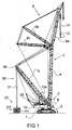
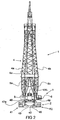
- the figures 1 and 2 show in different set-ups for different lift jobs crawler crane 1 designed for lifting loads of several hundred metric tons, in a preferred embodiment up to 1200 metric tons or even more.
- the crane 1 is a self-propelled crane and has a travelling base structure 2 which allows for travel of said crane over a surface.
- said surface will be the ground, possibly reinforced by a suitable foundation, but it is also envisaged that the crane is used on a large pontoon or the like.
- a revolving superstructure 3 is mounted on said base structure 2, so that the superstructure 3 can rotate about a vertical revolving axis with respect to the base structure 2.
- the crane 1 further has a boom 4 and a backmast 5.
- the boom is hinged to the superstructure 3 so that the boom 4 pivots about horizontal pivot axis 6.
- the backmast 5 is also hinged to the superstructure 3 about a horizontal pivot axis 7.
- both the boom 4 and the backmast 5 have a lattice structure, which is preferably modular to allow for easy transport of the entire crane from one construction site to the next.
- both the boom 4 has an A-frame design, with two elongated boom sections 4a, 4b separately connected to the superstructure and merging towards each other near the top of the boom 4.
- the backmast 5 has a inverted Y-frame design with two lower backmast sections 5a, 5b pivoted to the superstructure 3 and merging into a single section 5c.
- luffing fly jib arrangement 8 including jib 8a and stay beams 8b, 8c which are connected to the top of the boom 4.
- a main load hoisting means is associated with the boom 4 for hoisting a load.
- a hoisting cable 11 is shown, which is guided over cable pulleys 12 mounted on the top of the backmast 5, on the stay beams 8b, 8c and on the top of the jib 8a.
- a crane hook 13 is suspended from the hoisting cable 11.
- a main load-hoisting winch 13a is mounted on the revolving superstructure 3.
- a superstructure ballast 15 is provided, composed of a stack of steel ballast plates.
- the rear end of the superstructure 3 is adapted for supporting said superstructure ballast 15 thereon.
- the crane 1 further has a superlift ballast 20 and associated connection means 30 serving to connect said superlift ballast 20 to the backmast 5 while the superlift ballast 20 is resting on the surface (as in figure 1) and/or suspended from said backmast 5 above said surface.
- connection means 30 are formed here by a superlift ballast cable 31 guided over a cable pulley 32 in the top of the backmast 5 and connected to a superlift ballast winch 33 mounted on the superstructure 3.
- the travelling base structure 2 is provided with superlift ballast support means which allow for supporting said superlift ballast 20 on said base structure 2 so that said superlift ballast 20 is movable along with the crane 1 while being supported by said base structure 2.
- the travelling base structure 2 comprises a central chassis 40 (shown in detail in figure 5) and a first and second carriage assembly 41, 42 on opposite lateral sides of the chassis 40.
- the carriage assemblies are designed as crawler assemblies each having a track.
- Other designs are also envisaged such as wheeled carriage assemblies (for smaller cranes) or skid arrangements and the like.
- first and second crawler assemblies 41, 42 protrude forward and rearward with respect to the central chassis 40.
- the travelling base structure 2, in this example the chassis 40 thereof, is provided with a first and a second superlift ballast support means 50, 55 located on opposite sides thereof, in this example to the front and to the rear of the chassis 40.
- the superlift ballast 20 here comprises a first and a second superlift ballast part 20a, 20b, which are supportable on said first and second superlift ballast support means 50, 55 respectively.
- first and second superlift ballast support means 50, 55 are adapted such that said first superlift ballast part 20a is supported essentially in front of the chassis 40 between the forward protruding carriage assembly parts and the second super lift ballast part 20b is supported essentially to the rear of the chassis 40 between the rearward protruding carriage assembly parts.
- the superlift ballast parts 20a, 20b are supported such on said travelling base structure 2 that unhindered revolving motion of the superstructure 3 is possible when the ballast parts are supported on the chassis.
- the first and second super lift ballast parts 20a, 20b here each include two interconnectable ballast trays 16 and multiple ballast plates 17 stackable on said each of said ballast trays 16.
- Each tray 16 has a bottom 16a and sidewalls 16b.
- the sidewalls 16b have a connection member 16c at one edge allowing for a sort of tongue-and-groove connection to the associated tray 16 and also to a corresponding vertical connection member 43 on the chassis 40.
- the chassis 40 has two transverse beams 44, 45 extending between the crawler assemblies and two longitudinal beams 46, 47 interconnecting the transverse beams 44, 45.
- a slew ring 47a is mounted onto which a number of bogies 48 having rollers are supported. These bogies 48 support the superstructure 3 on the slew ring 47a in a rotatable manner (see e.g. fig. 2).
- hydraulic jacks 49 are visible on the chassis 40, near each of the carriage assemblies, which jacks serve to stabilise the crane 1 as it is stationary on the surface.
- the entire super ballast 20 is brought closer to the base structure 2 by lifting the ballast 20 from the surface and topping the backmast 5. Then said ballast 20 is lowered onto the ground and the ballast parts 20a, 20b are disconnected from each other. The ballast lifting cable 31 is then connected only to the ballast part 20a, which is then lifted.
- the ballast part 20a is bought between the forward part of the crawler assemblies and then lowered so that this ballast part 20a comes to rest on the associated support means 50 of the chassis 40 (see figures 3c and 4c). The ballast lifting cable is then disconnected from the ballast part 20a.
- the superstructure 3 is slewed back so that the cable can be attached to the other super lift ballast part 20b.
- This ballast part 20b is then lifted and by slewing the superstructure and topping the backmast 5, the ballast part 20b is brought between the rear end of the crawler assemblies.
- the ballast part 20b is then lowered onto the associated support means 55 of the chassis 40.
- ballast parts 20a, 20b on the structure 2 are also possible.
- the mobile crane 1 can be moved to another job location and the superlift ballast 20 is taken along with the (self-propelled) crane 1.
- the superlift ballast 20 could consist of one part only, which is then supported on a suitable location on the travelling base structure. It is however preferred to have multiple superlift ballast parts supported on opposite sides of the chassis.
Landscapes
- Engineering & Computer Science (AREA)
- Mechanical Engineering (AREA)
- Jib Cranes (AREA)
- Vehicle Body Suspensions (AREA)
- Control And Safety Of Cranes (AREA)
Claims (10)
- Grue mobile (1), de préférence grue mobile automotrice, comprenant :- une structure de base itinérante (2), qui permet de déplacer la grue sur une surface,- une superstructure rotative (3) montée sur la structure de base,- une flèche (4) et un mât arrière (5), la flèche et le mât arrière étant chacun articulé à la superstructure rotative (3) autour d'un axe formant pivot horizontal associé,- des moyens de levage de charge principaux (11, 13a) associés à la flèche pour lever une charge,- un lest de superstructure (15), la superstructure rotative (3) étant conçue pour supporter le lest de superstructure sur elle,- un lest de super-levage (20, 20a, 20b) et des moyens de raccordement associés (30) servant à raccorder le lest de super-levage au mât arrière (5), tandis que le lest de super-levage repose sur la surface et/ou est suspendu au mât arrière au-dessus de la surface,caractérisée en ce que
la structure de base itinérante (2) est pourvue de moyens de support de lest de super-levage (50, 55), qui permettent de supporter le lest de super-levage (20a, 20b) sur la structure de base de telle sorte que le lest de super-levage puisse être déplacé en même temps que la grue mobile tout en étant supporté par la structure de base (2). - Grue mobile selon la revendication 1, dans laquelle le lest de super-levage (20a, 20b) est supporté sur la structure de base mobile (2) de telle sorte que la superstructure (3) puisse tourner sans entrave.
- Grue mobile selon la revendication 1 ou 2, dans laquelle la structure de base itinérante (2) comprend un châssis central (40), ainsi qu'un premier et un deuxième ensembles porteurs (41, 42) sur chaque côté latéral du châssis.
- Grue mobile selon l'une quelconque des revendications 1 à 3, dans laquelle la structure de base itinérante (2) est pourvue de premiers et de deuxièmes moyens de support de lest de super-levage (50, 55) situés de chaque côté de la structure de base (2), et dans laquelle le lest de super-levage comprend au moins une première et une deuxième parties de lest de super-levage (20a, 20b), qui peuvent être supportées sur les premiers et deuxièmes moyens de support de lest de super-levage respectifs.
- Grue mobile selon les revendications 3 et 4, dans laquelle les premier et deuxième ensembles porteurs (41, 42) dépassent vers l'avant et vers l'arrière par rapport au châssis central (40), et dans laquelle les premiers et deuxièmes moyens de support de lest de super-levage (50, 55) sont conçus de façon que la première partie de lest de super-levage (20a) soit supportée essentiellement à l'avant du châssis, entre les parties des ensembles porteurs dépassant vers l'avant, et que la deuxième partie de lest de super-levage (20b) soit supportée essentiellement à l'avant du châssis, entre les parties des ensembles porteurs dépassant vers l'arrière.
- Grue mobile selon la revendication 4 ou 5, dans laquelle les première et deuxième parties de lest de super-levage (20a, 20b) comprennent chacune un plateau de lest (16) et plusieurs plaques de lest (17) pouvant être empilées sur le plateau de lest.
- Grue mobile selon la revendication 6, dans laquelle les plateaux de lest (16) sont pourvus de moyens de raccordement (16c) permettant le raccordement mutuel des plateaux, de telle sorte que les plateaux raccordés puissent être utilisés pendant le levage d'une charge par la grue mobile.
- Grue mobile selon l'une quelconque des revendications précédentes, dans laquelle des moyens de levage de lest de super-levage (31, 33) sont associés au mât arrière (5), de telle sorte que le lest de super-levage (20, 20a, 20b) puisse être suspendu au mât arrière, le mât arrière (5) pouvant être positionné de telle sorte que le lest de super-levage puisse être amené en support sur les moyens de support de lest de super-levage (50, 55) de la grue mobile.
- Grue mobile selon l'une quelconque des revendications 2 à 8, dans laquelle les ensembles porteurs sont des ensembles à chenilles (41, 42).
- Procédé d'actionnement d'une grue mobile selon une ou plusieurs des revendications précédentes, dans lequel le lest de super-levage (20a, 20b) est amené à reposer sur les moyens de support de lest de super-levage (50, 55) de la structure de base itinérante (2), de telle sorte que le lest de super-levage soit déplacé en même temps que la grue mobile tout en étant supporté par la structure de base.
Applications Claiming Priority (1)
| Application Number | Priority Date | Filing Date | Title |
|---|---|---|---|
| PCT/NL2003/000674 WO2005030632A1 (fr) | 2003-10-02 | 2003-10-02 | Grue mobile |
Publications (2)
| Publication Number | Publication Date |
|---|---|
| EP1673304A1 EP1673304A1 (fr) | 2006-06-28 |
| EP1673304B1 true EP1673304B1 (fr) | 2007-09-12 |
Family
ID=34386848
Family Applications (1)
| Application Number | Title | Priority Date | Filing Date |
|---|---|---|---|
| EP03818801A Expired - Lifetime EP1673304B1 (fr) | 2003-10-02 | 2003-10-02 | Grue mobile |
Country Status (6)
| Country | Link |
|---|---|
| EP (1) | EP1673304B1 (fr) |
| CN (1) | CN100436303C (fr) |
| AT (1) | ATE372951T1 (fr) |
| AU (1) | AU2003276776A1 (fr) |
| DE (1) | DE60316358T2 (fr) |
| WO (1) | WO2005030632A1 (fr) |
Families Citing this family (7)
| Publication number | Priority date | Publication date | Assignee | Title |
|---|---|---|---|---|
| DE102006015307A1 (de) * | 2005-11-17 | 2007-05-24 | Terex-Demag Gmbh & Co. Kg | Mobiler Großkran |
| DE102006060347B4 (de) * | 2006-12-20 | 2008-09-25 | Liebherr-Werk Ehingen Gmbh | Gitterstück für einen mobilen Großkran und Verfahren zu seinem Aufrichten |
| CN101049892B (zh) * | 2007-04-12 | 2012-05-23 | 山东富友有限公司 | 臂架类起重机平衡系统匹配方法及实现该方法的起重机 |
| DE102007056289B4 (de) * | 2007-10-29 | 2009-06-04 | Liebherr-Werk Ehingen Gmbh | Verfahren zum Aufrichten eines Kranauslegers |
| CN102735440B (zh) * | 2012-07-05 | 2014-12-24 | 中联重科股份有限公司 | 超起机构的试验装置 |
| NL2012074C2 (en) | 2014-01-10 | 2015-07-13 | Itrec Bv | Double jib slewing pedestal crane. |
| NL2017776B1 (en) * | 2016-11-11 | 2018-05-24 | Itrec Bv | Marine crane vessel and method of operation |
Family Cites Families (7)
| Publication number | Priority date | Publication date | Assignee | Title |
|---|---|---|---|---|
| JPS59207394A (ja) * | 1983-05-11 | 1984-11-24 | 株式会社神戸製鋼所 | 超大型クレ−ン |
| CN2030991U (zh) * | 1988-05-11 | 1989-01-18 | 河南省宝丰县石桥机械厂 | 农村建房用小型机(手)动提升装置 |
| DE29724688U1 (de) * | 1997-08-07 | 2003-02-06 | Demag Mobile Cranes GmbH & Co. KG, 80333 München | Gegenmassewagen eines Kranes |
| DE29816385U1 (de) * | 1998-09-11 | 1999-04-08 | Liebherr-Werk Ehingen Gmbh, 89584 Ehingen | Kran, vorzugsweise Derrickkran |
| DE19857779A1 (de) * | 1998-12-04 | 2000-06-15 | Mannesmann Ag | Kran, insbesondere Fahrzeugkran |
| JP3424616B2 (ja) * | 1999-09-09 | 2003-07-07 | コベルコ建機株式会社 | クローラ走行式の作業機械 |
| DE20014268U1 (de) * | 2000-08-18 | 2002-01-03 | Liebherr-Werk Ehingen Gmbh, 89584 Ehingen | Fahrbarer Kran |
-
2003
- 2003-10-02 WO PCT/NL2003/000674 patent/WO2005030632A1/fr not_active Ceased
- 2003-10-02 DE DE60316358T patent/DE60316358T2/de not_active Expired - Lifetime
- 2003-10-02 AU AU2003276776A patent/AU2003276776A1/en not_active Abandoned
- 2003-10-02 EP EP03818801A patent/EP1673304B1/fr not_active Expired - Lifetime
- 2003-10-02 CN CNB2003801107519A patent/CN100436303C/zh not_active Expired - Fee Related
- 2003-10-02 AT AT03818801T patent/ATE372951T1/de not_active IP Right Cessation
Also Published As
| Publication number | Publication date |
|---|---|
| AU2003276776A1 (en) | 2005-04-14 |
| EP1673304A1 (fr) | 2006-06-28 |
| CN100436303C (zh) | 2008-11-26 |
| WO2005030632A1 (fr) | 2005-04-07 |
| DE60316358T2 (de) | 2008-06-12 |
| CN1878721A (zh) | 2006-12-13 |
| DE60316358D1 (de) | 2007-10-25 |
| ATE372951T1 (de) | 2007-09-15 |
Similar Documents
| Publication | Publication Date | Title |
|---|---|---|
| US4394911A (en) | Heavy duty crane | |
| US4446976A (en) | Reversible outrigger crane support | |
| US8584801B2 (en) | Self-climbing hoist, deck and scaffold platform system | |
| US6516961B1 (en) | Ringlift crane | |
| US5615784A (en) | Crane counterweight installation and removal apparatus | |
| US10246310B2 (en) | Large mobile crane | |
| EP0856486B1 (fr) | Système de manipulation du contrepoids de grues tournantes | |
| JP6756518B2 (ja) | クレーンを操作する方法及びクレーン | |
| US4053060A (en) | Crane | |
| US4381060A (en) | Ring supported mobile tower crane | |
| US4483448A (en) | Heavy duty crane | |
| NL2024563B1 (en) | Crane, vessel comprising such a crane, and a method for up-ending a longitudinal structure | |
| EP4605334A1 (fr) | Grue ayant une flèche de grue pourvue d'un système de câble stabilisateur | |
| US4336889A (en) | Ring supported truck crane and method of setting up | |
| US5018630A (en) | High-capacity lift crane assembly | |
| GB2071052A (en) | Lift cranes | |
| US7213716B2 (en) | Crane | |
| EP1673304A1 (fr) | Grue mobile | |
| US7370767B2 (en) | Mobile crane | |
| US20020070186A1 (en) | Mobile crane | |
| CA1093505A (fr) | Grue-tour sur bague de pivotement | |
| EP4698478A1 (fr) | Grue ayant une flèche de grue avec un système de câbles stabilisateurs ayant une poutre transversale | |
| CN216625115U (zh) | 一种电缆随车运输与敷设一体化装置 | |
| CA1138824A (fr) | Grue mobile sur tournant | |
| EP4087809A1 (fr) | Système de grue de levage lourd mobile |
Legal Events
| Date | Code | Title | Description |
|---|---|---|---|
| PUAI | Public reference made under article 153(3) epc to a published international application that has entered the european phase |
Free format text: ORIGINAL CODE: 0009012 |
|
| 17P | Request for examination filed |
Effective date: 20060403 |
|
| AK | Designated contracting states |
Kind code of ref document: A1 Designated state(s): AT BE BG CH CY CZ DE DK EE ES FI FR GB GR HU IE IT LI LU MC NL PT RO SE SI SK TR |
|
| GRAP | Despatch of communication of intention to grant a patent |
Free format text: ORIGINAL CODE: EPIDOSNIGR1 |
|
| DAX | Request for extension of the european patent (deleted) | ||
| GRAS | Grant fee paid |
Free format text: ORIGINAL CODE: EPIDOSNIGR3 |
|
| GRAA | (expected) grant |
Free format text: ORIGINAL CODE: 0009210 |
|
| AK | Designated contracting states |
Kind code of ref document: B1 Designated state(s): AT BE BG CH CY CZ DE DK EE ES FI FR GB GR HU IE IT LI LU MC NL PT RO SE SI SK TR |
|
| REG | Reference to a national code |
Ref country code: GB Ref legal event code: FG4D |
|
| REG | Reference to a national code |
Ref country code: CH Ref legal event code: EP |
|
| REF | Corresponds to: |
Ref document number: 60316358 Country of ref document: DE Date of ref document: 20071025 Kind code of ref document: P |
|
| REG | Reference to a national code |
Ref country code: IE Ref legal event code: FG4D |
|
| PG25 | Lapsed in a contracting state [announced via postgrant information from national office to epo] |
Ref country code: FI Free format text: LAPSE BECAUSE OF FAILURE TO SUBMIT A TRANSLATION OF THE DESCRIPTION OR TO PAY THE FEE WITHIN THE PRESCRIBED TIME-LIMIT Effective date: 20070912 |
|
| PG25 | Lapsed in a contracting state [announced via postgrant information from national office to epo] |
Ref country code: LI Free format text: LAPSE BECAUSE OF FAILURE TO SUBMIT A TRANSLATION OF THE DESCRIPTION OR TO PAY THE FEE WITHIN THE PRESCRIBED TIME-LIMIT Effective date: 20070912 Ref country code: CH Free format text: LAPSE BECAUSE OF FAILURE TO SUBMIT A TRANSLATION OF THE DESCRIPTION OR TO PAY THE FEE WITHIN THE PRESCRIBED TIME-LIMIT Effective date: 20070912 Ref country code: AT Free format text: LAPSE BECAUSE OF FAILURE TO SUBMIT A TRANSLATION OF THE DESCRIPTION OR TO PAY THE FEE WITHIN THE PRESCRIBED TIME-LIMIT Effective date: 20070912 |
|
| PG25 | Lapsed in a contracting state [announced via postgrant information from national office to epo] |
Ref country code: BE Free format text: LAPSE BECAUSE OF FAILURE TO SUBMIT A TRANSLATION OF THE DESCRIPTION OR TO PAY THE FEE WITHIN THE PRESCRIBED TIME-LIMIT Effective date: 20070912 |
|
| REG | Reference to a national code |
Ref country code: CH Ref legal event code: PL |
|
| PG25 | Lapsed in a contracting state [announced via postgrant information from national office to epo] |
Ref country code: ES Free format text: LAPSE BECAUSE OF FAILURE TO SUBMIT A TRANSLATION OF THE DESCRIPTION OR TO PAY THE FEE WITHIN THE PRESCRIBED TIME-LIMIT Effective date: 20071223 Ref country code: GR Free format text: LAPSE BECAUSE OF FAILURE TO SUBMIT A TRANSLATION OF THE DESCRIPTION OR TO PAY THE FEE WITHIN THE PRESCRIBED TIME-LIMIT Effective date: 20071213 |
|
| PG25 | Lapsed in a contracting state [announced via postgrant information from national office to epo] |
Ref country code: SK Free format text: LAPSE BECAUSE OF FAILURE TO SUBMIT A TRANSLATION OF THE DESCRIPTION OR TO PAY THE FEE WITHIN THE PRESCRIBED TIME-LIMIT Effective date: 20070912 Ref country code: CZ Free format text: LAPSE BECAUSE OF FAILURE TO SUBMIT A TRANSLATION OF THE DESCRIPTION OR TO PAY THE FEE WITHIN THE PRESCRIBED TIME-LIMIT Effective date: 20070912 Ref country code: MC Free format text: LAPSE BECAUSE OF NON-PAYMENT OF DUE FEES Effective date: 20071031 Ref country code: PT Free format text: LAPSE BECAUSE OF FAILURE TO SUBMIT A TRANSLATION OF THE DESCRIPTION OR TO PAY THE FEE WITHIN THE PRESCRIBED TIME-LIMIT Effective date: 20080212 |
|
| PG25 | Lapsed in a contracting state [announced via postgrant information from national office to epo] |
Ref country code: RO Free format text: LAPSE BECAUSE OF FAILURE TO SUBMIT A TRANSLATION OF THE DESCRIPTION OR TO PAY THE FEE WITHIN THE PRESCRIBED TIME-LIMIT Effective date: 20070912 Ref country code: SE Free format text: LAPSE BECAUSE OF FAILURE TO SUBMIT A TRANSLATION OF THE DESCRIPTION OR TO PAY THE FEE WITHIN THE PRESCRIBED TIME-LIMIT Effective date: 20071212 |
|
| PLBE | No opposition filed within time limit |
Free format text: ORIGINAL CODE: 0009261 |
|
| STAA | Information on the status of an ep patent application or granted ep patent |
Free format text: STATUS: NO OPPOSITION FILED WITHIN TIME LIMIT |
|
| PG25 | Lapsed in a contracting state [announced via postgrant information from national office to epo] |
Ref country code: DK Free format text: LAPSE BECAUSE OF FAILURE TO SUBMIT A TRANSLATION OF THE DESCRIPTION OR TO PAY THE FEE WITHIN THE PRESCRIBED TIME-LIMIT Effective date: 20070912 |
|
| 26N | No opposition filed |
Effective date: 20080613 |
|
| GBPC | Gb: european patent ceased through non-payment of renewal fee |
Effective date: 20071212 |
|
| PG25 | Lapsed in a contracting state [announced via postgrant information from national office to epo] |
Ref country code: IE Free format text: LAPSE BECAUSE OF NON-PAYMENT OF DUE FEES Effective date: 20071002 |
|
| PG25 | Lapsed in a contracting state [announced via postgrant information from national office to epo] |
Ref country code: GB Free format text: LAPSE BECAUSE OF NON-PAYMENT OF DUE FEES Effective date: 20071212 |
|
| PG25 | Lapsed in a contracting state [announced via postgrant information from national office to epo] |
Ref country code: EE Free format text: LAPSE BECAUSE OF FAILURE TO SUBMIT A TRANSLATION OF THE DESCRIPTION OR TO PAY THE FEE WITHIN THE PRESCRIBED TIME-LIMIT Effective date: 20070912 |
|
| PG25 | Lapsed in a contracting state [announced via postgrant information from national office to epo] |
Ref country code: FR Free format text: LAPSE BECAUSE OF NON-PAYMENT OF DUE FEES Effective date: 20071031 |
|
| PG25 | Lapsed in a contracting state [announced via postgrant information from national office to epo] |
Ref country code: SI Free format text: LAPSE BECAUSE OF FAILURE TO SUBMIT A TRANSLATION OF THE DESCRIPTION OR TO PAY THE FEE WITHIN THE PRESCRIBED TIME-LIMIT Effective date: 20070912 |
|
| PG25 | Lapsed in a contracting state [announced via postgrant information from national office to epo] |
Ref country code: CY Free format text: LAPSE BECAUSE OF FAILURE TO SUBMIT A TRANSLATION OF THE DESCRIPTION OR TO PAY THE FEE WITHIN THE PRESCRIBED TIME-LIMIT Effective date: 20070912 |
|
| PG25 | Lapsed in a contracting state [announced via postgrant information from national office to epo] |
Ref country code: BG Free format text: LAPSE BECAUSE OF FAILURE TO SUBMIT A TRANSLATION OF THE DESCRIPTION OR TO PAY THE FEE WITHIN THE PRESCRIBED TIME-LIMIT Effective date: 20071212 Ref country code: LU Free format text: LAPSE BECAUSE OF NON-PAYMENT OF DUE FEES Effective date: 20071002 |
|
| PG25 | Lapsed in a contracting state [announced via postgrant information from national office to epo] |
Ref country code: TR Free format text: LAPSE BECAUSE OF FAILURE TO SUBMIT A TRANSLATION OF THE DESCRIPTION OR TO PAY THE FEE WITHIN THE PRESCRIBED TIME-LIMIT Effective date: 20070912 Ref country code: HU Free format text: LAPSE BECAUSE OF FAILURE TO SUBMIT A TRANSLATION OF THE DESCRIPTION OR TO PAY THE FEE WITHIN THE PRESCRIBED TIME-LIMIT Effective date: 20080313 |
|
| PG25 | Lapsed in a contracting state [announced via postgrant information from national office to epo] |
Ref country code: IT Free format text: LAPSE BECAUSE OF NON-PAYMENT OF DUE FEES Effective date: 20071031 |
|
| PGFP | Annual fee paid to national office [announced via postgrant information from national office to epo] |
Ref country code: NL Payment date: 20141030 Year of fee payment: 12 |
|
| REG | Reference to a national code |
Ref country code: NL Ref legal event code: MM Effective date: 20151101 |
|
| PG25 | Lapsed in a contracting state [announced via postgrant information from national office to epo] |
Ref country code: NL Free format text: LAPSE BECAUSE OF NON-PAYMENT OF DUE FEES Effective date: 20151101 |
|
| PGFP | Annual fee paid to national office [announced via postgrant information from national office to epo] |
Ref country code: DE Payment date: 20191024 Year of fee payment: 17 |
|
| REG | Reference to a national code |
Ref country code: DE Ref legal event code: R119 Ref document number: 60316358 Country of ref document: DE |
|
| PG25 | Lapsed in a contracting state [announced via postgrant information from national office to epo] |
Ref country code: DE Free format text: LAPSE BECAUSE OF NON-PAYMENT OF DUE FEES Effective date: 20210501 |