EP1674191A2 - Procédé de fabrication d'un objet comprenant deux toles ainsi que l'objet fabriqué. - Google Patents
Procédé de fabrication d'un objet comprenant deux toles ainsi que l'objet fabriqué. Download PDFInfo
- Publication number
- EP1674191A2 EP1674191A2 EP05111922A EP05111922A EP1674191A2 EP 1674191 A2 EP1674191 A2 EP 1674191A2 EP 05111922 A EP05111922 A EP 05111922A EP 05111922 A EP05111922 A EP 05111922A EP 1674191 A2 EP1674191 A2 EP 1674191A2
- Authority
- EP
- European Patent Office
- Prior art keywords
- sheet
- sheets
- welding
- weld seam
- heat
- Prior art date
- Legal status (The legal status is an assumption and is not a legal conclusion. Google has not performed a legal analysis and makes no representation as to the accuracy of the status listed.)
- Withdrawn
Links
Images


Classifications
-
- B—PERFORMING OPERATIONS; TRANSPORTING
- B23—MACHINE TOOLS; METAL-WORKING NOT OTHERWISE PROVIDED FOR
- B23K—SOLDERING OR UNSOLDERING; WELDING; CLADDING OR PLATING BY SOLDERING OR WELDING; CUTTING BY APPLYING HEAT LOCALLY, e.g. FLAME CUTTING; WORKING BY LASER BEAM
- B23K26/00—Working by laser beam, e.g. welding, cutting or boring
- B23K26/02—Positioning or observing the workpiece, e.g. with respect to the point of impact; Aligning, aiming or focusing the laser beam
- B23K26/035—Aligning the laser beam
- B23K26/037—Aligning the laser beam by pressing on the workpiece, e.g. using a pressing roller foot
-
- B—PERFORMING OPERATIONS; TRANSPORTING
- B23—MACHINE TOOLS; METAL-WORKING NOT OTHERWISE PROVIDED FOR
- B23K—SOLDERING OR UNSOLDERING; WELDING; CLADDING OR PLATING BY SOLDERING OR WELDING; CUTTING BY APPLYING HEAT LOCALLY, e.g. FLAME CUTTING; WORKING BY LASER BEAM
- B23K26/00—Working by laser beam, e.g. welding, cutting or boring
- B23K26/20—Bonding
- B23K26/21—Bonding by welding
- B23K26/24—Seam welding
- B23K26/244—Overlap seam welding
Definitions
- the present invention relates to the field of welding sheets. It relates to a method for producing a sheet metal component according to the preamble of claim 1 and to a sheet metal component produced by the method.
- sheet metal components are used, which are produced by connecting a plurality of sheets by means of one or more welds.
- a weld may be continuous or as a stitching seam with individual, spaced apart weld seam sections, or be formed as a result of individual welding points. If one of the sheets of the sheet metal component forms an externally visible surface of the vehicle, special measures must be taken during the production of the sheet metal component in order to eliminate the changes on the outer sheet (tarnish, distortion, depressions in the outer surface, etc.) occurring during welding ( eg by filling, painting, etc.), or to avoid such changes altogether.
- the welding is carried out with a minimum welding speed of 1 m / min with a beam power of the laser beams from 1000 W to 5000 W.
- US Pat. No. 5,451,742 discloses a laser welding method, in particular for an arrangement of aluminum parts, in which the beam of a Y AG laser is moved along the weld at approximately 90 mm / s and at a repetition frequency of 6 Hz Laser pulses are emitted with a length of 18 ms each. It then creates a series of welding points with a distance of about 15 mm. But it can also be a stitching be formed by intermittently welded. The welding is carried out on an arrangement provided for an engine hood of two sheets of aluminum alloy, which are peripherally connected by a fold with each other form-fitting manner.
- the core of the invention is that one of the two sheets to be joined by welding is provided from the outset with a heat-sensitive decorative coating, eg a powder coating, and that a lap seam consisting of individual weld seam sections or welding points is produced by beam welding through the other metal sheet. the depth of which ends in the coated sheet.
- a heat-sensitive decorative coating eg a powder coating
- a lap seam consisting of individual weld seam sections or welding points is produced by beam welding through the other metal sheet. the depth of which ends in the coated sheet.
- the thermal load and the deformation in the region of the weld seam are kept so low by such a stitching seam or point seam that the heat-sensitive coating on the outside of the sheet metal component is not changed and the weld seam is practically invisible.
- the finished sheet metal components can be used with advantage for example as interior wall panels of rail
- the two sheets which are preferably made of steel or an aluminum alloy, preferably have thicknesses of a few millimeters, in particular between 1 and 3 mm, and the heat-sensitive coating is preferably a powder coating.
- the two sheets and the beam guiding unit are moved relative to each other to produce the at least one weld.
- the two sheets lie on a base, and that the sheets are pressed against each other by means of pressure rollers which are fixed to the beam guiding unit and resiliently press on the first sheet, in particular arranged on each side of the weld a pressure roller is.
- the inventive method when the two sheets and the beam guide unit are moved relative to each other over the length of the weld at a uniform speed, and if the weld consists of a plurality of spaced apart welding points, each by a short-time start-up Beam power are generated because here by the welding system no selected points must be approached.
- the speed of the relative movement is preferably between 10 and 100 mm / s, in particular between 60 and 80 mm / s.
- a laser beam with a beam power of several 1000 W, in particular about 4000 to 4500 W is preferably used, wherein a diode-pumped Nd: Y AG laser is used as the laser source, and the beam-guiding unit is moved by means of a rail-mounted 6-axis robot.
- the power of the laser beam is raised at an intermediate value at the beginning of each welding point.
- the weld seam can also be designed as a stitching seam and consist of a plurality of mutually spaced weld seam sections.
- a welding filler material is preferably supplied to the formation of the weld seam sections.
- a further embodiment of the method according to the invention is characterized in that between the two sheets, an intermediate layer with sound and / or heat insulating effect is arranged, which has a hole at the intended locations for the weld connection, and that the first sheet to the provided for the welding connection points is provided in each case with an adapted to the holes embossing, with which it is brought through the holes in the intermediate layer with the second sheet in surface contact.
- the sheet metal component according to the invention is characterized in that a first sheet metal and a second sheet provided on a first side with a heat-sensitive coating are joined together with a sound-insulating and / or heat-insulating intermediate layer to form a sandwich structure in such a way that the heat-sensitive sheet metal is joined together Coating provided first side of the second sheet comes to lie outside, that the two sheets are materially connected to each other via a plurality of weld seam sections, and that the weld seam sections are arranged in the bottom region of introduced into the first sheet embossing, with which is the first sheet through corresponding holes in the intermediate layer with the second sheet in surface contact.
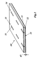
- Figure 1 is a perspective view of the basic structure of a sheet metal component of two (uncoated) sheets, which are interconnected by lap seams in the form of stitching.
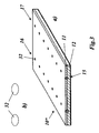
- Fig. 2 in a representation comparable to Figure 1 a sheet metal component of two sheets, which are connected by lap seams in the form of stitching, and one of which is provided on the outside with a heat-sensitive coating.
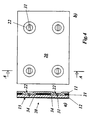
- Fig. 3 in a representation comparable to Fig. 2, a sheet metal component of two sheets which are interconnected by lap seams in the form of rows of welding points, and one of which is provided on the outside with a heat-sensitive coating (Fig. 3a), and the shape of the individual welding points (Fig. 3b);
- FIG. 4 shows in cross-section (FIG. 4a) and in the plan view from below (FIG. 4b) a sheet metal component of two sheets, one of which is provided on the outside with a heat-sensitive coating, and between which a sound and / or heat insulating Interposed is arranged;
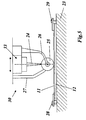
- FIG. 5 shows a side view of a system for producing the sheet-metal components from FIGS. 2 to 4;
- Fig. 6 seen the plant of Figure 5 in the direction of the weld.
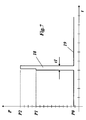
- FIG. 7 shows an exemplary beam power-over-time diagram of a laser during the production of a welding point according to FIG. 3.
- Fig. 1 the basic structure of a sheet metal component of two (uncoated) sheets or sheet metal parts is shown in a perspective view, which are interconnected by lap seams in the form of stitching.
- the sheet-metal component 10 comprises a first sheet 11 having a thickness d1 and a second sheet 12 having a thickness d2 which lie flat on one another.
- the two sheets 11, 12 are connected in the illustrated example by two welds 13 and 14, which are formed as individual weld seam sections 31 comprehensive stitching.
- the sheets 11, 12 may be steel but also aluminum or an aluminum alloy (e.g., AIMg3).
- the sheet metal component 10 'from FIG. 1 is shown as a flat component. However, it can of course also be curved or angled or have a different three-dimensional shape. This also applies to the planar configurations shown in the other figures.
- the individual weld seam sections 31 are introduced from the side of the first sheet metal 11 into the sheet stack. They are designed as lap seams which extend through the first metal sheet 11 into the second metal sheet 12 and have a depth T in the sheet stack which is between the thickness d 1 of the first metal sheet 11 and the sum d 1 + d 2 of the thicknesses of the two metal sheets 11 12 lies.
- a welding filler material in wire form is used, which may consist of AIMg4.5Mn for AIMg3 sheets, for example.
- a welding beam in particular a laser beam, is used, which is moved by means of a robot over the sheet metal stack 11, 12.
- the robot approaches the starting point of a weld seam section 31, switches on the beam power, then, with the beam power switched on, moves the line of the weld seam section 31 to the end point, switches the Beam power again, and finally moves with switched off beam power to the starting point of the next weld seam section.
- the traversing speed is in the range of, for example, 60 mm / s.
- the weld seam sections 31 may not only be straight, parallel to the weld seam, they may also be oblique to the weld, be curved or angled, or form closed circles or wavy lines to better withstand transverse forces acting on the weld.
- the weld seams 13, 14 as stitching seams with a limited depth T of the heat input in the two sheets 11, 12 and in particular in the lower plate 12 is limited. Accordingly, the occurrence of tarnish and dents in the region of the weld seam sections 31 can be counteracted.
- a heat-sensitive coating is, for example, a powder coating with a plastic powder, which is used to achieve a uniform, optically and haptically pleasing surface and for coloration and finds particular application when the sheet metal component is the inner lining of a rail vehicle or the like.
- the travel speed of the laser beam as well as the beam power and focus position must be selected depending on the material and the thickness of the two sheets or sheet metal parts so that the weld seams 13,14 sufficiently overlap without affecting the coated outer surface of the second sheet 12.
- the welding filler used was a wire of AIMg3.
- Stitching 13, 14 of the type shown in Fig. 1 and 2 are suitable Excellent for joining sheet metal components, especially if one of the two sheets or sheet metal parts is powder-coated. Restrictions result only in the speed of the method: The robot must first approach the predetermined starting point of a weld section 13, then the beam power is switched up, then the robot moves with the laser beam to the predetermined end point of the weld section 13, where the beam power is switched down again and the robot moves to the next predetermined starting point with the laser beam turned off.
- the approach of predetermined points in interaction with the local switching on and off of the laser beam takes control time in the robot control and thus limits the speed of the welding process.
- a significant acceleration of the welding process and thus a reduction in the production time can be achieved by the robot guiding unit being moved by the robot at constant speed along the line of the weld seam, and by forming a series of successive, spaced-apart welding points to form the weld seam, that the laser beam is switched up at certain times briefly (pulse-like).
- This then results in the sheet metal component "shown in Fig. 3, which in turn consists of the sheets 11 and 12 with the coating 15, but now by welding seams 16, 17 is joined, each consisting of a series of individual welding points 32 (Fig. The welding points 32, which according to FIG.
- 3b have an approximately oval shape due to the uniform traversing speed of the laser beam, are each generated by a pulse-shaped time curve P (t) of the beam power P over the time t, as shown in the diagram of FIG 7.
- the beam power P is in the range before and behind the pulse 18 is initially held at a ground level 19 of PO of, for example, 250W. This is advantageous for the diodes with which the laser source is pumped. If a welding point 32 is now to be generated, the jet power is raised in a pulse-like manner over a short period of time t1 and then lowered back to the base level 19.
- the start-up of the jet power P within the pulse 18 is preferably carried out in two stages: In a first stage, the jet power is raised to a first value P1 of, for example, 2200 Werhöht, and then further in the second stage to a P2 of eg 3000 Werhöht.
- P1 a first value of, for example, 2200 Werhöht
- P2 eg 3000 Werhöht.
- t1, PO, P1 and P2 may vary within a wider range and are intended to illustrate the order of magnitude only. It is important for the generation of the welding points 32, the gradual startup of the beam power P, which ensures that the beam power is coupled as far as possible in the sheets without being reflected.
- FIG. 5 Shown in Figures 5 and 6 within the welding system 30, the lower part of the am Robot arm attached and movable by means of the robot arm beam guide unit 33, from which the used for welding laser beam 24 emerges downwards.
- a wire feed 27 is provided in FIG. 5, through which wire-shaped welding additive can be supplied to the welding point.
- On the right side of the beam guiding unit 33 are laterally extending downwardly extending support arms 26, 26 'are arranged, which bend inwardly towards the lower end.
- a pressure roller 25, 25' rotatably mounted about a horizontal axis of rotation.
- the parallel pressure rollers 25, 25 ' take the laser beam 24 in the middle. They press when welding on the underlying Blechstapel11, 12, wherein the bent support arms 26, 26 'are bent elastically upwards and generate the necessary contact pressure.
- the two sheets or sheet metal parts 11, 12 to be welded are placed on a base 23 and fixed by means of detachable tensioning devices 28, 28 'and 29, 29' arranged at the edge relative to one another and to the base 23.
- the beam guiding unit 33 is then lowered so far onto the metal sheets 11, 12 for welding until the desired focus position of the laser beam 24 has been reached.
- the robot arm then moves with the beam guiding unit 33 from a preprogrammed line on which at regular intervals to form the weld 16,17 or 13, 14 welding points 32 or weld seam sections 31 are set.
- the inventive method makes it possible to connect a first uncoated sheet or sheet metal part with a second, on one side powder-coated sheet or sheet metal part directly and surface by beam welding without the coating of the second sheet is changed in an eye-catching way. But it can also be used to connect two sheets including an intermediate layer, which gives the finished sheet metal component in particular sound and / or thermal insulation properties.
- Such an intermediate layer may consist of a plastic or other material with corresponding properties and be porous or elastic, for example.
- a corresponding exemplary sheet-metal component 20 is shown in FIG. 4 in the plan view from the rear (FIG. 4b) and in section (FIG. 4a).
- the sheet metal component 20 in turn comprises a first sheet 11 and a second sheet 12, which is provided on the outside with a heat-sensitive coating 15. Between the two sheets 11, 12 an intermediate layer 21 is arranged, which can give the finished Blechbauteil20 depending on the selection various additional properties (thermal, acoustic, etc.).
- an intermediate layer 21 is arranged, which can give the finished Blechbauteil20 depending on the selection various additional properties (thermal, acoustic, etc.).
- holes 34 are provided in the intermediate layer 21 distributed over the surface, which may for example be punched and in the example of Fig. 4 are formed circular. The distribution and size of the holes 34 corresponding cup-shaped imprints 22 are introduced into the first sheet 11, the embossing depth corresponds approximately to the thickness of the intermediate layer 21.
- the intermediate layer 21 and the first sheet 11 are placed in the stack on the second plate 12 so that the embossings 22 in the first plate 11 through the holes 34 in the intermediate layer 21 through with the bottom on the second plate 12 touch down.
- the two sheets are then connected in the manner described above by stitching seams designed as lap seams, whose weld seam portions 31 each extend over the bottoms of the embossments 22.
- stitching seams designed as lap seams, whose weld seam portions 31 each extend over the bottoms of the embossments 22.
- the overall result of the invention is a method for the production of two sheet metal or sheet metal parts composite sheet metal components, which is characterized by a high flexibility of manufacturing, allows very short production times and leads to sheet metal components, the high optical and haptic quality very good mechanical and have other properties and can be used directly without post-processing.
Landscapes
- Physics & Mathematics (AREA)
- Optics & Photonics (AREA)
- Engineering & Computer Science (AREA)
- Plasma & Fusion (AREA)
- Mechanical Engineering (AREA)
- Laser Beam Processing (AREA)
- Laminated Bodies (AREA)
Applications Claiming Priority (1)
| Application Number | Priority Date | Filing Date | Title |
|---|---|---|---|
| CH21332004 | 2004-12-22 |
Publications (2)
| Publication Number | Publication Date |
|---|---|
| EP1674191A2 true EP1674191A2 (fr) | 2006-06-28 |
| EP1674191A3 EP1674191A3 (fr) | 2007-05-30 |
Family
ID=34974371
Family Applications (1)
| Application Number | Title | Priority Date | Filing Date |
|---|---|---|---|
| EP05111922A Withdrawn EP1674191A3 (fr) | 2004-12-22 | 2005-12-09 | Procédé de fabrication d'un objet comprenant deux toles ainsi que l'objet fabriqué. |
Country Status (1)
| Country | Link |
|---|---|
| EP (1) | EP1674191A3 (fr) |
Cited By (13)
| Publication number | Priority date | Publication date | Assignee | Title |
|---|---|---|---|---|
| WO2007060479A1 (fr) * | 2005-11-22 | 2007-05-31 | Gsi Group Limited | Soudage au laser d'aciers galvanises sans interstice a l'aide d'un laser semi-conducteur supermodule |
| DE102007058568A1 (de) * | 2007-11-29 | 2009-06-10 | Fraunhofer-Gesellschaft zur Förderung der angewandten Forschung e.V. | Verfahren zum defektfreien Schweißen metallischer Bauteile mit Elektronen- oder Laserstrahl |
| DE102008018130A1 (de) * | 2008-04-09 | 2009-10-15 | Volkswagen Ag | Verfahren zum Herstellen von Fahrzeugkarosserien |
| WO2013083892A1 (fr) * | 2011-12-08 | 2013-06-13 | Gaztransport Et Technigaz | Construction d'une membrane etanche a partir de plaques metalliques |
| DE102014209473A1 (de) * | 2014-05-20 | 2015-11-26 | Bayerische Motoren Werke Aktiengesellschaft | Verfahren zum Fügen von Bauteilen |
| DE102014017921A1 (de) * | 2014-12-04 | 2016-06-09 | Audi Ag | Bauteilanordnung sowie Verfahren zur Herstellung der Bauteilanordnung |
| DE102016222402A1 (de) * | 2016-11-15 | 2018-05-17 | Bayerische Motoren Werke Aktiengesellschaft | Verfahren zum Verschweißen von Bauteilen mittels Laserstrahlung und Verwendung des Verfahrens |
| DE102016222531A1 (de) * | 2016-11-16 | 2018-05-17 | Bayerische Motoren Werke Aktiengesellschaft | Verfahren zum Verschweißen von Bauteilen mittels Laserstrahlung und Schweißverbindung |
| IT201600132475A1 (it) * | 2016-12-29 | 2018-06-29 | L M N S R L | Impianto e metodo di saldatura con fasci laser |
| WO2019242995A1 (fr) * | 2018-06-20 | 2019-12-26 | Robert Bosch Gmbh | Procédé de liaison de deux pièces et composite de pièces |
| DE102012021755B4 (de) | 2012-11-07 | 2021-08-12 | Audi Ag | Laserstrahl-Schweißverfahren |
| WO2021245077A1 (fr) * | 2020-06-02 | 2021-12-09 | Fronius International Gmbh | Procédé de soudage |
| US12472580B2 (en) | 2022-06-01 | 2025-11-18 | Caterpillar Inc. | Laser handheld trimming and welding device |
Family Cites Families (3)
| Publication number | Priority date | Publication date | Assignee | Title |
|---|---|---|---|---|
| CA2209804A1 (fr) * | 1997-08-15 | 1999-02-15 | Hongping Gu | Methode de soudage au laser de toles d'acier zingue |
| ATE230327T1 (de) * | 1999-10-14 | 2003-01-15 | Carbodiam S A | Herstellungsverfahren einer schleifscheibe |
| US6646225B1 (en) * | 2003-04-02 | 2003-11-11 | General Motors Corporation | Method of joining galvanized steel parts using lasers |
-
2005
- 2005-12-09 EP EP05111922A patent/EP1674191A3/fr not_active Withdrawn
Cited By (22)
| Publication number | Priority date | Publication date | Assignee | Title |
|---|---|---|---|---|
| WO2007060479A1 (fr) * | 2005-11-22 | 2007-05-31 | Gsi Group Limited | Soudage au laser d'aciers galvanises sans interstice a l'aide d'un laser semi-conducteur supermodule |
| DE102007058568A1 (de) * | 2007-11-29 | 2009-06-10 | Fraunhofer-Gesellschaft zur Förderung der angewandten Forschung e.V. | Verfahren zum defektfreien Schweißen metallischer Bauteile mit Elektronen- oder Laserstrahl |
| DE102007058568B4 (de) * | 2007-11-29 | 2010-09-30 | Fraunhofer-Gesellschaft zur Förderung der angewandten Forschung e.V. | Verfahren zum defektfreien Schweißen metallischer Bauteile mit Elektronen- oder Laserstrahl |
| DE102008018130A1 (de) * | 2008-04-09 | 2009-10-15 | Volkswagen Ag | Verfahren zum Herstellen von Fahrzeugkarosserien |
| WO2013083892A1 (fr) * | 2011-12-08 | 2013-06-13 | Gaztransport Et Technigaz | Construction d'une membrane etanche a partir de plaques metalliques |
| FR2983751A1 (fr) * | 2011-12-08 | 2013-06-14 | Gaztransp Et Technigaz | Construction d'une membrane etanche a partir de plaques metalliques |
| CN104039495A (zh) * | 2011-12-08 | 2014-09-10 | 气体运输技术公司 | 金属板流体密封膜的构建 |
| CN104039495B (zh) * | 2011-12-08 | 2015-11-25 | 气体运输技术公司 | 金属板流体密封膜的构建 |
| DE102012021755B4 (de) | 2012-11-07 | 2021-08-12 | Audi Ag | Laserstrahl-Schweißverfahren |
| DE102014209473A1 (de) * | 2014-05-20 | 2015-11-26 | Bayerische Motoren Werke Aktiengesellschaft | Verfahren zum Fügen von Bauteilen |
| DE102014017921B4 (de) * | 2014-12-04 | 2017-10-12 | Audi Ag | Bauteilanordnung sowie Verfahren zur Herstellung der Bauteilanordnung |
| US9849758B2 (en) | 2014-12-04 | 2017-12-26 | Audi Ag | Component arrangement and method for producing the component arrangement |
| DE102014017921A1 (de) * | 2014-12-04 | 2016-06-09 | Audi Ag | Bauteilanordnung sowie Verfahren zur Herstellung der Bauteilanordnung |
| DE102016222402A1 (de) * | 2016-11-15 | 2018-05-17 | Bayerische Motoren Werke Aktiengesellschaft | Verfahren zum Verschweißen von Bauteilen mittels Laserstrahlung und Verwendung des Verfahrens |
| DE102016222531A1 (de) * | 2016-11-16 | 2018-05-17 | Bayerische Motoren Werke Aktiengesellschaft | Verfahren zum Verschweißen von Bauteilen mittels Laserstrahlung und Schweißverbindung |
| IT201600132475A1 (it) * | 2016-12-29 | 2018-06-29 | L M N S R L | Impianto e metodo di saldatura con fasci laser |
| WO2019242995A1 (fr) * | 2018-06-20 | 2019-12-26 | Robert Bosch Gmbh | Procédé de liaison de deux pièces et composite de pièces |
| CN112313029A (zh) * | 2018-06-20 | 2021-02-02 | 罗伯特·博世有限公司 | 用于连接两个构件的方法和构件复合体 |
| US11534864B2 (en) | 2018-06-20 | 2022-12-27 | Robert Bosch Gmbh | Method for connecting two components and component composite |
| WO2021245077A1 (fr) * | 2020-06-02 | 2021-12-09 | Fronius International Gmbh | Procédé de soudage |
| JP2023533148A (ja) * | 2020-06-02 | 2023-08-02 | フロニウス・インテルナツィオナール・ゲゼルシャフト・ミット・ベシュレンクテル・ハフツング | 溶接方法 |
| US12472580B2 (en) | 2022-06-01 | 2025-11-18 | Caterpillar Inc. | Laser handheld trimming and welding device |
Also Published As
| Publication number | Publication date |
|---|---|
| EP1674191A3 (fr) | 2007-05-30 |
Similar Documents
| Publication | Publication Date | Title |
|---|---|---|
| EP1125653B1 (fr) | Installation pour profiler avec une machine à profiler et un dispositif de soudage | |
| EP1674191A2 (fr) | Procédé de fabrication d'un objet comprenant deux toles ainsi que l'objet fabriqué. | |
| EP3487657B1 (fr) | Procédé pour produire des saillies ou des évidements en biais au niveau d'un bord de coupe d'une pièce en forme de plaque et produit programme informatique associé | |
| WO2011069621A1 (fr) | Procédé pour souder deux composants métalliques et agencement de liaison avec deux composants métalliques | |
| EP0069401A2 (fr) | Procédé de fabrication d'un matériau composite plant | |
| DE102009049750A1 (de) | Verfahren und Vorrichtung zum Schneiden von Material mittels eines modulierten Laserstrahls | |
| DE4104256A1 (de) | Verfahren zum herstellen von durch tiefziehen umgeformten formkoerpern, insbesondere von karosserieteilen fuer kraftfahrzeuge | |
| WO1998024569A1 (fr) | Procede pour la fabrication d'une piece moulee, ainsi que piece moulee ainsi fabriquee | |
| WO1996022855A1 (fr) | Procede pour l'assemblage de bandes assiste par laser | |
| EP3478445A1 (fr) | Procédé de soudage de pièces structurales | |
| DE2812415A1 (de) | Verfahren zur herstellung verschweisster blechprofile sowie vorrichtung zur durchfuehrung dieses verfahrens | |
| WO2015172797A1 (fr) | Procédé et dispositif d'assemblage pour relier deux pièces métalliques, notamment une pièce en acier et une pièce en aluminium, pièce composite correspondante | |
| DE3733568A1 (de) | Verfahren zur herstellung von schweissverbindungen an karosserieteilen und anderen blechteilen und robotersystem | |
| WO2020038504A2 (fr) | Procédé de soudage de bandes de tôles et dispositif pour produire une grande surface en utilisant un tel procédé | |
| EP0855235A1 (fr) | Procédé de fabrication de troncs de boíte en tôle | |
| DE102016222402A1 (de) | Verfahren zum Verschweißen von Bauteilen mittels Laserstrahlung und Verwendung des Verfahrens | |
| DE102017201872A1 (de) | Verfahren zum thermischen Fügen eines Bauteilverbundes und Bauteilverbund | |
| EP1847330B1 (fr) | Procédé de production d'un profil tubulaire à partir d'un matériau métallique en bande | |
| DE102005018727A1 (de) | Verfahren und Vorrichtung zum Verschweißen von zwei Werkstücken aus thermoplastischen Kunststoffen mittels Laserstrahlung | |
| EP0894037B1 (fr) | Procede pour la production de feuillards legers ou de toles legeres | |
| DE19623664C1 (de) | Verfahren und Vorrichtung zum Schweißen von Werkstücken mit Laserstrahlung | |
| DE102004005358B4 (de) | Verfahren zur Laserbearbeitung beschichteter Bleche und beschichtetes Blech | |
| EP0730508A1 (fr) | Procede de production d'ebauches tubulaires en tole mince ou en tole noire | |
| DE19852342C1 (de) | Verfahren zur Herstellung von Dosenrümpfen aus Blech für die Fertigung von Dosen | |
| DE10131883B4 (de) | Verfahren zum Verschweißen von Metallbauteilen |
Legal Events
| Date | Code | Title | Description |
|---|---|---|---|
| PUAI | Public reference made under article 153(3) epc to a published international application that has entered the european phase |
Free format text: ORIGINAL CODE: 0009012 |
|
| AK | Designated contracting states |
Kind code of ref document: A2 Designated state(s): AT BE BG CH CY CZ DE DK EE ES FI FR GB GR HU IE IS IT LI LT LU LV MC NL PL PT RO SE SI SK TR |
|
| AX | Request for extension of the european patent |
Extension state: AL BA HR MK YU |
|
| PUAL | Search report despatched |
Free format text: ORIGINAL CODE: 0009013 |
|
| AK | Designated contracting states |
Kind code of ref document: A3 Designated state(s): AT BE BG CH CY CZ DE DK EE ES FI FR GB GR HU IE IS IT LI LT LU LV MC NL PL PT RO SE SI SK TR |
|
| AX | Request for extension of the european patent |
Extension state: AL BA HR MK YU |
|
| 17P | Request for examination filed |
Effective date: 20071106 |
|
| AKX | Designation fees paid |
Designated state(s): AT BE BG CH CY CZ DE DK EE ES FI FR GB GR HU IE IS IT LI LT LU LV MC NL PL PT RO SE SI SK TR |
|
| 17Q | First examination report despatched |
Effective date: 20080118 |
|
| STAA | Information on the status of an ep patent application or granted ep patent |
Free format text: STATUS: THE APPLICATION IS DEEMED TO BE WITHDRAWN |
|
| 18D | Application deemed to be withdrawn |
Effective date: 20100701 |