EP1674657A1 - Procédé de construction d'un tunnel - Google Patents
Procédé de construction d'un tunnel Download PDFInfo
- Publication number
- EP1674657A1 EP1674657A1 EP04106796A EP04106796A EP1674657A1 EP 1674657 A1 EP1674657 A1 EP 1674657A1 EP 04106796 A EP04106796 A EP 04106796A EP 04106796 A EP04106796 A EP 04106796A EP 1674657 A1 EP1674657 A1 EP 1674657A1
- Authority
- EP
- European Patent Office
- Prior art keywords
- beams
- arch
- tunnel
- shaped structure
- ground
- Prior art date
- Legal status (The legal status is an assumption and is not a legal conclusion. Google has not performed a legal analysis and makes no representation as to the accuracy of the status listed.)
- Withdrawn
Links
- 238000000034 method Methods 0.000 title claims abstract description 24
- 239000002689 soil Substances 0.000 claims description 13
- 239000011440 grout Substances 0.000 claims description 3
- 238000007789 sealing Methods 0.000 claims description 3
- 239000000565 sealant Substances 0.000 claims 2
- 239000011796 hollow space material Substances 0.000 claims 1
- 238000009434 installation Methods 0.000 claims 1
- 239000000126 substance Substances 0.000 claims 1
- 210000002105 tongue Anatomy 0.000 description 8
- 238000005553 drilling Methods 0.000 description 3
- 239000012530 fluid Substances 0.000 description 2
- 239000000463 material Substances 0.000 description 2
- 235000013162 Cocos nucifera Nutrition 0.000 description 1
- 244000060011 Cocos nucifera Species 0.000 description 1
- 238000007796 conventional method Methods 0.000 description 1
- 239000000835 fiber Substances 0.000 description 1
- 238000011065 in-situ storage Methods 0.000 description 1
- 238000003780 insertion Methods 0.000 description 1
- 230000037431 insertion Effects 0.000 description 1
- 239000011148 porous material Substances 0.000 description 1
- 230000000284 resting effect Effects 0.000 description 1
- 239000011435 rock Substances 0.000 description 1
- 239000004576 sand Substances 0.000 description 1
- 239000007787 solid Substances 0.000 description 1
- XLYOFNOQVPJJNP-UHFFFAOYSA-N water Substances O XLYOFNOQVPJJNP-UHFFFAOYSA-N 0.000 description 1
Images



Classifications
-
- E—FIXED CONSTRUCTIONS
- E21—EARTH OR ROCK DRILLING; MINING
- E21D—SHAFTS; TUNNELS; GALLERIES; LARGE UNDERGROUND CHAMBERS
- E21D9/00—Tunnels or galleries, with or without linings; Methods or apparatus for making thereof; Layout of tunnels or galleries
- E21D9/005—Tunnels or galleries, with or without linings; Methods or apparatus for making thereof; Layout of tunnels or galleries by forcing prefabricated elements through the ground, e.g. by pushing lining from an access pit
-
- E—FIXED CONSTRUCTIONS
- E21—EARTH OR ROCK DRILLING; MINING
- E21B—EARTH OR ROCK DRILLING; OBTAINING OIL, GAS, WATER, SOLUBLE OR MELTABLE MATERIALS OR A SLURRY OF MINERALS FROM WELLS
- E21B7/00—Special methods or apparatus for drilling
- E21B7/20—Driving or forcing casings or pipes into boreholes, e.g. sinking; Simultaneously drilling and casing boreholes
- E21B7/201—Driving or forcing casings or pipes into boreholes, e.g. sinking; Simultaneously drilling and casing boreholes with helical conveying means
-
- E—FIXED CONSTRUCTIONS
- E21—EARTH OR ROCK DRILLING; MINING
- E21D—SHAFTS; TUNNELS; GALLERIES; LARGE UNDERGROUND CHAMBERS
- E21D11/00—Lining tunnels, galleries or other underground cavities, e.g. large underground chambers; Linings therefor; Making such linings in situ, e.g. by assembling
- E21D11/38—Waterproofing; Heat insulating; Soundproofing; Electric insulating
- E21D11/385—Sealing means positioned between adjacent lining members
-
- E—FIXED CONSTRUCTIONS
- E21—EARTH OR ROCK DRILLING; MINING
- E21D—SHAFTS; TUNNELS; GALLERIES; LARGE UNDERGROUND CHAMBERS
- E21D11/00—Lining tunnels, galleries or other underground cavities, e.g. large underground chambers; Linings therefor; Making such linings in situ, e.g. by assembling
- E21D11/38—Waterproofing; Heat insulating; Soundproofing; Electric insulating
- E21D11/385—Sealing means positioned between adjacent lining members
- E21D11/388—Sealing means positioned between adjacent lining members having longitudinal cavities communicating with the exterior on the outer side of the lining elements
Definitions
- the invention relates to a method of building a tunnel comprising an arch-shaped structure as well as to such tunnel.
- a particular application of the invention is to build the tunnel or underpass without causing surface disruption.
- One example thereof is to build a bicycle underpass below an existing rail track or highway without stopping the use and operation thereof.
- the invention provides a method according to claim 1.
- the method according to the invention is quite simple and may be used to build both short tunnels and longer tunnels in which a plurality of beams is driven into the ground aligned with each up to a desired length.
- the arch-shaped structure is formed by driving the elongate beams into the ground in a side-by-side relationship and during or after the creation of the arch-shaped structure, the soil below the arch is excavated in order to form the tunnel opening. If the beams are positioned with respect to each other such that a watertight seal is formed between them, there is no necessity to finish the beams on the inner side of the tunnel but the arch can be used right away. This makes the method according to the invention very simple.
- the floor and the foundation can be provided in different ways, depending on the underlying soil and the structure under which the tunnel should be made.
- the elongate beams are driven into the ground while the ground is removed in front of the beams, for example by means of an auger which can be used if the beams are hollow.
- the auger is inserted through the lumen in the beams and is moved with each beam in order to remove the soil in front of the beam and discharge it through the lumen in the beam.
- the beam is inserted into the ground by a combination of pressing or jacking and drilling. Due to the small cross section of the building elements (i.e. beams) and due to the manner of driving in the building elements, the soil disruption is kept to a minimum.
- the invention also includes a tunnel comprising a plurality of elongate beams positioned side by side in a watertight manner to create an arch-shaped structure forming the roof of the tunnel, a foundation connected to the arch-shaped structure and a floor.
- a tunnel is simple in structure and is easy to build into the ground. The soil and the structures above the tunnel to be excavated are not disrupted so that for example a road above the tunnel can remain in operation during building of the tunnel. If the subsoil is such that no foundation is required, the floor and arch-shaped structure can be supported directly on the subsoil.
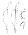
- Figs. 1, 3 and 5 are longitudinal sectional views of three different embodiments of a tunnel according to the invention.
- Figs. 2, 4 and 6 are front views of the tunnel embodiments of Figs. 1, 3 and 5.
- Fig. 7 is an enlarged scale front view of an elongate beam for forming the arch-shaped structure in the tunnel according to Figs. 1-6.
- Figs. 8-10 show, on an even larger scale, three embodiments of possible seals between two adjacent beams in the arch-shaped structure.
- Figs. 11 and 12 illustrate two stages in the operation of driving the elongate beams of the arch-shaped structure into the ground.
- Figs. 13 and 14 illustrate in a front view a manner of forming the arch-shaped structure by means of the elongate beams.
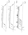
- Figs. 15 - 19 illustrate several stages in providing a floor and foundation in the embodiment of the tunnel according to Figs. 3 and 4.
- Fig. 20 is a sectional view according to the line XX-XX in Fig. 19.
- FIG. 1 - 6 show several embodiments of a tunnel or underpass.
- the tunnel is used to underpass a traffic road or railroad which is built on a bank, so that the tunnel to be excavated is made at ground level. It should be understood, however, that the tunnel and the methods of building one could also be used underground.
- the tunnel includes as main part an arch-shaped structure 1 which is formed of elongate beams 2.
- These beams 2 are of a substantially rectangular shape, but include an arc shape such that the arch will be formed automatically if the beams 2 are in abutting relationship.
- they are provided with a tong-and-groove system, wherein one side of each beam is provided with a tongue 3, whereas the opposite side is provided with a groove 4 in which the tongue 3 of the next beam 2 fits.
- the other two sides of the beam 2 are slightly curved, so that when the beams 2 have been fitted to each other there is formed a smooth surface on the inner side of the arch-shaped structure 1.
- the beams 2 are hollow and have a lumen 5 extending in longitudinal direction through the whole length of each beam 2. The function and advantages thereof will be described later on.
- the tunnel may further include a floor 6 and a foundation 7.
- the foundation 7 is positioned at the ends of the tunnel and in this case laterally and longitudinally outside the arch-shaped structure 1.
- the foundation 7 comprises in this embodiment foundation piles 8 and supporting heads 9 resting on the piles 8.
- the transverse supporting heads 9 support the ends of an arch-shaped end beam 10 created around the ends of the elongate beams 2 and being fixed thereto.
- This end beams 10 may also support or be connected to a further superstructure 11 provided on the bank B.
- pre-tensioning elements such as cables or rods through the lumen 5 in the beams 2, which are stretched and fixed outside the beams 2, for example to the end beams 10. These pre-tensioning elements will increase the strength of the arch-shaped structure 1.
- the floor 6 is part of the foundation and for this purpose, the floor 6 is fixed on its lateral sides 2 at least to the lower beams 2 of the arch-shaped structure 1 and is supported on foundation piles 12.
- the floor 6 may be made of prefabricated elements or may be cast in situ. The method of building this embodiment of the tunnel according to the invention will be explained later on with reference to Figs. 15 - 19.
- Figs. 5 and 6 show an embodiment of the tunnel according to the invention, in which the underground or subsoil functions as the foundation of the tunnel.
- the underground consists of non-settling material, such as rock or sand.
- the floor 6 and the arch-shaped structure 1 are formed directly on the underground or subsoil.
- Figs. 7 - 10 show the cross-sectional shape of the elongate beams 2 in more detail. If the arch shape of the structure 1 has a constant curvature, all beams 2 may have the same cross section, but in principle it is possible to create an arch which has different curvatures along its cross-section and in that case beams 2 with different cross sections will be used along the length of the arch.
- Figs. 8 - 10 show three embodiments of a seal between adjacent beams 2 in order to obtain water tightness of the arch-shaped structure 1. In that case, no finishing or sealing layers are necessary on the inside or outside of the arch-shaped structure.
- a porous tube or hose 13 for example made of coconut fibre material, is provided between the tongue 3 and groove 4 of the adjacent beams 2 and preferably this tube or hose 13 is accommodated partly in a small notch 14 in the tongue 3 of the beams 2.
- the tube 13 is introduced simultaneously with one of the adjacent beams 2.
- a sealing fluid such as grout or the like, is injected into the tube 13 and this fluid fills the tube 13 but will also leave the tube through the pores in order to fill the space between the adjacent beams 2. In this way there is created a watertight seal between the beams 2 in the arch-shaped structure 1.
- Fig. 9 shows the second embodiment wherein a solid rubber seal 15 is positioned under tension between the tongue 3 and groove 4 of adjacent beams 2 in order to create a watertight seal.
- Fig. 10 shows a third embodiment which is a combination of the embodiments of Figs. 8 and 9.
- a rubber seal 15 is provided in a notch 14 in the tongue 3 of one of the beams 2 and this rubber seal 15 may be filled in order to either create pressure from the inside to close off the space between the adjacent beams 2 or to be enable the rubber seal to accommodate movements and forces between the adjacent beams 2.
- the arch-shaped structure 1 is created by subsequently driving a plurality of elongate beams 2 substantially horizontally into the ground, in this case into the ground forming a bank B, in a side-by-side relationship.
- a driving apparatus 16 In order to drive each beam 2 into the ground, a driving apparatus 16 is used which uses a combination of drilling and pressing or jacking to drive the beams 2 into the ground.
- a pilot rod 17 In order to guide the beams 2 through the ground, a pilot rod 17 is driven into the ground by means of the driving apparatus 16. Said pilot rod 17 has a small diameter and has a pointed tip in order to cut through the ground easily. This piloting operation is illustrated in Fig. 11.
- Fig. 12 shows the next step in the driving operation and in this step, the beams 2 are driven into the ground guided around the pilot rod 17.
- a ground drill or auger 18 which is hollow so as to be guided around the pilot rod 17 and which is introduced in the ground together with the beam.
- the auger 18 is inserted into the beam 2 through the lumen 5 therein and this auger 18 projects slightly from the driving end of the beam 2 so as to remove the ground in front of the beam 2 and to discharge this ground or soil through the lumen 5 to a position behind the beam 2.
- the beam 2 is introduced into the ground by a combination of drilling and pressing as this beam 2 is forced into the ground by pressure exerted by the driving apparatus 16.
- a plurality of beams 2 are driven into the ground in alignment with each other such that the combined length of the aligned beams 2 corresponds with the desired length of the arch-shaped structure. Different lengths of the beams 2 may be used or the end beams 2 can be cut off at the desired length if the length of the arch-shaped structure 1 varies along the arch.
- the creation of the arch-shaped structure 1 is started with a centre beam 2' which does no have a tongue 3 and groove 4 at opposite sides, but has a groove 4 on opposite sides.
- the cross section of the tunnel is symmetrical with the tongues 3 of the beams 2 being directed to the centre of the arch on both sides of the centre beam 2'.
- the halves of the arch-shaped structure 1 are created one after the other.
- other ways of creating the arch are conceivable.
- Figs. 15 - 19 illustrate a method of excavating the tunnel and providing the floor and foundation of the tunnel, in particular in the embodiments according to Figs. 3 and 4.
- Fig. 15 shows the situation after the arch-shaped structure 1 has been created. Then the soil within the arch-shaped structure 1 is removed in a segment S on one end of the arch-shaped structure 1.
- a floor 6 is created in this excavated segment S and in case the floor 6 is founded, foundation piles 12 are first driven into the soil before the floor 6 is provided thereon. If the floor 6 is finished in this first segment S, the next segment S is excavated as is illustrated in Fig. 17. This next segment S is neighbouring the first segment S. As is illustrated in Fig. 18, the floor 6 and the foundation 7 are then provided in this second segment S. This operation is continued until all of the soil within the arch-shaped structure 1 has been excavated and the floor 7 has been provided at the bottom of this excavated tunnel.
- the tunnel is of greater length or if loads on the arch-shaped structure 1 are relatively high, it is possible to form one or more cambered trusses 19 at one or more positions between the ends of the arch-shaped structure 1 to improve the strength of this structure.
- This truss 19 is shown in Figs. 19 and 20.
- the invention provides a method with which a tunnel can be built in a simple and quick manner without disturbing the soil above it.
- the cross-sectional shape of the arch may be varied, and more resemble a rounded rectangle.
- the vertical support for beams by the adjacent beam will be less in the centre of the tunnel, so it is desirable then to provide a supporting arch.
- the beams are driven into the ground subsequently, but it is also conceivable that more than one beam is inserted at a time.
Landscapes
- Engineering & Computer Science (AREA)
- Mining & Mineral Resources (AREA)
- Structural Engineering (AREA)
- Geology (AREA)
- Life Sciences & Earth Sciences (AREA)
- Geochemistry & Mineralogy (AREA)
- General Life Sciences & Earth Sciences (AREA)
- Civil Engineering (AREA)
- Architecture (AREA)
- Environmental & Geological Engineering (AREA)
- Physics & Mathematics (AREA)
- Fluid Mechanics (AREA)
- Excavating Of Shafts Or Tunnels (AREA)
Priority Applications (1)
| Application Number | Priority Date | Filing Date | Title |
|---|---|---|---|
| EP04106796A EP1674657A1 (fr) | 2004-12-21 | 2004-12-21 | Procédé de construction d'un tunnel |
Applications Claiming Priority (1)
| Application Number | Priority Date | Filing Date | Title |
|---|---|---|---|
| EP04106796A EP1674657A1 (fr) | 2004-12-21 | 2004-12-21 | Procédé de construction d'un tunnel |
Publications (1)
| Publication Number | Publication Date |
|---|---|
| EP1674657A1 true EP1674657A1 (fr) | 2006-06-28 |
Family
ID=34930100
Family Applications (1)
| Application Number | Title | Priority Date | Filing Date |
|---|---|---|---|
| EP04106796A Withdrawn EP1674657A1 (fr) | 2004-12-21 | 2004-12-21 | Procédé de construction d'un tunnel |
Country Status (1)
| Country | Link |
|---|---|
| EP (1) | EP1674657A1 (fr) |
Cited By (4)
| Publication number | Priority date | Publication date | Assignee | Title |
|---|---|---|---|---|
| CN101864959B (zh) * | 2009-04-17 | 2013-06-12 | 中铁工程设计咨询集团有限公司 | 一种地下车站主体结构的暗挖施工方法 |
| JP2016141946A (ja) * | 2015-01-30 | 2016-08-08 | 株式会社大林組 | パイル案内用ガイド部材およびトンネル地盤支持方法 |
| JP2017082550A (ja) * | 2015-10-30 | 2017-05-18 | 大成建設株式会社 | 地下構造物の構築方法、地下構造物および継手構造 |
| CN107288642A (zh) * | 2017-06-20 | 2017-10-24 | 北京市政建设集团有限责任公司 | Pba施工工艺 |
Citations (11)
| Publication number | Priority date | Publication date | Assignee | Title |
|---|---|---|---|---|
| GB1289550A (fr) * | 1969-12-30 | 1972-09-20 | ||
| DE2250635A1 (de) * | 1972-10-16 | 1974-04-25 | Nishimatsu Constr Co Ltd | Verfahren zum bau eines tunnels |
| US4009579A (en) * | 1975-12-08 | 1977-03-01 | Patzner Delbert M | Method for constructing a tunnel or underpass |
| US4139320A (en) * | 1976-08-20 | 1979-02-13 | Japanese National Railways | Process for excavating and constructing tunnel and excavating device |
| JPS5458919A (en) * | 1977-10-19 | 1979-05-12 | Japan National Railway | Method of constructing tunnel under roadway |
| JPH03156094A (ja) * | 1989-11-13 | 1991-07-04 | Higashi Nippon Riyokaku Tetsudo Kk | 路盤下横断円形断面構造物およびその施工方法 |
| JPH11247275A (ja) * | 1998-02-27 | 1999-09-14 | Mitsubishi Rayon Co Ltd | 止水材 |
| JP2000337093A (ja) * | 1999-05-26 | 2000-12-05 | Nihon Samicon Kk | アーチ形中空構造物 |
| JP2001123791A (ja) * | 1999-10-28 | 2001-05-08 | Shin Gijutsu Koei Kk | 掘削機及び掘削方法 |
| JP2003176698A (ja) * | 2001-12-11 | 2003-06-27 | Hayakawa Rubber Co Ltd | トンネル構造の補修工法及びトンネル構造 |
| JP2004011341A (ja) * | 2002-06-10 | 2004-01-15 | Nippon Grease Nipple Kk | 薬剤注入用ホース |
-
2004
- 2004-12-21 EP EP04106796A patent/EP1674657A1/fr not_active Withdrawn
Patent Citations (11)
| Publication number | Priority date | Publication date | Assignee | Title |
|---|---|---|---|---|
| GB1289550A (fr) * | 1969-12-30 | 1972-09-20 | ||
| DE2250635A1 (de) * | 1972-10-16 | 1974-04-25 | Nishimatsu Constr Co Ltd | Verfahren zum bau eines tunnels |
| US4009579A (en) * | 1975-12-08 | 1977-03-01 | Patzner Delbert M | Method for constructing a tunnel or underpass |
| US4139320A (en) * | 1976-08-20 | 1979-02-13 | Japanese National Railways | Process for excavating and constructing tunnel and excavating device |
| JPS5458919A (en) * | 1977-10-19 | 1979-05-12 | Japan National Railway | Method of constructing tunnel under roadway |
| JPH03156094A (ja) * | 1989-11-13 | 1991-07-04 | Higashi Nippon Riyokaku Tetsudo Kk | 路盤下横断円形断面構造物およびその施工方法 |
| JPH11247275A (ja) * | 1998-02-27 | 1999-09-14 | Mitsubishi Rayon Co Ltd | 止水材 |
| JP2000337093A (ja) * | 1999-05-26 | 2000-12-05 | Nihon Samicon Kk | アーチ形中空構造物 |
| JP2001123791A (ja) * | 1999-10-28 | 2001-05-08 | Shin Gijutsu Koei Kk | 掘削機及び掘削方法 |
| JP2003176698A (ja) * | 2001-12-11 | 2003-06-27 | Hayakawa Rubber Co Ltd | トンネル構造の補修工法及びトンネル構造 |
| JP2004011341A (ja) * | 2002-06-10 | 2004-01-15 | Nippon Grease Nipple Kk | 薬剤注入用ホース |
Non-Patent Citations (6)
| Title |
|---|
| PATENT ABSTRACTS OF JAPAN vol. 015, no. 386 (M - 1163) 30 September 1991 (1991-09-30) * |
| PATENT ABSTRACTS OF JAPAN vol. 1999, no. 14 22 December 1999 (1999-12-22) * |
| PATENT ABSTRACTS OF JAPAN vol. 2000, no. 15 6 April 2001 (2001-04-06) * |
| PATENT ABSTRACTS OF JAPAN vol. 2000, no. 22 9 March 2001 (2001-03-09) * |
| PATENT ABSTRACTS OF JAPAN vol. 2003, no. 10 8 October 2003 (2003-10-08) * |
| PATENT ABSTRACTS OF JAPAN vol. 2003, no. 12 5 December 2003 (2003-12-05) * |
Cited By (4)
| Publication number | Priority date | Publication date | Assignee | Title |
|---|---|---|---|---|
| CN101864959B (zh) * | 2009-04-17 | 2013-06-12 | 中铁工程设计咨询集团有限公司 | 一种地下车站主体结构的暗挖施工方法 |
| JP2016141946A (ja) * | 2015-01-30 | 2016-08-08 | 株式会社大林組 | パイル案内用ガイド部材およびトンネル地盤支持方法 |
| JP2017082550A (ja) * | 2015-10-30 | 2017-05-18 | 大成建設株式会社 | 地下構造物の構築方法、地下構造物および継手構造 |
| CN107288642A (zh) * | 2017-06-20 | 2017-10-24 | 北京市政建设集团有限责任公司 | Pba施工工艺 |
Similar Documents
| Publication | Publication Date | Title |
|---|---|---|
| CN109209397B (zh) | 穿越高角度逆冲富水富砂断层隧道施工方法 | |
| KR101671123B1 (ko) | 선지보와 후지보를 이용한 터널 공법 및 이에 적합한 장치 | |
| JP5103516B2 (ja) | 大断面トンネルの先支保トンネル工法 | |
| CN109931077B (zh) | 用于隧道修复的支护系统及其施工方法 | |
| CN110374633A (zh) | 隧道穿越松散体的洞口段施工方法 | |
| KR20170007975A (ko) | Forepoling Board와 지반보강을 이용하여 곡선선형을 이루는 비개착식 터널 시공방법 | |
| KR20170061061A (ko) | 선지보와 후지보를 이용한 터널 공법 및 이에 적합한 장치 | |
| KR20080082892A (ko) | 배수 구조를 갖는 세그먼트에 의한 원형 지보공 구조 및이를 이용한 실드터널을 시공하는 방법 | |
| JP4317322B2 (ja) | アーチ支持構造 | |
| CN107288642A (zh) | Pba施工工艺 | |
| CN118030143A (zh) | 一种适用于倾斜上软下硬地层的隧道非对称支护施工方法 | |
| CN111305851A (zh) | 一种基于插梁冻结法的软土地层地铁车站扩建方法及结构 | |
| KR100800028B1 (ko) | 프론트 잭킹공법을 이용한 터널 구축방법 | |
| JP4296549B2 (ja) | 地中支保構造体およびその施工方法ならびにトンネル工法 | |
| CN116335757A (zh) | 一种负泊松比结构充填挡墙及其施工方法 | |
| CN110424459A (zh) | 一种不影响现有道路通行的下穿通道施工工艺 | |
| KR100626820B1 (ko) | 천층 터널 공법 | |
| DE4412880A1 (de) | Verfahren zum Auffahren eines unterirdischen Hohlraumes | |
| CN108979645A (zh) | 桥下复合曲线双层综合管廊交通环廊暗挖暨逆作施工工艺 | |
| US5871307A (en) | Pre-cast concrete panel wall | |
| EP1426495A2 (fr) | Méthode et dispositif pour construire un tunnel ou une tranchée | |
| KR102394424B1 (ko) | 터널 구축용 함체 및 이를 이용한 터널의 시공방법 | |
| KR101523948B1 (ko) | 기존 구조물 하부의 지하구조물 구축 공법 | |
| KR100768473B1 (ko) | 직진성 및 유도배수가 가능한 지중압입체를 이용한지하구조물 시공방법 | |
| JPS6317999B2 (fr) |
Legal Events
| Date | Code | Title | Description |
|---|---|---|---|
| PUAI | Public reference made under article 153(3) epc to a published international application that has entered the european phase |
Free format text: ORIGINAL CODE: 0009012 |
|
| AK | Designated contracting states |
Kind code of ref document: A1 Designated state(s): AT BE BG CH CY CZ DE DK EE ES FI FR GB GR HU IE IS IT LI LT LU MC NL PL PT RO SE SI SK TR |
|
| AX | Request for extension of the european patent |
Extension state: AL BA HR LV MK YU |
|
| 17P | Request for examination filed |
Effective date: 20061222 |
|
| 17Q | First examination report despatched |
Effective date: 20070123 |
|
| AKX | Designation fees paid |
Designated state(s): AT BE BG CH CY CZ DE DK EE ES FI FR GB GR HU IE IS IT LI LT LU MC NL PL PT RO SE SI SK TR |
|
| STAA | Information on the status of an ep patent application or granted ep patent |
Free format text: STATUS: THE APPLICATION IS DEEMED TO BE WITHDRAWN |
|
| 18D | Application deemed to be withdrawn |
Effective date: 20080904 |