EP1674754A2 - Dispositif d'actionnement pour un embrayage d'un véhicule automobile - Google Patents
Dispositif d'actionnement pour un embrayage d'un véhicule automobile Download PDFInfo
- Publication number
- EP1674754A2 EP1674754A2 EP05026294A EP05026294A EP1674754A2 EP 1674754 A2 EP1674754 A2 EP 1674754A2 EP 05026294 A EP05026294 A EP 05026294A EP 05026294 A EP05026294 A EP 05026294A EP 1674754 A2 EP1674754 A2 EP 1674754A2
- Authority
- EP
- European Patent Office
- Prior art keywords
- speed
- throttle member
- hydraulic actuator
- actuator according
- hydraulic
- Prior art date
- Legal status (The legal status is an assumption and is not a legal conclusion. Google has not performed a legal analysis and makes no representation as to the accuracy of the status listed.)
- Withdrawn
Links
- 239000012530 fluid Substances 0.000 claims abstract description 44
- 238000002485 combustion reaction Methods 0.000 claims description 15
- 230000005291 magnetic effect Effects 0.000 claims description 11
- 230000003213 activating effect Effects 0.000 abstract 1
- 230000006835 compression Effects 0.000 description 11
- 238000007906 compression Methods 0.000 description 11
- 238000001514 detection method Methods 0.000 description 11
- 238000007789 sealing Methods 0.000 description 11
- 238000000034 method Methods 0.000 description 10
- 230000008569 process Effects 0.000 description 10
- 230000009471 action Effects 0.000 description 5
- 230000004913 activation Effects 0.000 description 5
- 230000008878 coupling Effects 0.000 description 4
- 238000010168 coupling process Methods 0.000 description 4
- 238000005859 coupling reaction Methods 0.000 description 4
- 238000013461 design Methods 0.000 description 4
- 230000009467 reduction Effects 0.000 description 4
- 230000001105 regulatory effect Effects 0.000 description 4
- 238000013459 approach Methods 0.000 description 3
- 230000005540 biological transmission Effects 0.000 description 2
- 230000009849 deactivation Effects 0.000 description 2
- 230000007423 decrease Effects 0.000 description 2
- 238000011156 evaluation Methods 0.000 description 2
- XEEYBQQBJWHFJM-UHFFFAOYSA-N Iron Chemical group [Fe] XEEYBQQBJWHFJM-UHFFFAOYSA-N 0.000 description 1
- 230000008901 benefit Effects 0.000 description 1
- 230000008859 change Effects 0.000 description 1
- 238000010276 construction Methods 0.000 description 1
- 230000007547 defect Effects 0.000 description 1
- 230000001419 dependent effect Effects 0.000 description 1
- 238000011161 development Methods 0.000 description 1
- 230000018109 developmental process Effects 0.000 description 1
- 238000006073 displacement reaction Methods 0.000 description 1
- 230000000694 effects Effects 0.000 description 1
- 230000002349 favourable effect Effects 0.000 description 1
- 239000003302 ferromagnetic material Substances 0.000 description 1
- 238000009434 installation Methods 0.000 description 1
- 239000012212 insulator Substances 0.000 description 1
- 230000010355 oscillation Effects 0.000 description 1
- 230000002093 peripheral effect Effects 0.000 description 1
Images


Classifications
-
- F—MECHANICAL ENGINEERING; LIGHTING; HEATING; WEAPONS; BLASTING
- F16—ENGINEERING ELEMENTS AND UNITS; GENERAL MEASURES FOR PRODUCING AND MAINTAINING EFFECTIVE FUNCTIONING OF MACHINES OR INSTALLATIONS; THERMAL INSULATION IN GENERAL
- F16D—COUPLINGS FOR TRANSMITTING ROTATION; CLUTCHES; BRAKES
- F16D48/00—External control of clutches
- F16D48/02—Control by fluid pressure
-
- F—MECHANICAL ENGINEERING; LIGHTING; HEATING; WEAPONS; BLASTING
- F16—ENGINEERING ELEMENTS AND UNITS; GENERAL MEASURES FOR PRODUCING AND MAINTAINING EFFECTIVE FUNCTIONING OF MACHINES OR INSTALLATIONS; THERMAL INSULATION IN GENERAL
- F16D—COUPLINGS FOR TRANSMITTING ROTATION; CLUTCHES; BRAKES
- F16D25/00—Fluid-actuated clutches
- F16D25/08—Fluid-actuated clutches with fluid-actuated member not rotating with a clutching member
- F16D25/088—Fluid-actuated clutches with fluid-actuated member not rotating with a clutching member the line of action of the fluid-actuated members being distinctly separate from the axis of rotation
-
- F—MECHANICAL ENGINEERING; LIGHTING; HEATING; WEAPONS; BLASTING
- F16—ENGINEERING ELEMENTS AND UNITS; GENERAL MEASURES FOR PRODUCING AND MAINTAINING EFFECTIVE FUNCTIONING OF MACHINES OR INSTALLATIONS; THERMAL INSULATION IN GENERAL
- F16D—COUPLINGS FOR TRANSMITTING ROTATION; CLUTCHES; BRAKES
- F16D48/00—External control of clutches
- F16D48/06—Control by electric or electronic means, e.g. of fluid pressure
- F16D48/066—Control of fluid pressure, e.g. using an accumulator
-
- F—MECHANICAL ENGINEERING; LIGHTING; HEATING; WEAPONS; BLASTING
- F16—ENGINEERING ELEMENTS AND UNITS; GENERAL MEASURES FOR PRODUCING AND MAINTAINING EFFECTIVE FUNCTIONING OF MACHINES OR INSTALLATIONS; THERMAL INSULATION IN GENERAL
- F16D—COUPLINGS FOR TRANSMITTING ROTATION; CLUTCHES; BRAKES
- F16D48/00—External control of clutches
- F16D48/02—Control by fluid pressure
- F16D2048/0215—Control by fluid pressure for damping of pulsations within the fluid system
-
- F—MECHANICAL ENGINEERING; LIGHTING; HEATING; WEAPONS; BLASTING
- F16—ENGINEERING ELEMENTS AND UNITS; GENERAL MEASURES FOR PRODUCING AND MAINTAINING EFFECTIVE FUNCTIONING OF MACHINES OR INSTALLATIONS; THERMAL INSULATION IN GENERAL
- F16D—COUPLINGS FOR TRANSMITTING ROTATION; CLUTCHES; BRAKES
- F16D48/00—External control of clutches
- F16D48/02—Control by fluid pressure
- F16D2048/0221—Valves for clutch control systems; Details thereof
-
- F—MECHANICAL ENGINEERING; LIGHTING; HEATING; WEAPONS; BLASTING
- F16—ENGINEERING ELEMENTS AND UNITS; GENERAL MEASURES FOR PRODUCING AND MAINTAINING EFFECTIVE FUNCTIONING OF MACHINES OR INSTALLATIONS; THERMAL INSULATION IN GENERAL
- F16D—COUPLINGS FOR TRANSMITTING ROTATION; CLUTCHES; BRAKES
- F16D2500/00—External control of clutches by electric or electronic means
- F16D2500/10—System to be controlled
- F16D2500/102—Actuator
- F16D2500/1026—Hydraulic
- F16D2500/1027—Details about the hydraulic valves
-
- F—MECHANICAL ENGINEERING; LIGHTING; HEATING; WEAPONS; BLASTING
- F16—ENGINEERING ELEMENTS AND UNITS; GENERAL MEASURES FOR PRODUCING AND MAINTAINING EFFECTIVE FUNCTIONING OF MACHINES OR INSTALLATIONS; THERMAL INSULATION IN GENERAL
- F16D—COUPLINGS FOR TRANSMITTING ROTATION; CLUTCHES; BRAKES
- F16D2500/00—External control of clutches by electric or electronic means
- F16D2500/30—Signal inputs
- F16D2500/302—Signal inputs from the actuator
- F16D2500/3026—Stroke
-
- F—MECHANICAL ENGINEERING; LIGHTING; HEATING; WEAPONS; BLASTING
- F16—ENGINEERING ELEMENTS AND UNITS; GENERAL MEASURES FOR PRODUCING AND MAINTAINING EFFECTIVE FUNCTIONING OF MACHINES OR INSTALLATIONS; THERMAL INSULATION IN GENERAL
- F16D—COUPLINGS FOR TRANSMITTING ROTATION; CLUTCHES; BRAKES
- F16D2500/00—External control of clutches by electric or electronic means
- F16D2500/30—Signal inputs
- F16D2500/306—Signal inputs from the engine
- F16D2500/3067—Speed of the engine
-
- F—MECHANICAL ENGINEERING; LIGHTING; HEATING; WEAPONS; BLASTING
- F16—ENGINEERING ELEMENTS AND UNITS; GENERAL MEASURES FOR PRODUCING AND MAINTAINING EFFECTIVE FUNCTIONING OF MACHINES OR INSTALLATIONS; THERMAL INSULATION IN GENERAL
- F16D—COUPLINGS FOR TRANSMITTING ROTATION; CLUTCHES; BRAKES
- F16D2500/00—External control of clutches by electric or electronic means
- F16D2500/50—Problem to be solved by the control system
- F16D2500/502—Relating the clutch
- F16D2500/50293—Reduction of vibrations
-
- F—MECHANICAL ENGINEERING; LIGHTING; HEATING; WEAPONS; BLASTING
- F16—ENGINEERING ELEMENTS AND UNITS; GENERAL MEASURES FOR PRODUCING AND MAINTAINING EFFECTIVE FUNCTIONING OF MACHINES OR INSTALLATIONS; THERMAL INSULATION IN GENERAL
- F16D—COUPLINGS FOR TRANSMITTING ROTATION; CLUTCHES; BRAKES
- F16D2500/00—External control of clutches by electric or electronic means
- F16D2500/50—Problem to be solved by the control system
- F16D2500/504—Relating the engine
- F16D2500/5048—Stall prevention
-
- F—MECHANICAL ENGINEERING; LIGHTING; HEATING; WEAPONS; BLASTING
- F16—ENGINEERING ELEMENTS AND UNITS; GENERAL MEASURES FOR PRODUCING AND MAINTAINING EFFECTIVE FUNCTIONING OF MACHINES OR INSTALLATIONS; THERMAL INSULATION IN GENERAL
- F16D—COUPLINGS FOR TRANSMITTING ROTATION; CLUTCHES; BRAKES
- F16D2500/00—External control of clutches by electric or electronic means
- F16D2500/50—Problem to be solved by the control system
- F16D2500/512—Relating to the driver
- F16D2500/5126—Improving response to driver inputs
Definitions
- the invention relates to a hydraulic actuating device for a friction clutch of a motor vehicle according to the preamble of patent claim 1.
- a generic actuator with a throttle member is described for example in DE 43 34 551 C2, wherein in a valve housing of the throttle member, a valve body is slidably held in the form of a disc-shaped closing member whose formed as a sealing surface end face abuts by a compression spring against a corresponding sealing surface of the valve housing.
- the compression spring counteracts the flow of hydraulic fluid from the master cylinder to the slave cylinder, wherein the closing member increases the flow area when acted upon by the hydraulic fluid in this flow direction.
- the known throttle member is automatically activated at each pedal actuation depending on the flow direction and possibly on the flow velocity of the fluid, shown as operating conditions only open and closed can be.
- the known damper must also be optimized so that a compromise between the lowest still permissible pedal return time at low temperature and the achieved minimum reduction in torque peak at high temperature is achieved.
- the well-known throttle member is able to reduce the fluid channel cross-section and thus the engagement speed, which helps to avoid unacceptably high engagement speeds, in particular during a gear change.
- driving conditions also occur frequently, in particular during start-up, in which, despite the presence of a throttle member and a reduced engagement speed during engagement, torque surges are introduced into the drive train because the engine speed is not adapted to the particular situation, which unfavorably leads to the internal combustion engine stalling can. If this occurs, for example, on a slope or in a traffic area with a high traffic volume, for example in an inner city intersection area, this can endanger the vehicle occupants and other road users and lead to accidents.
- the invention has the object to improve a clutch actuation system by simple means to the effect that the risk of stalling of the internal combustion engine during engagement of the vehicle friction clutch is reduced.
- the invention solves the problem set with a hydraulic actuator, which has the features of claim 1.
- the inventor first recognized that not only the engagement speed is critical for smooth engagement, but rather that the engagement speed, i. the advancing movement of the axially movable clutch pressure plate and the instantaneous power of the internal combustion engine, i. the product of speed and torque, need to be matched.
- the invention proposes assigning a drive device to the throttle element, with which the throttle element is freely activatable when at least one predetermined operating state of the motor vehicle is present.
- an operating state detection device is provided for detecting this condition. This means that the throttle member is not generally activated when engaging, but only when this actually requires the specific operating situation.
- the throttle member can be activated in the sense of reducing the Fluidkanalqueritess and delay the engagement briefly and unnoticed by the driver until the engine has again assumed a stable, remote from dying speed and the further closing of the friction clutch is certainly possible.
- the throttle member is tuned to a comparison with a normal starting increased engine speed and activated.
- the throttle member may e.g. be operated intermittently and thus a time-average desired fluid channel cross-section and a resulting fluid flow velocity for the critical driving situation can be realized.
- a start-up but also generally a clutch operation does not need to be controlled by the dynamic balance of driving and clutch pedal, but can run much simpler for the driver at the request, by the clutch pedal off when activated throttle member is relieved without special feeling and the engagement is controlled only by means of the accelerator pedal by the driver.
- the proposed hydraulic actuator thus provides a start-up assistant for relieving the driver in this regard.
- the freely controllable throttle member arranged in the hydraulic actuating device can also be controlled or regulated as a peak torque limiter or as an attenuator for reducing a clutch pedal leg.
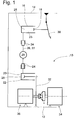
- a hydraulic actuating device 10 for actuating a friction clutch 12 is shown schematically, which is arranged on a chassis 14 of a motor vehicle and wherein a master cylinder 16 with a piston 18 and a slave cylinder 20 are arranged with a piston 22, which together via plug-in couplings or hydraulic coupling elements 24 are connected to a fluid-filled hydraulic line 26 through a fluid channel 27 and form a common pressure chamber 28.
- the piston 18 of the master cylinder 16 can be actuated by a Kupplngspedal 30, whereupon the piston 22 of the slave cylinder 20 moves and controls a clutch fork 32 for disengaging the clutch 12 on a motor 34 designed as a drive unit.
- the clutch 12 is connected on the input side to the output shaft of the internal combustion engine 34 and on the output side to a manual transmission 36.
- a freely activatable throttle member 29 for temporary influence, ie a reduction of the fluid channel cross section for throttling the fluid flow as required and thus provided for reducing the engagement speed, the structure and operation of which will be described in detail below.
- the throttle member 29 may be carried out separately depending on the installation situation and connected via hydraulic coupling elements 24 at an arbitrary position with the hydraulic line 26 and one of the pressure cylinders 16, 20 or alternatively integrally with the hydraulic line 26 or one of the pressure cylinders 16, 20 are shown.
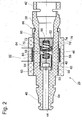
- Fig. 2 shows an axial sectional view of a freely activatable throttle member 29 for arrangement within the hydraulic pressure chamber.
- the throttle member 29 comprises a plastic housing 38 with plug connectors 40, 42 on both sides for easy mounting in the hydraulic actuator 10.
- the housing 38 has a multi-stepped axial through hole 44 as part of the fluid channel 27, in the middle portion 46, a piston 48 axially slidable between two frontally fixed to the housing stops 50, 52 is displaced.
- the piston 48 has in the interior also in the axial direction of a through hole 54 with respect to the fluid channel 27 reduced cross section, which is frontally extended to form a receiving chamber 56 for at least partially receiving a serving as a return element compression spring 58.
- a plurality of axial webs 60 are formed, which rest for the play-free guidance in the bore portion 46 and define between them a corresponding number of axially extending fluid channels 62.
- the piston 48 is axially symmetrical, ie that on the side facing away from the compression spring 58 a receiving chamber 56 is executed.
- the piston 48 is supported in the position shown in Fig. 2 on the left of a run with the housing 38 stop 50, but the passage of fluid through both the central through-hole 54 and on the outer channels 62 is unhindered possible.
- the total cross section of the channels 54, 62 on the piston 48 is at least sized so that it corresponds to the cross section of an adjacent, located in the housing 38 channel portion 64, whereby a fluid flowing in the fluid channel 27 fluid unthrottled through the piston 48 and can flow around.
- the axial side opposite disc 52 formed as a stop has analogous to the piston 48, a further receiving chamber 66 for at least partially receiving the compression spring 58 and a contrast reduced diameter through hole 68 for the passage of the hydraulic fluid, wherein the diameter is also such that essentially no Reduction of the fluid channel cross-section in the hydraulic system 10 is recorded.
- the stop 52 is conveniently designed as a separate, cylindrical plastic element and is pressed sealingly in the housing 38 after the introduction of the piston 48 and the compression spring 58.
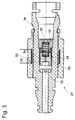
- a sealing element 70 can additionally be arranged on the end region facing the piston 48, which engages with a radially inwardly directed annular web 72 in an annular groove 74 introduced on the outer circumferential surface of the stop 52 and with a first sealing region 76 against the housing 38 and with a second sealing region 78, the stop 52 can seal against a radially outer annular web 80 of the piston 48 in its abutment against the stop 52, as shown in Fig. 3 can be seen ge on stop 52 can seal, as this is apparent in Fig. 3. In this position, the outer channels 62 are blocked and a passage of fluid is only possible through the central channel 54, whereby a significant throttling of the fluid flow is achieved. If a sealing element 70 is provided, this is preassembled on the stop 52, whereupon both parts 52, 70 can be pressed together into the housing 38.
- the piston 48 is disposed within the hydraulic actuator 10 so that it assumes a starting position shown in FIG. 2 and only under the action of an external, predetermined force, preferably in at least one predetermined operating condition of the vehicle against the action of the compression spring 58 in the direction of Stop 52, ie in the direction of the slave cylinder 20 can shift and thereby reduces the fluid channel cross-section and the fluid flow velocity and even completely suppressed in the absence of the bore 54.
- the fluid channel cross section can also assume freely selectable values between a minimum and a maximum value, which result when the piston is only partially displaced to the stop 52.
- the pressure spring 58 arranged between the piston 48 and the stop 52 is designed so that its spring force is sufficiently high to keep the piston 48 against the flow at maximum flow velocity and a low-temperature unfavorable fluid viscosity in FIG. 2 at the left stop 50. as long as the external force does not work.
- the piston 48 should also be displaceable against the fluid flow within a very short time by the stop 52 in the direction of the left-side abutment 50 in order to enlarge the fluid channel cross section.
- the throttle member 29 assumes in the illustrated construction a normal-open position, whereby this is designed fail-safe. Thus, even with a defect of the throttle member 29, a controlled and safe operation of the hydraulic actuator 10 and the vehicle is guaranteed.
- the throttle member 29 is formed as a solenoid valve in the illustrated embodiment.
- the piston 48 is at least partially made of a ferromagnetic material by this example is formed as plastic-coated iron ring core, which is acted upon by a magnetic field of the housing 38 disposed magnetic coil 82 with an axial force, whereby the described adjusting movement of the piston 48 regardless of the flow direction of the fluid within the pressure chamber 28 is executable.
- the working as a closing coil solenoid 82 is embedded in a separate insulating body 84 which is pushed onto the housing 38 and held captive with a latching connection 86 thereto. It is also possible to apply the magnetic coil 82 directly on the housing 38 and to shed with this.
- the throttle member 29 can continuously adjust the fluid channel cross section between a maximum value and a minimum value as required, given a corresponding current application of the closing coil 82.
- the axial position of the magnetic coil 82 is fixed to the housing 38 so that in the energized state, a magnetic force is exerted on the piston 48 in the direction of the stop 52, whereby the piston 48 against the force of the return spring 58 to the stop 52 and possibly to the Sealing member 70 is pressed to completely lock the channels 62 located at the piston outer area for the fluid.
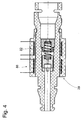
- a second, working as an opening coil solenoid 88 may be arranged, which when energized, the piston 48 alone or with the assistance of the return spring from the stop 52 and this detaches can shift back to the starting position shown in FIG.
- the opening coil 88 is likewise embedded in the insulating body 84 and arranged axially adjacent to the closing coil 82 at the level of the left-side stop 50.
- both coils 82, 88 can simultaneously be supplied with current in a defined manner in order to adapt the adjustment speed of the piston 48 to a desired level in this way.
- the coils 82, 88 are shown electrically in FIG. 5 via a driving device, i. a control electronics 90 connected to the vehicle electrical system 92, wherein the control electronics 90 receives a command to activate the closing 82 and the opening coil 88 only in the presence of a certain operating state of a detection device 94 operating state of the motor vehicle.
- a driving device i. a control electronics 90 connected to the vehicle electrical system 92, wherein the control electronics 90 receives a command to activate the closing 82 and the opening coil 88 only in the presence of a certain operating state of a detection device 94 operating state of the motor vehicle.
- the operating state detection device 94 can optionally communicate with a sensor 96 for detecting the piston position in the master cylinder 16 and the control unit 102 of the internal combustion engine 34, whereby the latter also simultaneously obtains data from a speed sensor 98 for determining the crankshaft speed of the internal combustion engine 34 and from a throttle position sensor 100 is possible. These sensors are already present in motor vehicles anyway, so there are no additional requirements in this regard.
- the operating state detection device 94 is also connected via the engine control unit 102 to a central vehicle control 104 and thus can optionally also take into account the vehicle speed when determining the operating state.
- the signals from the sensors 96, 98, 100 are detected by the operating state detection device 94 and monitored by means of a logic circuit for the presence of a predetermined operating state.
- the operation of the internal combustion engine 34 can also be influenced by the operating state detection device 94 via the signal line to the control device 102, for example by the throttle valve position being correspondingly influenced during a power or torque request.
- the signals of various sensors alone or used together for evaluation and activation of the throttle member 29 can also be influenced by the operating state detection device 94 via the signal line to the control device 102, for example by the throttle valve position being correspondingly influenced during a power or torque request.
- both magnetic coils 82, 88 are not energized.
- the piston 48 is pressed by the compression spring 58 against the housing stop 50, whereby for the passing through the throttle member 29 fluid, the maximum channel cross-section formed by the channels 62 at the piston outer region and the central bore 54 is available.
- the operating state detection device 94 recognizes that the risk of stalling of the internal combustion engine 34 is no longer present, whereupon the magnetic coil 82 is again de-energized becomes.
- the compression spring 58 moves the piston 48 again in its initial position to the housing stop 54, whereby the action on the hydraulic clutch actuation system 10 is repealed.
- the activation and deactivation of the throttle member 29 as a starting assistant can be done relatively high frequency and often as needed.
- the flow cross-section of the piston bore 54 can be selected to be even smaller and, in the case of a highly dynamic design of the actuation system 10, even the bore 54 can be completely dispensed with.
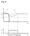
- Fig. 6 the time course of a starting operation at idle speed (n_Leerlauf) of the internal combustion engine 34 is shown with and without working as a starting assistant throttle member 29, which initially has only one closing coil 82.
- Curve a describes the course of the engine speed at a too fast engagement speed when starting at idle speed (n_Leerlauf), wherein the complete engagement of the clutch 12 at an engagement speed (n_Eingriff) below the idle speed (n_Leerlauf) takes place.
- the power of the internal combustion engine 34 is not sufficient to accelerate the vehicle in the short engagement time to a speed corresponding to the minimum engine speed in the engaged gear. The speed thus falls below a critical, the shutdown from the engine representing speed (n_mot off), wherein the engine 34 is strangled.
- Curve b describes a starting process under identical boundary conditions, but with the throttle member 29 being activated upon reaching the engagement speed (n_engineering) as a starting assist. From this point on, the approach assist reduces the engagement speed.
- the motor 34 has sufficient time to accelerate the vehicle by means of slipping clutch 12 to a sufficiently high speed, without the engine speed drops below the cut-off (n_mot off).
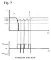
- FIG. 7 shows the course of a starting operation at idling speed (n_level run) without and with throttle element 29 operating as a starting assist, which has a closing coil 82 and additionally an opening coil 88.
- the curve c corresponds to the curve of the curve a in Fig. 6, which describes the course of the engine speed at too fast engagement speed when starting at idle speed (n_Leerlauf).
- the engine power is not sufficient to accelerate the vehicle in the short engagement time to a speed that corresponds to the minimum engine speed in the engaged gear.
- the speed falls below the cut-off limit (n_mot off) of the motor 34, whereupon it is strangled.
- Curve d describes the course of the engine speed with activated start-up assistant with additional energization of the closing coil 88.
- the engagement speed (n_Eingriff)
- damper member 29 due to the design of the piston 48 with a through hole 54 with smaller flow cross-section
- the engine speed stabilizes faster;
- the speed drop with respect to the engagement limit (n_Eingriff) is lower and the speed increases comparatively quickly again above a specified speed (n_ ⁇ réelle) for pulsed activation of the opening coil 88 of the start-up assistant. Since the vehicle has not yet been accelerated to a sufficiently high speed, the speed drops again, whereupon the closing coil 82 is reactivated.
- the process is repeated until the vehicle has been accelerated by slipping clutch 12 to a sufficiently high speed.
- the speed range necessary for control can be kept lower by the engagement limit (n_engagement). This is particularly advantageous when the idle speed (n_eerlauf) is close to the shutdown (n_mot off) of the motor 34.
- Fig. 8 the time course of a starting operation at an increased speed compared to idle speed without and with working as approach assistant damper member 29 is shown, this initially has only one closing coil 82.
- the curve e describes the course of the engine speed at a too fast engagement speed when starting with an increased speed compared to the idling speed (n_Leerlauf).
- the excessive engagement speed can arise, for example, due to slippage from the clutch pedal 30.
- the engine power is not sufficient to accelerate the vehicle in the short engagement time to a speed that is the minimum engine speed in the engaged gear equivalent.
- the speed falls below the cut-off limit (n_mot off) of the motor 34, whereby it is strangled.
- the curve f describes a course of the engine speed with activated start-up assistant. Once the engagement speed (n_Eingriff) is reached, there is an activation of the throttle member 29, which then reduces the engagement speed.
- the motor 34 thus has sufficient time to accelerate the vehicle by means of slipping clutch 12 to a sufficiently high speed, without the speed drops below the cut-off (n_ mot off).
- Fig. 9 describes the time course of a starting process at a relative to idle speed (n_Leerlauf) increased speed without and working as a starting assistant throttle member 29, which has a closing coil 82 and additionally an opening coil 88.
- curve g shows the course of the engine speed at an engagement speed that is too fast when starting up at a speed which is higher than the idling speed (n_speed).
- This too high engagement speed can arise, for example, by slipping off the clutch pedal 30.
- the engine power is not sufficient to accelerate the vehicle in the short engagement time to a speed that corresponds to the minimum engine speed in the engaged gear.
- the speed falls below the cut-off limit (n_mot off) of the motor 34, whereupon it is strangled.
- Curve h describes this course of the engine speed with activated, two-pulley running start-up assistant.
- the assistant is reactivated. The process is repeated until the vehicle has been accelerated by slipping clutch 12 to a sufficiently high speed.
- the speed bandwidth required for the control can be kept lower by the engagement limit (n_engagement). This is particularly advantageous when the idle speed (n_Leerlauf) is close to the shutdown (n_mot_aus) of the motor 34.
- a corresponding signal of the throttle position sensor 100 can also be used by the operating state detection device 94 as a decision aid and as a result alternatively or additionally to the activation the throttle member 29 via the controller 102 of the engine 34, a short-term increased power from the engine 34 are retrieved.
- the throttle member 29 may also take over the function of a peak torque limiter (PTL) for reducing a torque peak load of the drive train during engagement in an arrangement according to FIG. 5.
- PTL peak torque limiter
- the closing coil 82 is energized.
- the engagement speed of the clutch 12 and thus the load of the drive train during engagement can be maintained at a permissible level.
- the return speed of the clutch pedal 12 is reduced only during the modulation time of the clutch 12 and not throughout the pedal travel, resulting in a comfort gain.
- the control of the PTL functionality results in a largely constant reduction of the torque peak when engaging regardless of the temperature.
- "controllable PTL" of the throttle member 29 is recommended due to the high dynamic demand also a version with an opening coil 88.
- the need for a peak torque limiter in the vehicle always arises when due to an almost sudden closing of the clutch 12, a very high angular momentum is impulsively introduced into the drive train, which could lead to damage.
- a controlled PTL has the advantage that the return speed of the clutch pedal is reduced only in the modulation zone of the clutch 12 and not throughout the pedal travel. Furthermore, the temperature of the fluid and thus its viscosity is largely irrelevant to the function.
- the engagement speed is of decisive importance for the angular momentum introduced into the drive train of the vehicle via the friction clutch 12. Since a high engagement speed is reflected as a steep gradient in the course of the engine speed, can be used as the sensor signal for a regulated PTL turn the determined by the speed sensor 98 engine speed.
- a delay value is calculated therefrom, compared with a setpoint value and, if the result is correct, the closing coil 82 is energized, whereupon the engagement speed is reduced and the engine speed decreases more slowly.
- the closing coil 82 is switched off and the opening coil 88 is briefly energized.
- the speed delay value re-takes the preset limit, the cycle repeats.
- the evaluation of the position sensor 96 of the master cylinder is also useful for the function of the controlled peak torque limiter because it can avoid operating cases in which the closing coil 82 is unnecessarily energized, while a disengaging process could take place and thus the closing force of the coil with the foot in addition would have to be overcome with.
- the operating cases in question are, for example, strong braking with the clutch closed 12 and simultaneous disengagement or strong racing of the engine 34 at idle and simultaneous disengagement.
- another moving element of the hydraulic clutch actuator 10 can be sensed.
- Fig. 10 the curve of the rotational speed n of the motor 34 in a starting operation at an increased speed compared to idle speed and sudden engagement, e.g. in the operating case "starting at high speed and pedal locks", initially shown without the use of a Peak Torque Limiter.
- corresponding curves for the disengagement or clutch pedal travel s and for the torque M_antrieb the drive train are shown.
- Fig. 10 also applies to the operating case "vehicle rolls at high speed in the disengaged state with idle speed, then pedal locks".
- the steep gradient of the Ausschweges illustrates a high closing speed of the clutch 12.
- the steep drop in the engine speed n causes the introduction of a high torque peak in the drive train, which settles back to normal in the form of a damped oscillation. Due to the magnitude of the torque peak, damage to a component in the drive train may result.
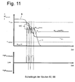
- FIG. 11 describes, corresponding to FIG. 10, the course of a starting operation at an engine speed n increased in comparison with idling speed n_level and sudden engagement, wherein a throttle element 29 regulated as a peak torque limiter engages.
- the closing coil 82 is energized from reaching a preset deceleration limit value of the engine speed.
- the engine speed decreases more slowly from this point on until it reaches a second limit for the engine Deactivation of the closing coil 82 and the short-term energization of the opening coil 88 reached. From this point on, the number of revolutions decelerates again above the closing limit and the closing coil 82 is energized again.
- the closing coil 82 and the opening coil 88 in alternation with a current, z.b. in the form of rectangular pulses or peaks.
- a current z.b. in the form of rectangular pulses or peaks.
- operations are also possible in which the magnetic coils 82, 88 are partially superimposed with a continuously changing current applied.
- the throttle member 29 can operate as an attenuator during normal driving operation with the clutch fully closed 12 and a sufficiently high engine speed and substantially prevent the passage of fluid by energizing the closing coil 82.
- the diameter of the bore 54 in the piston 48 is particularly small or completely waive this.
- a relatively small bore 54 acts as an effective throttle for one of crankshaft axial vibrations Micro flow. In this way, vibrations on the clutch pedal 30 are effectively reduced, which the driver can feel when he turns his foot on this. As soon as the clutch pedal 30 is actuated, the energization of the coil 82 is switched off again.
- a path signal of the master cylinder 16 or of another moving element of the hydraulic actuating system 10 is necessary as an input variable for the operating state detection device 94.
- the closing coil 82 of the throttle member 29 is energized for this function whenever the engine speed is between the idle speed and the maximum engine speed and the clutch pedal 30 is in almost unactuated position. The displacement of the clutch pedal 30 by slightly stopping the foot can be tolerated.
- a signal for the pedal position either a switching point signal or a continuous signal can be used. If the clutch pedal 30 is moved in the direction of disengaging, the closing coil 82 is de-energized.
Landscapes
- Engineering & Computer Science (AREA)
- General Engineering & Computer Science (AREA)
- Physics & Mathematics (AREA)
- Fluid Mechanics (AREA)
- Mechanical Engineering (AREA)
- Hydraulic Clutches, Magnetic Clutches, Fluid Clutches, And Fluid Joints (AREA)
Applications Claiming Priority (1)
| Application Number | Priority Date | Filing Date | Title |
|---|---|---|---|
| DE102004062554A DE102004062554A1 (de) | 2004-12-24 | 2004-12-24 | Hydraulische Betätigungseinrichtung für eine Reibungskupplung eines Kraftfahrzeuges |
Publications (2)
| Publication Number | Publication Date |
|---|---|
| EP1674754A2 true EP1674754A2 (fr) | 2006-06-28 |
| EP1674754A3 EP1674754A3 (fr) | 2009-10-21 |
Family
ID=35954090
Family Applications (1)
| Application Number | Title | Priority Date | Filing Date |
|---|---|---|---|
| EP05026294A Withdrawn EP1674754A3 (fr) | 2004-12-24 | 2005-12-02 | Dispositif d'actionnement pour un embrayage d'un véhicule automobile |
Country Status (2)
| Country | Link |
|---|---|
| EP (1) | EP1674754A3 (fr) |
| DE (1) | DE102004062554A1 (fr) |
Cited By (3)
| Publication number | Priority date | Publication date | Assignee | Title |
|---|---|---|---|---|
| EP2345825A1 (fr) * | 2010-01-19 | 2011-07-20 | Nissan Motor Manufacturing (UK) Ltd. | Appareil et procédé pour contrôler le fonctionnement d'un embrayage de véhicule |
| CN107117024A (zh) * | 2016-02-25 | 2017-09-01 | 通用汽车环球科技运作有限责任公司 | 用于操作机动车离合器的操作装置 |
| FR3061525A1 (fr) * | 2017-01-05 | 2018-07-06 | Renault S.A.S | Limiteur de debit de commande hydraulique d’embrayage |
Families Citing this family (9)
| Publication number | Priority date | Publication date | Assignee | Title |
|---|---|---|---|---|
| DE102008023145A1 (de) | 2008-05-09 | 2009-01-22 | Daimler Ag | Betätigungseinrichtung sowie Kraftfahrzeugkupplung |
| DE102010006058A1 (de) | 2009-02-12 | 2010-08-19 | Luk Lamellen Und Kupplungsbau Beteiligungs Kg | Hydraulisches Kupplungs- oder Bremsbetätigungssystem |
| DE102009010029A1 (de) | 2009-02-21 | 2010-08-26 | Dr.Ing.H.C. F. Porsche Ag | Kupplungsbetätigungseinrichtung |
| DE102011010878A1 (de) | 2011-02-10 | 2012-08-16 | Schaeffler Technologies Gmbh & Co. Kg | Schaltbarer Spitzenmomentbegrenzer |
| DE102013210262A1 (de) | 2012-06-20 | 2013-12-24 | Schaeffler Technologies AG & Co. KG | Hydraulisches Betätigungssystem |
| DE102014206956A1 (de) * | 2013-05-10 | 2014-11-13 | Schaeffler Technologies Gmbh & Co. Kg | Sensorsystem mit integrierter Führung in einem hydrostatischen Kupplungsausrücker |
| DE102013211770A1 (de) * | 2013-06-21 | 2014-12-24 | Robert Bosch Gmbh | Verfahren zum Betreiben eines Kraftfahrzeugs |
| DE102014012722A1 (de) | 2014-08-27 | 2016-03-03 | GM Global Technology Operations LLC (n. d. Ges. d. Staates Delaware) | Drosselglied für eine Betätigungseinrichtung zum Betätigen einer Kraftfahrzeug-Kupplung |
| DE102015207797A1 (de) * | 2015-04-28 | 2016-11-03 | Schaeffler Technologies AG & Co. KG | Momentenbegrenzer für ein Betätigungssystem |
Citations (1)
| Publication number | Priority date | Publication date | Assignee | Title |
|---|---|---|---|---|
| DE4344551A1 (de) | 1993-12-24 | 1995-06-29 | Henkel Kgaa | Verwendung von Allylaminophenolen in Oxidationsfärbemitteln |
Family Cites Families (5)
| Publication number | Priority date | Publication date | Assignee | Title |
|---|---|---|---|---|
| EP0082893A1 (fr) * | 1981-12-29 | 1983-07-06 | Volvo Car B.V. | Dispositif de commande pour mécanisme de transmission |
| DE3736584A1 (de) * | 1987-10-29 | 1989-05-18 | Bayerische Motoren Werke Ag | Hydraulische betaetigungseinrichtung |
| DE4334551C2 (de) * | 1993-10-11 | 2002-09-26 | Luk Lamellen & Kupplungsbau | Hydraulische Betätigungseinrichtung |
| GB9824362D0 (en) * | 1998-11-07 | 1998-12-30 | Rover Group | A motor vehicle and a clutch actuation system therfor |
| AU2003247257A1 (en) * | 2002-07-18 | 2004-02-09 | Luk Lamellen Und Kupplungsbau Beteiligungs Kg | Hydraulic actuation system |
-
2004
- 2004-12-24 DE DE102004062554A patent/DE102004062554A1/de not_active Withdrawn
-
2005
- 2005-12-02 EP EP05026294A patent/EP1674754A3/fr not_active Withdrawn
Patent Citations (1)
| Publication number | Priority date | Publication date | Assignee | Title |
|---|---|---|---|---|
| DE4344551A1 (de) | 1993-12-24 | 1995-06-29 | Henkel Kgaa | Verwendung von Allylaminophenolen in Oxidationsfärbemitteln |
Cited By (4)
| Publication number | Priority date | Publication date | Assignee | Title |
|---|---|---|---|---|
| EP2345825A1 (fr) * | 2010-01-19 | 2011-07-20 | Nissan Motor Manufacturing (UK) Ltd. | Appareil et procédé pour contrôler le fonctionnement d'un embrayage de véhicule |
| CN107117024A (zh) * | 2016-02-25 | 2017-09-01 | 通用汽车环球科技运作有限责任公司 | 用于操作机动车离合器的操作装置 |
| FR3061525A1 (fr) * | 2017-01-05 | 2018-07-06 | Renault S.A.S | Limiteur de debit de commande hydraulique d’embrayage |
| EP3346153A1 (fr) * | 2017-01-05 | 2018-07-11 | RENAULT s.a.s. | Limiteur de debit de commande hydraulique d'embrayage |
Also Published As
| Publication number | Publication date |
|---|---|
| EP1674754A3 (fr) | 2009-10-21 |
| DE102004062554A1 (de) | 2006-07-06 |
Similar Documents
| Publication | Publication Date | Title |
|---|---|---|
| DE19910049B4 (de) | Antriebssystem | |
| EP1999392B1 (fr) | Procédé de commande d'un embrayage automatique à frottement | |
| EP0970319B1 (fr) | Dispositif et procede pour reduire le patinage lors de la commande d'une transmission a changement de vitesses continu dans un vehicule a moteur | |
| EP1674754A2 (fr) | Dispositif d'actionnement pour un embrayage d'un véhicule automobile | |
| DE19751225A1 (de) | Vorrichtung zur Ansteuerung eines Drehmomentübertragungssystems | |
| DE10225262A1 (de) | Kupplungsbetätigungsvorrichtung sowie Verfahren zum ermitteln von Kupplungsparametern | |
| WO2000075536A1 (fr) | Procede pour faire fonctionner une unite d'actionnement d'une boite de vitesse automatisee | |
| DE2657524A1 (de) | Steuervorrichtung fuer eine durch einen hydraulik-stellzylinder betaetigbare kraftfahrzeugkupplung | |
| EP1740852B1 (fr) | Agencement de soupape de commande pour la commande d'un embrayage de demarrage d'une boite de vitesses automatique | |
| DE4231563C2 (de) | Steuerungseinrichtung für eine automatisch gesteuerte Kupplung | |
| DE19633420A1 (de) | Verfahren und Vorrichtung zur hydraulischen Betätigung einer Kupplung, insbesondere für Kraftfahrzeuge | |
| EP1938004B1 (fr) | Ensemble soupape de commande pour la commande d'un embrayage de demarrage d'une boite de vitesses automatique | |
| DE10250729A1 (de) | Betätigungseinrichtung für eine Kupplung, Antriebsstrang eines Kraftfahrzeugs und Verfahren zum Betrieb des Antriebsstrangs | |
| EP1775449B1 (fr) | Ligne de transmission pour véhicule et méthode pour l'utilisation d'une telle ligne de transmission | |
| DE2336927C2 (de) | Regelventil für den Arbeitsdruck eines automatisch geschalteten Getriebes für Fahrzeuge, insbesondere Kraftfahrzeuge | |
| DE3504001C2 (fr) | ||
| DE68911955T2 (de) | Steuerung für ein stufenlos verstellbares Getriebe. | |
| EP0929409B1 (fr) | Dispositif et procede de reglage du rapport de transmission dans une transmission a rapports variables en continu | |
| EP0912361B1 (fr) | Embrayage a commande automatique | |
| EP2632758A1 (fr) | Dispositif de réglage de la commande de puissance d'un moteur à combustion interne et procédé de commande de puissance d'un moteur à combustion interne | |
| DE19922694A1 (de) | Verfahren zur Steuerung eines Automatgetriebes eines Kraftfahrzeuges | |
| DE10232500A1 (de) | Messeinrichtung und Messverfahren für ein Kraftfahrzeug | |
| DE102016100733A1 (de) | Steuerung für ein stufenloses Getriebe | |
| WO1995029350A1 (fr) | Systeme de commande de la pression | |
| DE102013210396A1 (de) | Verfahren zum Betreiben eines Kraftfahrzeugs mit einer manuellen Kupplungs-anordnung |
Legal Events
| Date | Code | Title | Description |
|---|---|---|---|
| PUAI | Public reference made under article 153(3) epc to a published international application that has entered the european phase |
Free format text: ORIGINAL CODE: 0009012 |
|
| AK | Designated contracting states |
Kind code of ref document: A2 Designated state(s): AT BE BG CH CY CZ DE DK EE ES FI FR GB GR HU IE IS IT LI LT LU LV MC NL PL PT RO SE SI SK TR |
|
| AX | Request for extension of the european patent |
Extension state: AL BA HR MK YU |
|
| PUAL | Search report despatched |
Free format text: ORIGINAL CODE: 0009013 |
|
| AK | Designated contracting states |
Kind code of ref document: A3 Designated state(s): AT BE BG CH CY CZ DE DK EE ES FI FR GB GR HU IE IS IT LI LT LU LV MC NL PL PT RO SE SI SK TR |
|
| AX | Request for extension of the european patent |
Extension state: AL BA HR MK YU |
|
| AKX | Designation fees paid | ||
| STAA | Information on the status of an ep patent application or granted ep patent |
Free format text: STATUS: THE APPLICATION IS DEEMED TO BE WITHDRAWN |
|
| 18D | Application deemed to be withdrawn |
Effective date: 20100422 |
|
| REG | Reference to a national code |
Ref country code: DE Ref legal event code: 8566 |