EP1674789A2 - Unité de lampe avec une source de lumière, un guide de lumière et une zone permettant de réorienter la lumière - Google Patents
Unité de lampe avec une source de lumière, un guide de lumière et une zone permettant de réorienter la lumière Download PDFInfo
- Publication number
- EP1674789A2 EP1674789A2 EP05025844A EP05025844A EP1674789A2 EP 1674789 A2 EP1674789 A2 EP 1674789A2 EP 05025844 A EP05025844 A EP 05025844A EP 05025844 A EP05025844 A EP 05025844A EP 1674789 A2 EP1674789 A2 EP 1674789A2
- Authority
- EP
- European Patent Office
- Prior art keywords
- light
- lighting unit
- unit according
- deflection
- light source
- Prior art date
- Legal status (The legal status is an assumption and is not a legal conclusion. Google has not performed a legal analysis and makes no representation as to the accuracy of the status listed.)
- Granted
Links
Images


Classifications
-
- G—PHYSICS
- G02—OPTICS
- G02B—OPTICAL ELEMENTS, SYSTEMS OR APPARATUS
- G02B6/00—Light guides; Structural details of arrangements comprising light guides and other optical elements, e.g. couplings
- G02B6/0001—Light guides; Structural details of arrangements comprising light guides and other optical elements, e.g. couplings specially adapted for lighting devices or systems
- G02B6/0011—Light guides; Structural details of arrangements comprising light guides and other optical elements, e.g. couplings specially adapted for lighting devices or systems the light guides being planar or of plate-like form
- G02B6/0013—Means for improving the coupling-in of light from the light source into the light guide
- G02B6/0015—Means for improving the coupling-in of light from the light source into the light guide provided on the surface of the light guide or in the bulk of it
- G02B6/0018—Redirecting means on the surface of the light guide
-
- F—MECHANICAL ENGINEERING; LIGHTING; HEATING; WEAPONS; BLASTING
- F21—LIGHTING
- F21S—NON-PORTABLE LIGHTING DEVICES; SYSTEMS THEREOF; VEHICLE LIGHTING DEVICES SPECIALLY ADAPTED FOR VEHICLE EXTERIORS
- F21S43/00—Signalling devices specially adapted for vehicle exteriors, e.g. brake lamps, direction indicator lights or reversing lights
- F21S43/10—Signalling devices specially adapted for vehicle exteriors, e.g. brake lamps, direction indicator lights or reversing lights characterised by the light source
- F21S43/13—Signalling devices specially adapted for vehicle exteriors, e.g. brake lamps, direction indicator lights or reversing lights characterised by the light source characterised by the type of light source
- F21S43/14—Light emitting diodes [LED]
-
- F—MECHANICAL ENGINEERING; LIGHTING; HEATING; WEAPONS; BLASTING
- F21—LIGHTING
- F21S—NON-PORTABLE LIGHTING DEVICES; SYSTEMS THEREOF; VEHICLE LIGHTING DEVICES SPECIALLY ADAPTED FOR VEHICLE EXTERIORS
- F21S43/00—Signalling devices specially adapted for vehicle exteriors, e.g. brake lamps, direction indicator lights or reversing lights
- F21S43/20—Signalling devices specially adapted for vehicle exteriors, e.g. brake lamps, direction indicator lights or reversing lights characterised by refractors, transparent cover plates, light guides or filters
- F21S43/235—Light guides
- F21S43/236—Light guides characterised by the shape of the light guide
- F21S43/241—Light guides characterised by the shape of the light guide of complex shape
-
- F—MECHANICAL ENGINEERING; LIGHTING; HEATING; WEAPONS; BLASTING
- F21—LIGHTING
- F21S—NON-PORTABLE LIGHTING DEVICES; SYSTEMS THEREOF; VEHICLE LIGHTING DEVICES SPECIALLY ADAPTED FOR VEHICLE EXTERIORS
- F21S43/00—Signalling devices specially adapted for vehicle exteriors, e.g. brake lamps, direction indicator lights or reversing lights
- F21S43/20—Signalling devices specially adapted for vehicle exteriors, e.g. brake lamps, direction indicator lights or reversing lights characterised by refractors, transparent cover plates, light guides or filters
- F21S43/235—Light guides
- F21S43/242—Light guides characterised by the emission area
- F21S43/243—Light guides characterised by the emission area emitting light from one or more of its extremities
-
- F—MECHANICAL ENGINEERING; LIGHTING; HEATING; WEAPONS; BLASTING
- F21—LIGHTING
- F21S—NON-PORTABLE LIGHTING DEVICES; SYSTEMS THEREOF; VEHICLE LIGHTING DEVICES SPECIALLY ADAPTED FOR VEHICLE EXTERIORS
- F21S43/00—Signalling devices specially adapted for vehicle exteriors, e.g. brake lamps, direction indicator lights or reversing lights
- F21S43/20—Signalling devices specially adapted for vehicle exteriors, e.g. brake lamps, direction indicator lights or reversing lights characterised by refractors, transparent cover plates, light guides or filters
- F21S43/235—Light guides
- F21S43/249—Light guides with two or more light sources being coupled into the light guide
-
- G—PHYSICS
- G02—OPTICS
- G02B—OPTICAL ELEMENTS, SYSTEMS OR APPARATUS
- G02B6/00—Light guides; Structural details of arrangements comprising light guides and other optical elements, e.g. couplings
- G02B6/0001—Light guides; Structural details of arrangements comprising light guides and other optical elements, e.g. couplings specially adapted for lighting devices or systems
- G02B6/0011—Light guides; Structural details of arrangements comprising light guides and other optical elements, e.g. couplings specially adapted for lighting devices or systems the light guides being planar or of plate-like form
- G02B6/0013—Means for improving the coupling-in of light from the light source into the light guide
- G02B6/0015—Means for improving the coupling-in of light from the light source into the light guide provided on the surface of the light guide or in the bulk of it
- G02B6/002—Means for improving the coupling-in of light from the light source into the light guide provided on the surface of the light guide or in the bulk of it by shaping at least a portion of the light guide, e.g. with collimating, focussing or diverging surfaces
-
- G—PHYSICS
- G02—OPTICS
- G02B—OPTICAL ELEMENTS, SYSTEMS OR APPARATUS
- G02B6/00—Light guides; Structural details of arrangements comprising light guides and other optical elements, e.g. couplings
- G02B6/0001—Light guides; Structural details of arrangements comprising light guides and other optical elements, e.g. couplings specially adapted for lighting devices or systems
- G02B6/0011—Light guides; Structural details of arrangements comprising light guides and other optical elements, e.g. couplings specially adapted for lighting devices or systems the light guides being planar or of plate-like form
- G02B6/0033—Means for improving the coupling-out of light from the light guide
- G02B6/0035—Means for improving the coupling-out of light from the light guide provided on the surface of the light guide or in the bulk of it
- G02B6/0038—Linear indentations or grooves, e.g. arc-shaped grooves or meandering grooves, extending over the full length or width of the light guide
-
- F—MECHANICAL ENGINEERING; LIGHTING; HEATING; WEAPONS; BLASTING
- F21—LIGHTING
- F21Y—INDEXING SCHEME ASSOCIATED WITH SUBCLASSES F21K, F21L, F21S and F21V, RELATING TO THE FORM OR THE KIND OF THE LIGHT SOURCES OR OF THE COLOUR OF THE LIGHT EMITTED
- F21Y2115/00—Light-generating elements of semiconductor light sources
- F21Y2115/10—Light-emitting diodes [LED]
Definitions
- the invention relates to a lighting unit with at least one light source and at least one light guide body optically connected downstream of the light source, with light deflection surfaces illuminated directly or indirectly by the light source.
- the light guide body is a wedge-shaped component, the tip of which is remote from the light source.
- the two wedge surfaces one of which is a reflection surface and the other a light exit surface, have a regular structure.
- the light exit surface has an additional optics to achieve a desired visual impression. The shape of the light exit surface is thus dependent on the desired optical effect.
- the present invention is therefore based on the problem to develop a lighting unit for generating homogeneously distributed decoupled light, the light exit surface can be made largely free.
- the surface area of a light deflection surface is greater, the greater the distance of this light deflection surface from the illuminating the Lichtumlenk perennial light source or from a Lichtumlenk perennial illuminating light reflector is.
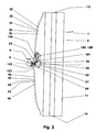
- FIG. 2 shows the plan view of a lighting unit (2), for example a tail lamp of a motor vehicle.
- the lighting unit (2) comprises a light source (6), e.g. a light emitting diode, an incandescent lamp, a halogen lamp, etc., and a light guide body (10) optically connected downstream of the light source (6).
- the light source (6) can be attached to the light guide body (10), be molded into it, be clipped, etc.
- FIG. 1 shows a dimetric view of the rear side (11) and FIG. 3 shows a side view of the light guide body (10).
- the light source (6) is seated, for example, inside the motor vehicle on the rear side (11) of the light guide body (10). From outside the motor vehicle, the lighting unit (2) has e.g. two light exit surfaces (71, 91) visible, which limit the vehicle contour. These light exit surfaces (71, 91) are arranged, for example, on the front side (12) of the light guide body (10).
- the lighting unit (2) is e.g. axisymmetric both with respect to an imaginary horizontal center longitudinal plane and with respect to an imaginary vertical center transverse plane through the light source (6). These two mentioned planes intersect in an imaginary straight line oriented in the direction of irradiation (9) through the light source (6).
- the light guide body (10) is for example a one-piece transparent plastic body, e.g. PMMA, modified PMMI, etc. It consists, for example, of a light distributor (21), an upper light output unit (61) and a lower light output unit (81). Its length is in the embodiment illustrated in Figures 1-3 - four times its depth and 2.4 times its height.
- the light distributor (21) is here a crescent-shaped component. He is in the embodiment as long as the light guide (10). Its depth is about 11% of its length, its height about 6% of its length. Symmetrically to the vertical center transverse plane lies in the rear outer surface (22) has a light entrance surface (23). This is, for example, a square planar surface whose edge length corresponds to the height of the light distributor (21).
- the outer surface (22) On both sides of the light entry surface (23), the outer surface (22) consists in each case of a stepped region (31; 41) which connects the light entry surface (23) with the respective end face (13, 14).
- the individual steps (32, 33, 42, 43) of the respective stepped area (31, 41) consist of step surfaces (32, 42) and adjoining rear side surfaces (33, 43). They are interfaces of the light distributor (21) to the environment (1).
- the step surfaces (32; 42) may also include different angles with these planes.
- a step surface (32; 42) and one of the two adjoining back face surfaces (33; 43) in the illustration of Figure 2 enclose an angle of 90 degrees with each other. This included angle can also be a sharp or an obtuse angle.
- the crest (34; 44), which is shown as a vertex in the plan view of Figure 2, is the top line of a concave notch.
- the distance between the individual vertex paths (34; 44) is not constant relative to one another.
- the distance of an arbitrary crest (34; 44) to a crest (35; 45) which is farther away from the light entry surface (23) is smaller than the distance to a crest (36; 46) which is closer to the light entry surface (36; 23).
- the distance between two adjacent vertex paths (34, 35, 34, 36, 44, 45, 44, 46) is the smaller, the farther these vertex paths (34, 35; 34, 36; 44, 45; 44, 46) are located away from the light entry surface (23).
- the light distributor (21) has a recess (25) with e.g. quadrangular cross-section symmetrical to the vertical center transverse plane.
- the length of the short diagonal of the recess (25) is e.g. 44%, the length of the long diagonal, for example, 80% of the depth of the light distributor (21).
- the distance of this recess (25) from the light entry surface (23) is for example one fifth of the depth of the light distributor (21).
- the cross-section of the recess (25) may be e.g. taper in the direction of the horizontal center longitudinal plane.
- the boundary surfaces (26, 27) of the recess (25) closer to the light entry surface (23) are, for example, sections of lateral surfaces of a cylinder, an ellipsoid, a paraboloid, a cone, etc. If the boundary surfaces (26, 27) are sections of cylinder - Or conical surfaces, the base of the cylinder or the cone may be circular, elliptical, oval, etc. The base may also be bounded by an arbitrarily curved, continuous or discontinuous space curve, e.g. through a parabola. It is also conceivable to execute these boundary surfaces (26, 27) as plane surfaces.
- the boundary surfaces (28, 29) of the recess (25), which are further away from the light entry surface (23) may be planar surfaces, portions of lateral surfaces of a cylinder, an ellipsoid, a paraboloid, a cone, etc.
- the light distributor (21) has an at least approximately V-shaped notch (51) oriented in the longitudinal direction of the light guide body (10) whose center plane coincides with the horizontal center longitudinal plane of the lighting unit (2).
- the notched surfaces (52, 53) are, for example, surface sections of a cylinder jacket, the cylinder having a base area which is circular, elliptical, oval, etc. or which is delimited by a closed, continuously or discontinuously curved space curve.
- the notched surfaces (52, 53) may also be flat surfaces or composed of individual continuous or discontinuous curved surface elements.
- the notch angle included by the two notched surfaces 52, 53 is less than 100 degrees.
- the two light output units (61, 81) are arranged symmetrically to the horizontal center longitudinal plane of the lighting unit (2). Their length corresponds in the embodiment of the length of the light guide (10), its depth is about two-thirds of the depth of the light guide (10).
- each light extraction unit (61, 81) has over its entire length a triangular longitudinal notch (63, 83) whose depth is approximately 20% of the depth of the light guide body (10).
- the apex lines (64, 84) of the longitudinal notches (63, 83) are here offset by one third of the height of the light guide body (10) offset from the horizontal center longitudinal plane.
- the notch angle of the longitudinal notches (63, 83) is for example 46 degrees.
- the boundary surfaces (65, 85) of the longitudinal notches (63, 83) remote from the horizontal center longitudinal plane are e.g. flat surfaces that are parallel to the horizontal center longitudinal plane.
- These surface elements (67, 87) are, for example, lateral surface sections of outwardly curved cylinders, cf. Figures 1 and 5. They are parallel to each other, with the imaginary cylinder axes are oriented transversely to the longitudinal direction of the light guide (10) and their length corresponds to the width of the respective boundary surface (66, 86).
- the surface elements (67, 87) may also be lateral surface sections of ellipsoids, paraboloids, etc. These can be convex or concave.
- the imaginary axes of these surface elements may also be oblique to the longitudinal direction of the light guide (10).
- the light exit surfaces (71, 91) are sections of cylinder jacket surfaces.
- the associated cylinders which are parallel to the horizontal center longitudinal plane, for example, have the length of the light guide body (10) and an oval cross-section. They are each offset by one quarter of the height of the light guide (10) to the horizontal center longitudinal plane.
- the height of the light exit surfaces (71, 91) corresponds for example to approximately one third of the height of the light guide body (10).
- optical lenses may be arranged on the light exit surfaces (71, 91).
- the light guide body (10) has an upper (62) and a lower mounting flange (82).
- These attachment flanges (62, 82) are, for example, parts of the upper (61) and lower Lichtauskoppelmaschine (81).
- the light guide body (10) is produced, for example, by injection molding. In this case, for example, at least the electrical part of a light-emitting diode (6) can be formed.
- the light guide body (10) is largely homogeneous by this manufacturing process. Individual areas of the surface of the light guide (10) can be mirrored.
- the lighting unit (2) For installation in a motor vehicle, the lighting unit (2) is fastened, for example, to the upper (62) and the lower mounting flange (82) in the vehicle body and the light source (6) is electrically connected. Optionally, located between the light exit surfaces (71, 91) is not shown here aperture.
- the installation dimensions of the lighting unit (2) in the motor vehicle are essentially determined by the dimensions of the light guide body (10).
- the installation length of the lighting unit (2) corresponds to the length of the light guide (10) and the installation height of the height of the light guide (10).
- the installation depth, cf. FIG. 2 is determined by the depth of the optical waveguide (10) and the light source (6).
- the light exit surfaces (71, 91) are visible from outside the motor vehicle. These appear as uniform, color-coordinated surfaces.
- the light (101-109) emitted by the light source (6) passes in the direction of irradiation (9) through the light entry surface (23) into the light distributor (21) of the light guide body (10).
- the light (101-109) strikes the boundary surfaces of the recess (25) formed by the boundary surfaces (26, 27).
- these interfaces are light redirecting and refracting surfaces (126, 127).
- the light (102-109) incident on the light-deflecting and refracting surfaces (126, 127) at an angle greater than the material-specific critical angle is reflected at these surfaces (126, 127).
- the two symmetrically arranged Lichtumlenkungs- and refraction surfaces (126, 127) form a light divider (125).
- the light (102-109) is deflected both into the half of the light distributor (21) shown in FIG. 2 above and into the half of the light distributor (21) shown in the same figure below.
- the reflected, diverging light (102-109) is shown simplified as a parallel light bundle (102-109).
- the two light reflectors (126, 127) of the light divider (125) are for each half of the light distributor (21) indirect light sources.
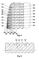
- the reflected light (102-109) is directed in the direction of the step surfaces (32, 42), cf. FIG. 4.
- FIG. 4 shows a detail of the light deflection region shown in the upper half of FIG.
- This respective section is a light deflection surface (132-139).
- These light deflection surfaces (132-139) are staggered, Of the illustrated Lichtumlenk vom (132-139), the Lichtumlenk materials (132) has the smallest distance to the light reflector (126) and the Lichtumlenk Chemistry (139) farthest from the light reflector (126) is removed.
- the light source (6) is switched on, the part (102) of the light (102-109) illuminates the light deflection surface (132), the light part (103) illuminates the light deflection surface (133), etc.
- the individual regions of the light (102-109 ) are when leaving the light reflector (126) immediately next to each other.
- the interfaces formed by the back surfaces (33, 43) are open spaces.
- the light (105) illuminating, for example, the light deflection surface (135) is reflected to the right on this light deflection surface (135) in the illustration of FIG.
- the result is a light band (105) which is wider than the adjacent light band (104).
- the light intensity, which is reflected at the Lichtumlenk preparation (135) greater than the light intensity, which is deflected at the Lichtumlenk materials (134).
- this light band (105) is narrower than that Light band (106) which is reflected at the Lichtumlenk materials (136).
- a lower light intensity is deflected at the light deflection surface (135) than at the light deflection surface (136).
- the partial luminous fluxes of the deflected light bundle are thus at least approximately the same.
- the light (107) which, when leaving the light reflector (126) in the representation of FIGS. 2 and 4, is located to the right of the light part (106), touches the light deflection surface (136) in its apex line (34) and illuminates the light deflection surface which is farthest further away (137).
- the light part (106) in turn, which illuminates the light deflection surface (136), tangents the light deflection surface (135).
- the entire reflected light (102-109) strikes the light deflection surfaces (132-139).
- the light (102-109) incident on the light diverting surfaces (132-139) has i.a. due to the absorption of the material a different light intensity.
- the more distant light deflection surfaces (132-139) are illuminated with a lower light intensity or illuminance than the closer light deflection surfaces (132-139).
- the imaginary center lines of the individual light deflection surfaces (132-139) have at least approximately the same distance from one another and, in this exemplary embodiment, are parallel to one another.
- the staggering of the Lichtumlenk vom (132-139), the distance between the individual vertex sections (34, 35, 34, 36) to each other decreases with increasing distance of the Lichtumlenk materials (132 - 139) from the light reflector (126).
- the Lichtumsch vom (132-139) can also be composed of several individual surfaces.
- the light bundle (102-109) reflected at the light deflection surfaces (132-139) is largely homogeneous, since the lower light intensity in the sections remote from the light reflector (126, 127) is compensated by a larger light deflection surface (132-139).
- the homogeneously distributed light (101-109) strikes the boundary surfaces of the light-conducting body (10) formed by the notched surfaces (52, 53).
- the two interfaces include the complementary angle of the V-shaped notch (51) at 360 degrees, e.g. at least an angle of 260 degrees. They form a deflection light divider (151) whose imaginary plane of symmetry is aligned normal to the imaginary plane of symmetry of the light divider (125).
- the deflection light distributor (151) has two reflection surfaces (152, 153), at which the incident light (101 - 109) in the illustration of Figures 1 and 3 is deflected upwards or downwards. By means of the curvature of the reflection surfaces (152, 153), the light (101-109) reflected on them can be bundled.
- these surfaces (152, 153) may have scattering optics which, for example, scatter the light (101-109) in the longitudinal direction of the light guide body (10).
- the light (101-109) reflected at the deflection light divider (151) strikes the boundary surfaces of the light guide body (10) formed by the boundary surfaces (66, 86) of the longitudinal notches (63, 83).
- the surface elements (67, 87) form segmented total reflection optics (166), which redirect the incident light (101 - 109) in the direction of the light exit surfaces (71, 91).
- the light (101-109) is fanned out, for example, by means of the semicylindrical reflection elements (167) shown in FIG. 5 in the longitudinal direction of the light guide body (10).
- the reflection elements (167) can For example, be sections of cylinder segments whose segment angle is less than 180 degrees.
- the base of the cylinders may also be limited by a parabola section, an elliptical section, etc.
- the optical axis of the reflection elements (167) shown here may also include an angle with the longitudinal axis of the light guide body (10) which is not equal to 90 degrees.
- the thus reflected and expanded light beam (102 - 109) passes through the light exit surfaces (71, 91) in the environment (1).
- the imaginary axes of the light exit surfaces (71, 91) are, for example, parallel to the imaginary plane of symmetry of the deflecting light divider (151).
- the light exit surfaces (71, 91) appear as homogeneously illuminated surfaces.
- the light exit surfaces (71, 91) can therefore be designed freely in the manufacture of the lighting unit (2) and, e.g. be adapted to the body of the motor vehicle and, for example, follow its outer contour.
- the light exit surfaces (71, 91) surfaces appear e.g. optically smooth.
- the lighting unit (2) can be constructed asymmetrically.
- the light deflection surfaces (132-139) can, for example, be illuminated directly by the light source (6).
- the lighting unit (2) may also have a plurality of light sources (6) and / or a plurality of light guide bodies (10).
- the reflection surfaces (152, 153) of the deflection light distributor (151) and / or the light deflection surfaces (130-140) can have scattering optics (166).
- the lighting unit (2) In the motor vehicle, only a small installation space is required for the lighting unit (2).
- the lighting unit (2) By arranging the light source (6) on the back (11), the lighting unit (2) can be installed laterally flush.
- a plurality of lighting units (2) can be arranged side by side and so e.g. two parallel uninterrupted long, homogeneously luminous light bands are generated.
- the arrangement of several lighting units (2) one above the other is conceivable.
- the direction of irradiation (9) is normal to an imaginary tangential plane of the two light exit surfaces (71, 91).
- the light source (6) can also be arranged so that the direction of incidence (9) with the tangential plane encloses an acute solid angle.
- the lighting unit (2) can be made in one or more parts.
Landscapes
- Engineering & Computer Science (AREA)
- Physics & Mathematics (AREA)
- General Engineering & Computer Science (AREA)
- Optics & Photonics (AREA)
- General Physics & Mathematics (AREA)
- Microelectronics & Electronic Packaging (AREA)
- Non-Portable Lighting Devices Or Systems Thereof (AREA)
- Planar Illumination Modules (AREA)
Priority Applications (1)
| Application Number | Priority Date | Filing Date | Title |
|---|---|---|---|
| SI200531104T SI1674789T1 (sl) | 2004-12-22 | 2005-11-26 | Svetilo s svetlobnim virom, svetlobnim vodnikom in svetlobnim preusmerjevalnikom |
Applications Claiming Priority (1)
| Application Number | Priority Date | Filing Date | Title |
|---|---|---|---|
| DE102004063111A DE102004063111B4 (de) | 2004-12-22 | 2004-12-22 | Leuchteinheit mit Lichtquelle, Lichtleitkörper und Lichtumlenkbereich |
Publications (3)
| Publication Number | Publication Date |
|---|---|
| EP1674789A2 true EP1674789A2 (fr) | 2006-06-28 |
| EP1674789A3 EP1674789A3 (fr) | 2008-06-25 |
| EP1674789B1 EP1674789B1 (fr) | 2010-06-23 |
Family
ID=35530839
Family Applications (1)
| Application Number | Title | Priority Date | Filing Date |
|---|---|---|---|
| EP05025844A Expired - Lifetime EP1674789B1 (fr) | 2004-12-22 | 2005-11-26 | Unité de lampe avec une source de lumière, un guide de lumière et une zone permettant de réorienter la lumière |
Country Status (6)
| Country | Link |
|---|---|
| US (1) | US7401963B2 (fr) |
| EP (1) | EP1674789B1 (fr) |
| JP (1) | JP2006179492A (fr) |
| KR (1) | KR20060071873A (fr) |
| DE (2) | DE102004063111B4 (fr) |
| SI (1) | SI1674789T1 (fr) |
Cited By (4)
| Publication number | Priority date | Publication date | Assignee | Title |
|---|---|---|---|---|
| EP1890077A1 (fr) * | 2006-08-15 | 2008-02-20 | Hella KG Hueck & Co. | Guide d'ondes pour appareil d'éclairage de véhicule |
| EP1895228A1 (fr) * | 2006-09-01 | 2008-03-05 | Valeo Vision | Dispositif d'éclairage ou de signalisation d'aspect guide de lumière haute performance pour véhicule automobile |
| CN103885116A (zh) * | 2012-12-20 | 2014-06-25 | 汽车照明罗伊特林根有限公司 | 具有带状光输出面的光导体 |
| EP2871405A3 (fr) * | 2013-11-08 | 2016-02-17 | Automotive Lighting Reutlingen GmbH | Conducteur lumineux, structure de conducteur lumineux et dispositif d'éclairage dé véhicule |
Families Citing this family (10)
| Publication number | Priority date | Publication date | Assignee | Title |
|---|---|---|---|---|
| KR101607287B1 (ko) * | 2008-11-07 | 2016-04-12 | 삼성디스플레이 주식회사 | 도광판, 이를 갖는 백라이트 어셈블리 및 표시장치 |
| US8891171B2 (en) | 2010-02-01 | 2014-11-18 | Dbm Reflex Enterprises Inc. | High sag thick lens for use in an illumination apparatus |
| US8434892B2 (en) | 2011-03-30 | 2013-05-07 | Varroccorp Holding Bv | Collimator assembly |
| EP2543540A1 (fr) | 2011-07-07 | 2013-01-09 | Odelo GmbH | Conducteur lumineux, moyen d'éclairage et éclairage de véhicule automobile |
| EP2554897A1 (fr) | 2011-08-04 | 2013-02-06 | Odelo GmbH | Conducteur lumineux, moyen d'éclairage et éclairage de véhicule automobile |
| JP6292653B2 (ja) * | 2013-07-02 | 2018-03-14 | 株式会社小糸製作所 | 車両用灯具 |
| JP2019040859A (ja) * | 2017-08-22 | 2019-03-14 | 株式会社エンプラス | 発光装置、面光源装置および光束制御部材 |
| DE102018118764A1 (de) * | 2018-08-02 | 2020-02-06 | Automotive Lighting Reutlingen Gmbh | Kraftfahrzeugbeleuchtungseinrichtung mit einem Riefen aufweisenden Lichtleiter |
| US20230167958A9 (en) * | 2020-11-17 | 2023-06-01 | Tan De Tech Co., Ltd. | Light guide structure |
| DE102023131399A1 (de) | 2023-11-13 | 2025-05-15 | Miele & Cie. Kg | Haushaltsgerät |
Citations (1)
| Publication number | Priority date | Publication date | Assignee | Title |
|---|---|---|---|---|
| EP1167869A2 (fr) | 2000-07-01 | 2002-01-02 | Hella KG Hueck & Co. | Guide de lumière |
Family Cites Families (10)
| Publication number | Priority date | Publication date | Assignee | Title |
|---|---|---|---|---|
| DE3123369A1 (de) * | 1981-06-12 | 1983-02-03 | Vdo Schindling | Lichtleiter |
| US5165772A (en) * | 1992-03-18 | 1992-11-24 | Hughes Aircraft Company | Visual display device |
| US5197792A (en) * | 1992-04-21 | 1993-03-30 | General Motors Corporation | Illuminator device for a display panel |
| DE69803297T2 (de) * | 1997-08-12 | 2002-08-22 | Breault Res Organization Inc | Doppelreflektierende linse |
| DE19804440A1 (de) * | 1998-02-05 | 1999-08-12 | Hella Kg Hueck & Co | Stabförmiger Lichtleiter |
| US6036340A (en) * | 1998-03-03 | 2000-03-14 | Ford Global Technologies, Inc. | Dimpled manifold optical element for a vehicle lighting system |
| DE69911403T2 (de) * | 1998-06-11 | 2004-06-24 | Zumtobel Staff Gmbh | Licht verteilungssystem |
| JP4162935B2 (ja) * | 2002-07-04 | 2008-10-08 | 株式会社小糸製作所 | 車両用灯具 |
| JP4153370B2 (ja) * | 2002-07-04 | 2008-09-24 | 株式会社小糸製作所 | 車両用灯具 |
| FR2853392B1 (fr) * | 2003-04-04 | 2006-06-16 | Sli Miniature Lighting Sa | Feu arriere, en particulier feu stop pour vehicule automobile |
-
2004
- 2004-12-22 DE DE102004063111A patent/DE102004063111B4/de not_active Expired - Fee Related
-
2005
- 2005-11-26 DE DE502005009789T patent/DE502005009789D1/de not_active Expired - Lifetime
- 2005-11-26 EP EP05025844A patent/EP1674789B1/fr not_active Expired - Lifetime
- 2005-11-26 SI SI200531104T patent/SI1674789T1/sl unknown
- 2005-12-12 KR KR1020050121960A patent/KR20060071873A/ko not_active Withdrawn
- 2005-12-21 JP JP2005367641A patent/JP2006179492A/ja active Pending
- 2005-12-22 US US11/315,620 patent/US7401963B2/en not_active Expired - Fee Related
Patent Citations (1)
| Publication number | Priority date | Publication date | Assignee | Title |
|---|---|---|---|---|
| EP1167869A2 (fr) | 2000-07-01 | 2002-01-02 | Hella KG Hueck & Co. | Guide de lumière |
Cited By (8)
| Publication number | Priority date | Publication date | Assignee | Title |
|---|---|---|---|---|
| EP1890077A1 (fr) * | 2006-08-15 | 2008-02-20 | Hella KG Hueck & Co. | Guide d'ondes pour appareil d'éclairage de véhicule |
| EP1895228A1 (fr) * | 2006-09-01 | 2008-03-05 | Valeo Vision | Dispositif d'éclairage ou de signalisation d'aspect guide de lumière haute performance pour véhicule automobile |
| FR2905448A1 (fr) * | 2006-09-01 | 2008-03-07 | Valeo Vision Sa | Dispositif d'eclairage ou de signalisation d'aspect guide de lumiere haute performance pour vehicule. |
| CN103885116A (zh) * | 2012-12-20 | 2014-06-25 | 汽车照明罗伊特林根有限公司 | 具有带状光输出面的光导体 |
| EP2784379A1 (fr) * | 2012-12-20 | 2014-10-01 | Automotive Lighting Reutlingen GmbH | Conducteur lumineux doté d'une surface de sortie de lumière en forme de bande |
| US9528682B2 (en) | 2012-12-20 | 2016-12-27 | Automotive Lighting Reutlingen Gmbh | Light conductor with a ribbon-shaped light emitting area |
| CN103885116B (zh) * | 2012-12-20 | 2018-06-12 | 汽车照明罗伊特林根有限公司 | 具有带状光输出面的光导体 |
| EP2871405A3 (fr) * | 2013-11-08 | 2016-02-17 | Automotive Lighting Reutlingen GmbH | Conducteur lumineux, structure de conducteur lumineux et dispositif d'éclairage dé véhicule |
Also Published As
| Publication number | Publication date |
|---|---|
| EP1674789B1 (fr) | 2010-06-23 |
| DE102004063111A1 (de) | 2006-07-06 |
| EP1674789A3 (fr) | 2008-06-25 |
| JP2006179492A (ja) | 2006-07-06 |
| US20060164855A1 (en) | 2006-07-27 |
| DE102004063111B4 (de) | 2011-04-28 |
| DE502005009789D1 (de) | 2010-08-05 |
| US7401963B2 (en) | 2008-07-22 |
| SI1674789T1 (sl) | 2010-10-29 |
| KR20060071873A (ko) | 2006-06-27 |
Similar Documents
| Publication | Publication Date | Title |
|---|---|---|
| EP2607774B1 (fr) | Dispositif d'éclairage d'un véhicule automobile avec une surface lumineuse longue et plane | |
| EP1684002B1 (fr) | Unité d' éclairage avec distributeur de lumière | |
| EP1674789B1 (fr) | Unité de lampe avec une source de lumière, un guide de lumière et une zone permettant de réorienter la lumière | |
| EP2688769B1 (fr) | Lampe pour véhicule destinée à éclairer l'habitacle du véhicule | |
| EP2871405B1 (fr) | Conducteur lumineux, structure de conducteur lumineux et dispositif d'éclairage de véhicule | |
| EP2889529A2 (fr) | Éclairage de véhicule automobile doté d'une apparence extensive ou linéaire | |
| DE102017114476B4 (de) | Beleuchtungseinrichtung eines Kraftfahrzeugs | |
| DE102022113052A1 (de) | Beleuchtungsvorrichtung für ein Kraftfahrzeug | |
| EP2317212A1 (fr) | Dispositif d'éclairage pour un véhicule automobile | |
| EP3210827A1 (fr) | Feu de véhicule | |
| EP2963334B1 (fr) | Système de conducteurs lumineux utilisé dans un dispositif d'éclairage d'un véhicule automobile et dispositif d'éclairage de véhicule automobile doté d'un tel système de conducteurs lumineux | |
| WO2020104311A1 (fr) | Dispositif d'éclairage pour véhicules | |
| DE102007023076A1 (de) | Beleuchtungseinrichtung für Kraftfahrzeuge | |
| DE102017105838A1 (de) | Beleuchtungseinrichtung eines Kraftfahrzeugs mit einer Lichtleiteranordnung | |
| EP3531012A1 (fr) | Dispositif d'éclairage pour véhicules automobiles pourvu de guide de lumière allongé | |
| DE19857561A1 (de) | Leuchte, insbesondere für Kraftfahrzeuge | |
| DE10022779A1 (de) | Stabförmiger Lichtleiter | |
| DE102014206593A1 (de) | Kraftfahrzeugleuchte mit Wischeffekt | |
| EP3812653B1 (fr) | Feu de signalisation pourvu de guide de lumière | |
| DE102015207960A1 (de) | Plattenförmiges Lichtleiterelement zum Einsatz in einer Beleuchtungseinrichtung eines Kraftfahrzeugs und Beleuchtungseinrichtung mit einem solchen Lichtleiterelement | |
| DE102017106441A1 (de) | Kraftfahrzeugleuchte mit einem flächigen Lichtleiter | |
| DE102017119475A1 (de) | Lichtleiter | |
| DE19850443A1 (de) | Leuchte, insbesondere für Kraftfahrzeuge | |
| DE102017125212B4 (de) | Linse und leuchtmodul | |
| DE102015218134A1 (de) | Leuchten-Lichtmodul für ein Kraftfahrzeug |
Legal Events
| Date | Code | Title | Description |
|---|---|---|---|
| PUAI | Public reference made under article 153(3) epc to a published international application that has entered the european phase |
Free format text: ORIGINAL CODE: 0009012 |
|
| AK | Designated contracting states |
Kind code of ref document: A2 Designated state(s): AT BE BG CH CY CZ DE DK EE ES FI FR GB GR HU IE IS IT LI LT LU LV MC NL PL PT RO SE SI SK TR |
|
| AX | Request for extension of the european patent |
Extension state: AL BA HR MK YU |
|
| PUAL | Search report despatched |
Free format text: ORIGINAL CODE: 0009013 |
|
| AK | Designated contracting states |
Kind code of ref document: A3 Designated state(s): AT BE BG CH CY CZ DE DK EE ES FI FR GB GR HU IE IS IT LI LT LU LV MC NL PL PT RO SE SI SK TR |
|
| AX | Request for extension of the european patent |
Extension state: AL BA HR MK YU |
|
| 17P | Request for examination filed |
Effective date: 20081222 |
|
| AKX | Designation fees paid |
Designated state(s): DE FR IT SI |
|
| RAP1 | Party data changed (applicant data changed or rights of an application transferred) |
Owner name: ODELO GMBH |
|
| GRAP | Despatch of communication of intention to grant a patent |
Free format text: ORIGINAL CODE: EPIDOSNIGR1 |
|
| RIN1 | Information on inventor provided before grant (corrected) |
Inventor name: MUELLER, OTTO Inventor name: ERBER, ANDREAS Inventor name: STEFANOV, EMIL |
|
| RAP1 | Party data changed (applicant data changed or rights of an application transferred) |
Owner name: ODELO GMBH |
|
| GRAS | Grant fee paid |
Free format text: ORIGINAL CODE: EPIDOSNIGR3 |
|
| GRAA | (expected) grant |
Free format text: ORIGINAL CODE: 0009210 |
|
| AK | Designated contracting states |
Kind code of ref document: B1 Designated state(s): DE FR IT SI |
|
| REF | Corresponds to: |
Ref document number: 502005009789 Country of ref document: DE Date of ref document: 20100805 Kind code of ref document: P |
|
| PLBE | No opposition filed within time limit |
Free format text: ORIGINAL CODE: 0009261 |
|
| STAA | Information on the status of an ep patent application or granted ep patent |
Free format text: STATUS: NO OPPOSITION FILED WITHIN TIME LIMIT |
|
| 26N | No opposition filed |
Effective date: 20110324 |
|
| REG | Reference to a national code |
Ref country code: DE Ref legal event code: R097 Ref document number: 502005009789 Country of ref document: DE Effective date: 20110323 |
|
| PGFP | Annual fee paid to national office [announced via postgrant information from national office to epo] |
Ref country code: FR Payment date: 20121130 Year of fee payment: 8 |
|
| PGFP | Annual fee paid to national office [announced via postgrant information from national office to epo] |
Ref country code: IT Payment date: 20121122 Year of fee payment: 8 |
|
| REG | Reference to a national code |
Ref country code: DE Ref legal event code: R082 Ref document number: 502005009789 Country of ref document: DE Representative=s name: RPK PATENTANWAELTE REINHARDT, POHLMANN UND KAU, DE |
|
| PGFP | Annual fee paid to national office [announced via postgrant information from national office to epo] |
Ref country code: SI Payment date: 20131030 Year of fee payment: 9 |
|
| REG | Reference to a national code |
Ref country code: FR Ref legal event code: ST Effective date: 20140731 |
|
| PG25 | Lapsed in a contracting state [announced via postgrant information from national office to epo] |
Ref country code: IT Free format text: LAPSE BECAUSE OF NON-PAYMENT OF DUE FEES Effective date: 20131126 |
|
| REG | Reference to a national code |
Ref country code: DE Ref legal event code: R082 Ref document number: 502005009789 Country of ref document: DE Representative=s name: RPK PATENTANWAELTE REINHARDT, POHLMANN UND KAU, DE |
|
| PG25 | Lapsed in a contracting state [announced via postgrant information from national office to epo] |
Ref country code: FR Free format text: LAPSE BECAUSE OF NON-PAYMENT OF DUE FEES Effective date: 20131202 |
|
| PG25 | Lapsed in a contracting state [announced via postgrant information from national office to epo] |
Ref country code: SI Free format text: LAPSE BECAUSE OF NON-PAYMENT OF DUE FEES Effective date: 20141127 |
|
| REG | Reference to a national code |
Ref country code: SI Ref legal event code: KO00 Effective date: 20150718 |
|
| REG | Reference to a national code |
Ref country code: DE Ref legal event code: R079 Ref document number: 502005009789 Country of ref document: DE Free format text: PREVIOUS MAIN CLASS: F21S0008100000 Ipc: F21S0043000000 |
|
| PGFP | Annual fee paid to national office [announced via postgrant information from national office to epo] |
Ref country code: DE Payment date: 20201119 Year of fee payment: 16 |
|
| REG | Reference to a national code |
Ref country code: DE Ref legal event code: R119 Ref document number: 502005009789 Country of ref document: DE |
|
| PG25 | Lapsed in a contracting state [announced via postgrant information from national office to epo] |
Ref country code: DE Free format text: LAPSE BECAUSE OF NON-PAYMENT OF DUE FEES Effective date: 20220601 |