EP1676063B1 - Überfüllungsschutzvorrichtung - Google Patents
Überfüllungsschutzvorrichtung Download PDFInfo
- Publication number
- EP1676063B1 EP1676063B1 EP20040793667 EP04793667A EP1676063B1 EP 1676063 B1 EP1676063 B1 EP 1676063B1 EP 20040793667 EP20040793667 EP 20040793667 EP 04793667 A EP04793667 A EP 04793667A EP 1676063 B1 EP1676063 B1 EP 1676063B1
- Authority
- EP
- European Patent Office
- Prior art keywords
- protection device
- overfill protection
- valve body
- float
- auxiliary
- Prior art date
- Legal status (The legal status is an assumption and is not a legal conclusion. Google has not performed a legal analysis and makes no representation as to the accuracy of the status listed.)
- Expired - Lifetime
Links
- 239000012528 membrane Substances 0.000 claims abstract description 12
- 239000000446 fuel Substances 0.000 claims description 7
- 238000009434 installation Methods 0.000 claims description 6
- 238000002347 injection Methods 0.000 claims description 2
- 239000007924 injection Substances 0.000 claims description 2
- 239000007788 liquid Substances 0.000 abstract description 7
- 239000012530 fluid Substances 0.000 description 10
- ATUOYWHBWRKTHZ-UHFFFAOYSA-N Propane Chemical compound CCC ATUOYWHBWRKTHZ-UHFFFAOYSA-N 0.000 description 4
- 238000010276 construction Methods 0.000 description 4
- 239000007789 gas Substances 0.000 description 3
- 239000000203 mixture Substances 0.000 description 2
- 239000001294 propane Substances 0.000 description 2
- 238000011144 upstream manufacturing Methods 0.000 description 2
- 239000001273 butane Substances 0.000 description 1
- 238000002485 combustion reaction Methods 0.000 description 1
- 230000006835 compression Effects 0.000 description 1
- 238000007906 compression Methods 0.000 description 1
- 230000001419 dependent effect Effects 0.000 description 1
- 230000000694 effects Effects 0.000 description 1
- 230000005484 gravity Effects 0.000 description 1
- 238000005259 measurement Methods 0.000 description 1
- IJDNQMDRQITEOD-UHFFFAOYSA-N n-butane Chemical compound CCCC IJDNQMDRQITEOD-UHFFFAOYSA-N 0.000 description 1
- OFBQJSOFQDEBGM-UHFFFAOYSA-N n-pentane Natural products CCCCC OFBQJSOFQDEBGM-UHFFFAOYSA-N 0.000 description 1
Images

Classifications
-
- F—MECHANICAL ENGINEERING; LIGHTING; HEATING; WEAPONS; BLASTING
- F16—ENGINEERING ELEMENTS AND UNITS; GENERAL MEASURES FOR PRODUCING AND MAINTAINING EFFECTIVE FUNCTIONING OF MACHINES OR INSTALLATIONS; THERMAL INSULATION IN GENERAL
- F16K—VALVES; TAPS; COCKS; ACTUATING-FLOATS; DEVICES FOR VENTING OR AERATING
- F16K1/00—Lift valves or globe valves, i.e. cut-off apparatus with closure members having at least a component of their opening and closing motion perpendicular to the closing faces
- F16K1/30—Lift valves or globe valves, i.e. cut-off apparatus with closure members having at least a component of their opening and closing motion perpendicular to the closing faces specially adapted for pressure containers
-
- F—MECHANICAL ENGINEERING; LIGHTING; HEATING; WEAPONS; BLASTING
- F16—ENGINEERING ELEMENTS AND UNITS; GENERAL MEASURES FOR PRODUCING AND MAINTAINING EFFECTIVE FUNCTIONING OF MACHINES OR INSTALLATIONS; THERMAL INSULATION IN GENERAL
- F16K—VALVES; TAPS; COCKS; ACTUATING-FLOATS; DEVICES FOR VENTING OR AERATING
- F16K1/00—Lift valves or globe valves, i.e. cut-off apparatus with closure members having at least a component of their opening and closing motion perpendicular to the closing faces
- F16K1/30—Lift valves or globe valves, i.e. cut-off apparatus with closure members having at least a component of their opening and closing motion perpendicular to the closing faces specially adapted for pressure containers
- F16K1/304—Shut-off valves with additional means
- F16K1/305—Shut-off valves with additional means with valve member and actuator on the same side of the seat
-
- F—MECHANICAL ENGINEERING; LIGHTING; HEATING; WEAPONS; BLASTING
- F16—ENGINEERING ELEMENTS AND UNITS; GENERAL MEASURES FOR PRODUCING AND MAINTAINING EFFECTIVE FUNCTIONING OF MACHINES OR INSTALLATIONS; THERMAL INSULATION IN GENERAL
- F16K—VALVES; TAPS; COCKS; ACTUATING-FLOATS; DEVICES FOR VENTING OR AERATING
- F16K1/00—Lift valves or globe valves, i.e. cut-off apparatus with closure members having at least a component of their opening and closing motion perpendicular to the closing faces
- F16K1/30—Lift valves or globe valves, i.e. cut-off apparatus with closure members having at least a component of their opening and closing motion perpendicular to the closing faces specially adapted for pressure containers
- F16K1/304—Shut-off valves with additional means
- F16K1/306—Shut-off valves with additional means with a valve member, e.g. stem or shaft, passing through the seat
-
- F—MECHANICAL ENGINEERING; LIGHTING; HEATING; WEAPONS; BLASTING
- F16—ENGINEERING ELEMENTS AND UNITS; GENERAL MEASURES FOR PRODUCING AND MAINTAINING EFFECTIVE FUNCTIONING OF MACHINES OR INSTALLATIONS; THERMAL INSULATION IN GENERAL
- F16K—VALVES; TAPS; COCKS; ACTUATING-FLOATS; DEVICES FOR VENTING OR AERATING
- F16K1/00—Lift valves or globe valves, i.e. cut-off apparatus with closure members having at least a component of their opening and closing motion perpendicular to the closing faces
- F16K1/30—Lift valves or globe valves, i.e. cut-off apparatus with closure members having at least a component of their opening and closing motion perpendicular to the closing faces specially adapted for pressure containers
- F16K1/307—Additional means used in combination with the main valve
-
- F—MECHANICAL ENGINEERING; LIGHTING; HEATING; WEAPONS; BLASTING
- F16—ENGINEERING ELEMENTS AND UNITS; GENERAL MEASURES FOR PRODUCING AND MAINTAINING EFFECTIVE FUNCTIONING OF MACHINES OR INSTALLATIONS; THERMAL INSULATION IN GENERAL
- F16K—VALVES; TAPS; COCKS; ACTUATING-FLOATS; DEVICES FOR VENTING OR AERATING
- F16K31/00—Actuating devices; Operating means; Releasing devices
- F16K31/12—Actuating devices; Operating means; Releasing devices actuated by fluid
- F16K31/18—Actuating devices; Operating means; Releasing devices actuated by fluid actuated by a float
-
- F—MECHANICAL ENGINEERING; LIGHTING; HEATING; WEAPONS; BLASTING
- F16—ENGINEERING ELEMENTS AND UNITS; GENERAL MEASURES FOR PRODUCING AND MAINTAINING EFFECTIVE FUNCTIONING OF MACHINES OR INSTALLATIONS; THERMAL INSULATION IN GENERAL
- F16K—VALVES; TAPS; COCKS; ACTUATING-FLOATS; DEVICES FOR VENTING OR AERATING
- F16K31/00—Actuating devices; Operating means; Releasing devices
- F16K31/12—Actuating devices; Operating means; Releasing devices actuated by fluid
- F16K31/18—Actuating devices; Operating means; Releasing devices actuated by fluid actuated by a float
- F16K31/34—Actuating devices; Operating means; Releasing devices actuated by fluid actuated by a float acting on pilot valve controlling the cut-off apparatus
-
- F—MECHANICAL ENGINEERING; LIGHTING; HEATING; WEAPONS; BLASTING
- F16—ENGINEERING ELEMENTS AND UNITS; GENERAL MEASURES FOR PRODUCING AND MAINTAINING EFFECTIVE FUNCTIONING OF MACHINES OR INSTALLATIONS; THERMAL INSULATION IN GENERAL
- F16K—VALVES; TAPS; COCKS; ACTUATING-FLOATS; DEVICES FOR VENTING OR AERATING
- F16K31/00—Actuating devices; Operating means; Releasing devices
- F16K31/12—Actuating devices; Operating means; Releasing devices actuated by fluid
- F16K31/36—Actuating devices; Operating means; Releasing devices actuated by fluid in which fluid from the circuit is constantly supplied to the fluid motor
- F16K31/38—Actuating devices; Operating means; Releasing devices actuated by fluid in which fluid from the circuit is constantly supplied to the fluid motor in which the fluid works directly on both sides of the fluid motor, one side being connected by means of a restricted passage and the motor being actuated by operating a discharge from that side
- F16K31/385—Actuating devices; Operating means; Releasing devices actuated by fluid in which fluid from the circuit is constantly supplied to the fluid motor in which the fluid works directly on both sides of the fluid motor, one side being connected by means of a restricted passage and the motor being actuated by operating a discharge from that side the fluid acting on a diaphragm
-
- F—MECHANICAL ENGINEERING; LIGHTING; HEATING; WEAPONS; BLASTING
- F17—STORING OR DISTRIBUTING GASES OR LIQUIDS
- F17C—VESSELS FOR CONTAINING OR STORING COMPRESSED, LIQUEFIED OR SOLIDIFIED GASES; FIXED-CAPACITY GAS-HOLDERS; FILLING VESSELS WITH, OR DISCHARGING FROM VESSELS, COMPRESSED, LIQUEFIED, OR SOLIDIFIED GASES
- F17C2250/00—Accessories; Control means; Indicating, measuring or monitoring of parameters
- F17C2250/04—Indicating or measuring of parameters as input values
- F17C2250/0404—Parameters indicated or measured
- F17C2250/0408—Level of content in the vessel
- F17C2250/0413—Level of content in the vessel with floats
Definitions
- the present invention relates to an overfill protection device comprising a filling channel with inlet and main outlet, wherein a main valve is fitted between them, wherein the inlet pressure acts on one side of the main valve body thereof, as well as an auxiliary valve, connected on one side via a restriction to the filling channel and connected on the other side to an auxiliary outlet, wherein the pressure that acts downstream of said restriction is the pressure that acts on the other side of said main valve body, wherein the valve body of said auxiliary valve is connected to a float device such that the auxiliary outlet is shut off when the desired fill level is reached and wherein said main valve is constructed such that this closes the main outlet when the pressure exerted on either side of the main valve body is the same.
- Such an overfill protection device is used in particular in LPG installations and other constructions where overfilling of a tank, vessel or the like with liquid has to be prevented automatically. In this context it is desirable that a reproducible result for the closure of the overfill protection device is obtained.
- the auxiliary valve body is above a recessed part in the cam plate, that is to say is no longer forcibly opened by the cam plate.
- the auxiliary valve body is automatically pushed away and closed by the fluid flowing through the auxiliary outlet.
- the pressure upstream of the auxiliary valve body is the pressure that acts on one side of the main valve.
- the fill pressure acts on the other side of the main valve. If this pressure becomes equal, the main valve will close by means of the spring. That is to say, the main valve is also closed by the closing movement of the auxiliary valve.
- the construction in the state of the art is made such that under the most common conditions it can be guaranteed that closing takes place.
- the aim of the present invention is to provide an overfill protection device that functions accurately and reproducibly. That is to say, it must always be guaranteed that shutting off of the auxiliary valve, and thus shutting off of the main valve, takes place only after the desired fill level is reached, but also not later than this.
- This aim is realised with an overfill protection device having the features of claim 1.
- This rod is preferably a pull rod and the force is preferably traction.
- closure of the auxiliary valve body is not left to the flow of the fluid through the auxiliary outlet but the various aspects are under enforced control by applying a (pull) force to the auxiliary valve body.
- This (pull) force is generated by the float device. Accurate closure can thus be guaranteed under all circumstances.
- auxiliary valve can now be of completely different construction, it is also possible to determine the moment at which the auxiliary valve closes very accurately with the aid of lever relationships. That is to say, on the one hand it is possible to guarantee closure under all circumstances when a specific fill level is reached but, on the other hand, it is always guaranteed that an optimum large quantity of fluid can be introduced.
- the float device pivot (part) of the float device is provided with an auxiliary arm that is connected to the pull rod.
- This auxiliary arm can be part of the pivot disc of the float device.
- the main valve body can be constructed in any way known in the art. Particularly sensitive response can be achieved if this is constructed as a membrane. Moreover, this membrane or any other construction of the main valve body can be provided with the restriction.
- the float device arm can be expended beyond the pivot on the side opposite the float and provided with a counterweight for more accurate response of the float device and to reinforce the traction to be applied. This is important in particular if the overfill protection device is used in combination with liquids that have a relatively low relative density, such as propane, butane and mixtures thereof.
- a non-return valve is preferably fitted in the filling channel. Moreover, the non-return valve is fitted together with the overfill protection device and other components on a bearer plate that can be fitted as a whole on a pressure vessel. Such further components are fuel pumps, pressure relief safety devices, level indicators and the like.
- the invention can be used in particular in an LPG installation for a vehicle comprising a storage tank and a fuel injection system for the internal combustion engine of said vehicle.
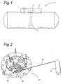
- a tank of, for example, an LPG installation for a motor vehicle is shown by 1. It must be understood that the invention is not restricted to this. Other examples of applications are stationary storage tanks.
- the invention can be used where it has to be guaranteed that when filling with some liquid the supply of liquid has to be automatically cut off if a specific liquid level is reached. That is to say, it is also not necessary that the tank is a pressurised tank.
- a so-called accessory housing which accommodates the accessory plate 3, is indicated by 2.
- a housing is provided with a relief line (not shown), where should leaks arise undesirable entry of gases into a compartment is prevented.
- Such an accessory housing is typical for motor vehicles and can be omitted in other applications.
- Various components are mounted on the accessory plate, of which components a fuel pump is indicated by 4. Further components can be a level measurement control, pressure relief safety device, relief line and the like.
- the fill line and the overfill protection device arranged therein that are important. This is indicated in its entirety by 5 in Fig. 3 . This consists of an inlet 6, through which the fluid to be introduced has to be introduced.
- a main valve 10 adjoins inlet channel 7 downstream of the non-return valve 8.
- This main valve 10 consists of a main valve body or membrane 11 and a seat interacting therewith. This seat opens into a main outlet 9. In the position shown the main outlet 9 has been closed by the membrane 11 having moved up.
- Membrane 11 is provided with a restriction or opening 12.
- the membrane 11 is bordered on one side by a first chamber 14 and on the other side by a second chamber 15.
- a compression spring 16 which drives the membrane with a small bias into the closed position, is fitted in the second chamber 15.
- Second chamber 15 is connected via restriction or opening 12 to the filling channel 7.
- second chamber 15 is provided with an auxiliary valve 18.
- This consists of a seat 19 connected to an auxiliary outlet 28 and, on the other side, an auxiliary valve body 20.
- This auxiliary valve body can be moved back and forth over the distance a indicated by arrow 30 by driving with a pull rod 21.
- Pull rod 21 is attached at 27 to a disc or arm 29 fitted close to pivot 26 of float device 22.
- Float device 22 also has a float 23 and a counterweight 25 arranged on the opposite side thereto (see Fig. 2 ).
- the device described above functions as follows.
- the membrane When the tank 1 is empty and when fluid enters through inlet channel 7 and the non-return valve 8 opens, the membrane will move downwards, starting from the position in Fig. 3 , against the pressure of spring 16. Only a small fraction of the fluid will move through opening or restriction 12 to the second chamber and will be discharged from there without hindrance via auxiliary outlet 28 when auxiliary valve 18 is open.
- auxiliary valve 18 As a result of the overpressure of the fluid introduced this situation is stable, that is to say membrane 11 will be continuously pressed down.
- the float 23 of the float device 22 will move upwards as the level in tank 1 rises. As a result a traction will be exerted on pull rod 21, that is to say the auxiliary valve body 20 will move to the right.
Landscapes
- Engineering & Computer Science (AREA)
- General Engineering & Computer Science (AREA)
- Mechanical Engineering (AREA)
- Filling Or Discharging Of Gas Storage Vessels (AREA)
- Measuring Volume Flow (AREA)
- Float Valves (AREA)
- Safety Valves (AREA)
Claims (11)
- Überfüllschutzvorrichtung (1), enthaltend ein Gehäuse, das einen Befüllungskanal (7) mit einem Einlass (6) und einem Hauptauslass (9) hat, wobei ein Hauptventil (10) zwischen beiden eingefügt ist und ein Einlassdruck auf eine Seite (14) des Hauptventilkörpers wirkt, wie auch ein Zusatzventil (18), das auf einer Seite über eine Einschnürung (12) mit dem Befüllungskanal (7) verbunden ist und auf der anderen Seite mit einem Zusatzauslass (28) verbunden ist, wobei der Druck, der stromabwärtig von dieser Einschnürung (12) wirkt, der Druck ist, der auf die andere Seite (15) des Hauptventilkörpers wirkt, wobei der Ventilkörper (20) des Zusatzventils dauerhaft mit einer Schwimmervorrichtung (22) derart verbunden ist, dass der Zusatzauslass (28) abgesperrt wird, wenn der gewünschte Füllstand erreicht ist, und das Hauptventil derart aufgebaut ist, dass es den Hauptauslass verschließt, wenn der Druck, der auf jeder Seite des Hauptventilkörpers wirkt, derselbe ist, wobei die Schwimmervorrichtung einen Schwimmer (23) und einen Arm (24) enthält, der mit dem Schwimmer (23) verbunden ist, wobei der Arm (24) mit dem Gehäuse durch einen Zapfen (26) verbunden ist, dadurch gekennzeichnet, dass der Zusatzventilkörper mit der Schwimmervorrichtung über einen Stab (21) verbunden ist, der mit einer Scheibe oder einem Arm (29) in der Nähe des Zapfens (26) der Schwimmervorrichtung (22) derart verbunden ist, dass eine Kraft, die das Zusatzventil schließt, von der Schwimmervorrichtung auf den Stab ausgeübt wird, wenn sich die Schwimmervorrichtung anhebt.
- Überfüllschutzvorrichtung nach Anspruch 1, bei der der Zapfen der Schwimmervorrichtung einen Zusatzarm (29) hat, der mit dem Stab verbunden ist.
- Überfüllschutzvorrichtung nach Anspruch 1 oder 2, bei der der Stab (21) ein Zugstab ist.
- Überfüllschutzvorrichtung nach einem der vorhergehenden Ansprüche, bei der die Schwimmervorrichtung mit einem Gegengewicht (25) versehen ist.
- Überfüllschutzvorrichtung nach einem der vorhergehenden Ansprüche, bei der die Einschnürung (12) in dem Hauptventilkörper ausgebildet ist.
- Überfüllschutzvorrichtung nach einem der vorhergehenden Ansprüche, bei der sich der Zusatzventilkörper um eine Distanz (a) von mehr als 15 mm zwischen seiner vollständig geöffneten und seiner vollständig geschlossenen Stellung bewegt.
- Überfüllschutzvorrichtung nach einem der vorhergehenden Ansprüche, bei der ein Rückschlagventil (8) in der Nähe des Einlasses (6) in dem Befüllungskanal (7) eingefügt ist.
- Überfüllschutzvorrichtung nach einem der vorhergehenden Ansprüche, die auf einer Trägerplatte (3) montiert ist.
- Überfüllschutzvorrichtung nach Anspruch 8, bei der die Trägerplatte eine Befestigungseinrichtung für eine Brennstoffpumpe und eine Druckablass-Sicherheitsvorrichtung hat.
- Überfüllschutzvorrichtung nach einem der vorhergehenden Ansprüche, bei der der Hauptventilkörper eine Membran (11) enthält.
- LPG-Installation für ein Fahrzeug, enthaltend einen Speichertank und ein Brennstoffeinspritzsystem, wobei der Speichertank über eine Überfüllschutzvorrichtung (5) nach einem der Ansprüche 1 bis 9 verfügt.
Priority Applications (1)
| Application Number | Priority Date | Filing Date | Title |
|---|---|---|---|
| PL04793667T PL1676063T3 (pl) | 2003-10-20 | 2004-10-20 | Urządzenie zabezpieczające przed przepełnieniem |
Applications Claiming Priority (2)
| Application Number | Priority Date | Filing Date | Title |
|---|---|---|---|
| NL1024572A NL1024572C2 (nl) | 2003-10-20 | 2003-10-20 | Overvulbeveiliging. |
| PCT/NL2004/000742 WO2005038313A1 (en) | 2003-10-20 | 2004-10-20 | Overfill protection device |
Publications (2)
| Publication Number | Publication Date |
|---|---|
| EP1676063A1 EP1676063A1 (de) | 2006-07-05 |
| EP1676063B1 true EP1676063B1 (de) | 2011-10-12 |
Family
ID=34464916
Family Applications (1)
| Application Number | Title | Priority Date | Filing Date |
|---|---|---|---|
| EP20040793667 Expired - Lifetime EP1676063B1 (de) | 2003-10-20 | 2004-10-20 | Überfüllungsschutzvorrichtung |
Country Status (8)
| Country | Link |
|---|---|
| EP (1) | EP1676063B1 (de) |
| KR (1) | KR101297934B1 (de) |
| CN (1) | CN100424390C (de) |
| AT (1) | ATE528560T1 (de) |
| AU (1) | AU2004281343B2 (de) |
| NL (1) | NL1024572C2 (de) |
| PL (1) | PL1676063T3 (de) |
| WO (1) | WO2005038313A1 (de) |
Cited By (2)
| Publication number | Priority date | Publication date | Assignee | Title |
|---|---|---|---|---|
| US9187307B2 (en) | 2014-04-09 | 2015-11-17 | Fox Environmental Products, Llc | Fuel surge arrestor |
| US9233823B2 (en) | 2014-04-09 | 2016-01-12 | Fox Environmental Products, Llc | Fuel surge arrestor |
Families Citing this family (3)
| Publication number | Priority date | Publication date | Assignee | Title |
|---|---|---|---|---|
| CN101348229B (zh) * | 2008-09-02 | 2011-09-28 | 张连生 | 带有防溢系统的鹤管 |
| GB0915124D0 (en) * | 2009-09-01 | 2009-10-07 | Hillriver Ltd | Fuel level sensing device |
| KR101303560B1 (ko) * | 2011-11-17 | 2013-09-09 | 기아자동차주식회사 | 차량용 엘피지 봄베의 압력유지시스템 |
Family Cites Families (5)
| Publication number | Priority date | Publication date | Assignee | Title |
|---|---|---|---|---|
| US2731030A (en) * | 1954-08-31 | 1956-01-17 | Petroleum Systems Inc | Overflow float valves |
| US6138709A (en) * | 1998-01-27 | 2000-10-31 | Home; William | Overfill protection device |
| FR2778397B1 (fr) * | 1998-05-07 | 2000-06-09 | Clesse Ind | Dispositif de remplissage pour reservoir de gaz de petrole liquefie |
| US6408869B1 (en) * | 2000-08-07 | 2002-06-25 | Gaap Gas Control Inc. | Safety valve |
| CN2467853Y (zh) * | 2001-02-06 | 2001-12-26 | 上海太设环保设备有限公司 | 车用石油液化气钢瓶组合阀限量输入装置 |
-
2003
- 2003-10-20 NL NL1024572A patent/NL1024572C2/nl not_active IP Right Cessation
-
2004
- 2004-10-20 AU AU2004281343A patent/AU2004281343B2/en not_active Ceased
- 2004-10-20 AT AT04793667T patent/ATE528560T1/de not_active IP Right Cessation
- 2004-10-20 PL PL04793667T patent/PL1676063T3/pl unknown
- 2004-10-20 KR KR1020067009491A patent/KR101297934B1/ko not_active Expired - Fee Related
- 2004-10-20 CN CNB2004800307423A patent/CN100424390C/zh not_active Expired - Fee Related
- 2004-10-20 EP EP20040793667 patent/EP1676063B1/de not_active Expired - Lifetime
- 2004-10-20 WO PCT/NL2004/000742 patent/WO2005038313A1/en not_active Ceased
Cited By (2)
| Publication number | Priority date | Publication date | Assignee | Title |
|---|---|---|---|---|
| US9187307B2 (en) | 2014-04-09 | 2015-11-17 | Fox Environmental Products, Llc | Fuel surge arrestor |
| US9233823B2 (en) | 2014-04-09 | 2016-01-12 | Fox Environmental Products, Llc | Fuel surge arrestor |
Also Published As
| Publication number | Publication date |
|---|---|
| EP1676063A1 (de) | 2006-07-05 |
| PL1676063T3 (pl) | 2012-03-30 |
| CN1871468A (zh) | 2006-11-29 |
| AU2004281343B2 (en) | 2010-04-29 |
| KR101297934B1 (ko) | 2013-08-19 |
| AU2004281343A1 (en) | 2005-04-28 |
| CN100424390C (zh) | 2008-10-08 |
| WO2005038313A1 (en) | 2005-04-28 |
| ATE528560T1 (de) | 2011-10-15 |
| KR20060097030A (ko) | 2006-09-13 |
| NL1024572C2 (nl) | 2005-04-27 |
Similar Documents
| Publication | Publication Date | Title |
|---|---|---|
| KR101302414B1 (ko) | 기계식 작동 차단 밸브, 차단 밸브, 연료 탱크 배출 제어 시스템, 가솔린 엔진 차량 및 차단 방법 | |
| KR100490478B1 (ko) | 연료증기회수를위한제어밸브및시스템 | |
| US6951209B2 (en) | Fuel vapor processing system | |
| US5813432A (en) | Automatic shut-off valve arrangement | |
| US5782262A (en) | Gas ventilation apparatus for a fuel tank | |
| US6003547A (en) | Valve and filling arrangement | |
| US7296600B2 (en) | Valve assembly and refueling sensor | |
| KR19980702018A (ko) | 증발가스회수 연료탱크시스템 | |
| US6408869B1 (en) | Safety valve | |
| US4903672A (en) | Fuel tank overfill prevention | |
| US7055556B2 (en) | Controlling vapor recirculation during refueling of a tank through a filler tube from a dispensing nozzle | |
| JP2000203700A (ja) | 液体貯蔵タンク用充填リミッタ | |
| US20080173084A1 (en) | Method and device for continuous measuring of dynamic fluid consumption, including pressure regulator | |
| AU2004281343B2 (en) | Overfill protection device | |
| US4809740A (en) | Excess flow limiter | |
| CN1071647C (zh) | 机动车燃料箱的排气阀 | |
| US4405000A (en) | Automatic shutoff valve | |
| CN1189341C (zh) | 特别是用于加油排气管道的安全阀 | |
| KR920005736Y1 (ko) | 자동차용 lpg탱크의 과충진 방지용 밸브장치 | |
| KR200142102Y1 (ko) | 연료탱크의 밸브장치 | |
| KR102463411B1 (ko) | 자동차 연료시스템의 오버플로우 방지 장치 | |
| JPH08197968A (ja) | 車両用燃料貯留装置 | |
| KR200318894Y1 (ko) | 가스 과충전 방지밸브 | |
| JP3138402B2 (ja) | 液体燃料注入装置 | |
| JPH0511439Y2 (de) |
Legal Events
| Date | Code | Title | Description |
|---|---|---|---|
| PUAI | Public reference made under article 153(3) epc to a published international application that has entered the european phase |
Free format text: ORIGINAL CODE: 0009012 |
|
| 17P | Request for examination filed |
Effective date: 20060413 |
|
| AK | Designated contracting states |
Kind code of ref document: A1 Designated state(s): AT BE BG CH CY CZ DE DK EE ES FI FR GB GR HU IE IT LI LU MC NL PL PT RO SE SI SK TR |
|
| DAX | Request for extension of the european patent (deleted) | ||
| 17Q | First examination report despatched |
Effective date: 20080618 |
|
| GRAP | Despatch of communication of intention to grant a patent |
Free format text: ORIGINAL CODE: EPIDOSNIGR1 |
|
| GRAS | Grant fee paid |
Free format text: ORIGINAL CODE: EPIDOSNIGR3 |
|
| GRAA | (expected) grant |
Free format text: ORIGINAL CODE: 0009210 |
|
| AK | Designated contracting states |
Kind code of ref document: B1 Designated state(s): AT BE BG CH CY CZ DE DK EE ES FI FR GB GR HU IE IT LI LU MC NL PL PT RO SE SI SK TR |
|
| REG | Reference to a national code |
Ref country code: GB Ref legal event code: FG4D |
|
| REG | Reference to a national code |
Ref country code: CH Ref legal event code: EP |
|
| REG | Reference to a national code |
Ref country code: IE Ref legal event code: FG4D |
|
| REG | Reference to a national code |
Ref country code: DE Ref legal event code: R081 Ref document number: 602004034851 Country of ref document: DE Owner name: VIALLE GROUP B.V., NL Free format text: FORMER OWNER: VIALLE ALTERNATIVE FUEL SYSTEMS B.V., EINDHOVEN, NL |
|
| REG | Reference to a national code |
Ref country code: DE Ref legal event code: R096 Ref document number: 602004034851 Country of ref document: DE Effective date: 20120105 |
|
| REG | Reference to a national code |
Ref country code: NL Ref legal event code: T3 |
|
| REG | Reference to a national code |
Ref country code: GR Ref legal event code: EP Ref document number: 20110403068 Country of ref document: GR Effective date: 20120206 |
|
| REG | Reference to a national code |
Ref country code: PL Ref legal event code: T3 |
|
| REG | Reference to a national code |
Ref country code: AT Ref legal event code: MK05 Ref document number: 528560 Country of ref document: AT Kind code of ref document: T Effective date: 20111012 |
|
| PG25 | Lapsed in a contracting state [announced via postgrant information from national office to epo] |
Ref country code: BE Free format text: LAPSE BECAUSE OF FAILURE TO SUBMIT A TRANSLATION OF THE DESCRIPTION OR TO PAY THE FEE WITHIN THE PRESCRIBED TIME-LIMIT Effective date: 20111012 |
|
| PG25 | Lapsed in a contracting state [announced via postgrant information from national office to epo] |
Ref country code: PT Free format text: LAPSE BECAUSE OF FAILURE TO SUBMIT A TRANSLATION OF THE DESCRIPTION OR TO PAY THE FEE WITHIN THE PRESCRIBED TIME-LIMIT Effective date: 20120213 Ref country code: MC Free format text: LAPSE BECAUSE OF NON-PAYMENT OF DUE FEES Effective date: 20111031 Ref country code: SE Free format text: LAPSE BECAUSE OF FAILURE TO SUBMIT A TRANSLATION OF THE DESCRIPTION OR TO PAY THE FEE WITHIN THE PRESCRIBED TIME-LIMIT Effective date: 20111012 Ref country code: SI Free format text: LAPSE BECAUSE OF FAILURE TO SUBMIT A TRANSLATION OF THE DESCRIPTION OR TO PAY THE FEE WITHIN THE PRESCRIBED TIME-LIMIT Effective date: 20111012 |
|
| REG | Reference to a national code |
Ref country code: CH Ref legal event code: PL |
|
| PG25 | Lapsed in a contracting state [announced via postgrant information from national office to epo] |
Ref country code: CY Free format text: LAPSE BECAUSE OF FAILURE TO SUBMIT A TRANSLATION OF THE DESCRIPTION OR TO PAY THE FEE WITHIN THE PRESCRIBED TIME-LIMIT Effective date: 20111012 |
|
| PG25 | Lapsed in a contracting state [announced via postgrant information from national office to epo] |
Ref country code: CH Free format text: LAPSE BECAUSE OF NON-PAYMENT OF DUE FEES Effective date: 20111031 Ref country code: BG Free format text: LAPSE BECAUSE OF FAILURE TO SUBMIT A TRANSLATION OF THE DESCRIPTION OR TO PAY THE FEE WITHIN THE PRESCRIBED TIME-LIMIT Effective date: 20120112 Ref country code: LI Free format text: LAPSE BECAUSE OF NON-PAYMENT OF DUE FEES Effective date: 20111031 Ref country code: SK Free format text: LAPSE BECAUSE OF FAILURE TO SUBMIT A TRANSLATION OF THE DESCRIPTION OR TO PAY THE FEE WITHIN THE PRESCRIBED TIME-LIMIT Effective date: 20111012 Ref country code: DK Free format text: LAPSE BECAUSE OF FAILURE TO SUBMIT A TRANSLATION OF THE DESCRIPTION OR TO PAY THE FEE WITHIN THE PRESCRIBED TIME-LIMIT Effective date: 20111012 Ref country code: EE Free format text: LAPSE BECAUSE OF FAILURE TO SUBMIT A TRANSLATION OF THE DESCRIPTION OR TO PAY THE FEE WITHIN THE PRESCRIBED TIME-LIMIT Effective date: 20111012 Ref country code: CZ Free format text: LAPSE BECAUSE OF FAILURE TO SUBMIT A TRANSLATION OF THE DESCRIPTION OR TO PAY THE FEE WITHIN THE PRESCRIBED TIME-LIMIT Effective date: 20111012 |
|
| REG | Reference to a national code |
Ref country code: IE Ref legal event code: MM4A |
|
| PLBE | No opposition filed within time limit |
Free format text: ORIGINAL CODE: 0009261 |
|
| STAA | Information on the status of an ep patent application or granted ep patent |
Free format text: STATUS: NO OPPOSITION FILED WITHIN TIME LIMIT |
|
| PG25 | Lapsed in a contracting state [announced via postgrant information from national office to epo] |
Ref country code: RO Free format text: LAPSE BECAUSE OF FAILURE TO SUBMIT A TRANSLATION OF THE DESCRIPTION OR TO PAY THE FEE WITHIN THE PRESCRIBED TIME-LIMIT Effective date: 20111012 |
|
| 26N | No opposition filed |
Effective date: 20120713 |
|
| GBPC | Gb: european patent ceased through non-payment of renewal fee |
Effective date: 20120112 |
|
| PG25 | Lapsed in a contracting state [announced via postgrant information from national office to epo] |
Ref country code: IE Free format text: LAPSE BECAUSE OF NON-PAYMENT OF DUE FEES Effective date: 20111020 Ref country code: GB Free format text: LAPSE BECAUSE OF NON-PAYMENT OF DUE FEES Effective date: 20120112 |
|
| REG | Reference to a national code |
Ref country code: DE Ref legal event code: R097 Ref document number: 602004034851 Country of ref document: DE Effective date: 20120713 |
|
| PG25 | Lapsed in a contracting state [announced via postgrant information from national office to epo] |
Ref country code: AT Free format text: LAPSE BECAUSE OF FAILURE TO SUBMIT A TRANSLATION OF THE DESCRIPTION OR TO PAY THE FEE WITHIN THE PRESCRIBED TIME-LIMIT Effective date: 20111012 |
|
| PG25 | Lapsed in a contracting state [announced via postgrant information from national office to epo] |
Ref country code: ES Free format text: LAPSE BECAUSE OF FAILURE TO SUBMIT A TRANSLATION OF THE DESCRIPTION OR TO PAY THE FEE WITHIN THE PRESCRIBED TIME-LIMIT Effective date: 20120123 |
|
| PG25 | Lapsed in a contracting state [announced via postgrant information from national office to epo] |
Ref country code: LU Free format text: LAPSE BECAUSE OF NON-PAYMENT OF DUE FEES Effective date: 20111020 |
|
| PG25 | Lapsed in a contracting state [announced via postgrant information from national office to epo] |
Ref country code: FI Free format text: LAPSE BECAUSE OF FAILURE TO SUBMIT A TRANSLATION OF THE DESCRIPTION OR TO PAY THE FEE WITHIN THE PRESCRIBED TIME-LIMIT Effective date: 20111012 |
|
| PG25 | Lapsed in a contracting state [announced via postgrant information from national office to epo] |
Ref country code: TR Free format text: LAPSE BECAUSE OF FAILURE TO SUBMIT A TRANSLATION OF THE DESCRIPTION OR TO PAY THE FEE WITHIN THE PRESCRIBED TIME-LIMIT Effective date: 20111012 |
|
| REG | Reference to a national code |
Ref country code: NL Ref legal event code: PLED Effective date: 20131010 |
|
| PG25 | Lapsed in a contracting state [announced via postgrant information from national office to epo] |
Ref country code: HU Free format text: LAPSE BECAUSE OF FAILURE TO SUBMIT A TRANSLATION OF THE DESCRIPTION OR TO PAY THE FEE WITHIN THE PRESCRIBED TIME-LIMIT Effective date: 20111012 |
|
| PGFP | Annual fee paid to national office [announced via postgrant information from national office to epo] |
Ref country code: FR Payment date: 20141022 Year of fee payment: 11 Ref country code: GR Payment date: 20141024 Year of fee payment: 11 |
|
| PGFP | Annual fee paid to national office [announced via postgrant information from national office to epo] |
Ref country code: PL Payment date: 20141020 Year of fee payment: 11 |
|
| PGFP | Annual fee paid to national office [announced via postgrant information from national office to epo] |
Ref country code: IT Payment date: 20141028 Year of fee payment: 11 |
|
| REG | Reference to a national code |
Ref country code: DE Ref legal event code: R081 Ref document number: 602004034851 Country of ref document: DE Owner name: VIALLE GROUP B.V., NL Free format text: FORMER OWNER: VIALLE ALTERNATIVE FUEL SYSTEMS B.V., EINDHOVEN, NL |
|
| REG | Reference to a national code |
Ref country code: GR Ref legal event code: ML Ref document number: 20110403068 Country of ref document: GR Effective date: 20160506 |
|
| PG25 | Lapsed in a contracting state [announced via postgrant information from national office to epo] |
Ref country code: IT Free format text: LAPSE BECAUSE OF NON-PAYMENT OF DUE FEES Effective date: 20151020 Ref country code: GR Free format text: LAPSE BECAUSE OF NON-PAYMENT OF DUE FEES Effective date: 20160506 |
|
| REG | Reference to a national code |
Ref country code: FR Ref legal event code: ST Effective date: 20160630 |
|
| PG25 | Lapsed in a contracting state [announced via postgrant information from national office to epo] |
Ref country code: FR Free format text: LAPSE BECAUSE OF NON-PAYMENT OF DUE FEES Effective date: 20151102 |
|
| REG | Reference to a national code |
Ref country code: NL Ref legal event code: PD Owner name: VIALLE GROUP B.V.; NL Free format text: DETAILS ASSIGNMENT: VERANDERING VAN EIGENAAR(S), OVERDRACHT; FORMER OWNER NAME: VIALLE ALTERNATIVE FUEL SYSTEMS B.V. Effective date: 20160913 |
|
| PG25 | Lapsed in a contracting state [announced via postgrant information from national office to epo] |
Ref country code: PL Free format text: LAPSE BECAUSE OF NON-PAYMENT OF DUE FEES Effective date: 20151020 |
|
| PGFP | Annual fee paid to national office [announced via postgrant information from national office to epo] |
Ref country code: NL Payment date: 20161019 Year of fee payment: 13 Ref country code: DE Payment date: 20161020 Year of fee payment: 13 |
|
| REG | Reference to a national code |
Ref country code: DE Ref legal event code: R119 Ref document number: 602004034851 Country of ref document: DE |
|
| REG | Reference to a national code |
Ref country code: DE Ref legal event code: R082 Ref document number: 602004034851 Country of ref document: DE Representative=s name: MAIWALD PATENTANWALTS- UND RECHTSANWALTSGESELL, DE |
|
| REG | Reference to a national code |
Ref country code: NL Ref legal event code: MM Effective date: 20171101 |
|
| PG25 | Lapsed in a contracting state [announced via postgrant information from national office to epo] |
Ref country code: NL Free format text: LAPSE BECAUSE OF NON-PAYMENT OF DUE FEES Effective date: 20171101 Ref country code: DE Free format text: LAPSE BECAUSE OF NON-PAYMENT OF DUE FEES Effective date: 20180501 |