EP1676146B1 - Procede et appareil permettant d'indiquer l'emplacement d'un objet - Google Patents
Procede et appareil permettant d'indiquer l'emplacement d'un objet Download PDFInfo
- Publication number
- EP1676146B1 EP1676146B1 EP04770227.9A EP04770227A EP1676146B1 EP 1676146 B1 EP1676146 B1 EP 1676146B1 EP 04770227 A EP04770227 A EP 04770227A EP 1676146 B1 EP1676146 B1 EP 1676146B1
- Authority
- EP
- European Patent Office
- Prior art keywords
- signal
- transmitter
- relatively
- processing device
- transmitting
- Prior art date
- Legal status (The legal status is an assumption and is not a legal conclusion. Google has not performed a legal analysis and makes no representation as to the accuracy of the status listed.)
- Revoked
Links
- 238000000034 method Methods 0.000 title claims description 60
- 238000012545 processing Methods 0.000 claims description 42
- 239000000853 adhesive Substances 0.000 claims description 12
- 230000001070 adhesive effect Effects 0.000 claims description 11
- 239000000463 material Substances 0.000 claims description 7
- 230000003213 activating effect Effects 0.000 claims description 2
- 230000004913 activation Effects 0.000 claims description 2
- 238000013479 data entry Methods 0.000 claims description 2
- 230000001419 dependent effect Effects 0.000 claims 5
- 238000005259 measurement Methods 0.000 description 13
- 241000282372 Panthera onca Species 0.000 description 11
- 238000006243 chemical reaction Methods 0.000 description 4
- 230000000694 effects Effects 0.000 description 4
- 238000013459 approach Methods 0.000 description 3
- 230000006870 function Effects 0.000 description 3
- 230000008569 process Effects 0.000 description 3
- 230000008901 benefit Effects 0.000 description 2
- 238000001514 detection method Methods 0.000 description 2
- 230000004044 response Effects 0.000 description 2
- 229920000516 Self-adhesive stamp Polymers 0.000 description 1
- 230000003044 adaptive effect Effects 0.000 description 1
- 239000012790 adhesive layer Substances 0.000 description 1
- 230000005540 biological transmission Effects 0.000 description 1
- 230000003750 conditioning effect Effects 0.000 description 1
- 230000007547 defect Effects 0.000 description 1
- 238000013461 design Methods 0.000 description 1
- 238000005516 engineering process Methods 0.000 description 1
- 238000011156 evaluation Methods 0.000 description 1
- 230000010006 flight Effects 0.000 description 1
- 238000010348 incorporation Methods 0.000 description 1
- 230000003993 interaction Effects 0.000 description 1
- 238000002372 labelling Methods 0.000 description 1
- 239000010410 layer Substances 0.000 description 1
- 230000007774 longterm Effects 0.000 description 1
- 238000013507 mapping Methods 0.000 description 1
- 230000007246 mechanism Effects 0.000 description 1
- 230000000135 prohibitive effect Effects 0.000 description 1
- 230000001360 synchronised effect Effects 0.000 description 1
- 238000002366 time-of-flight method Methods 0.000 description 1
- 230000001755 vocal effect Effects 0.000 description 1
Images


Classifications
-
- G—PHYSICS
- G01—MEASURING; TESTING
- G01S—RADIO DIRECTION-FINDING; RADIO NAVIGATION; DETERMINING DISTANCE OR VELOCITY BY USE OF RADIO WAVES; LOCATING OR PRESENCE-DETECTING BY USE OF THE REFLECTION OR RERADIATION OF RADIO WAVES; ANALOGOUS ARRANGEMENTS USING OTHER WAVES
- G01S5/00—Position-fixing by co-ordinating two or more direction or position line determinations; Position-fixing by co-ordinating two or more distance determinations
- G01S5/02—Position-fixing by co-ordinating two or more direction or position line determinations; Position-fixing by co-ordinating two or more distance determinations using radio waves
- G01S5/0284—Relative positioning
-
- G—PHYSICS
- G01—MEASURING; TESTING
- G01S—RADIO DIRECTION-FINDING; RADIO NAVIGATION; DETERMINING DISTANCE OR VELOCITY BY USE OF RADIO WAVES; LOCATING OR PRESENCE-DETECTING BY USE OF THE REFLECTION OR RERADIATION OF RADIO WAVES; ANALOGOUS ARRANGEMENTS USING OTHER WAVES
- G01S13/00—Systems using the reflection or reradiation of radio waves, e.g. radar systems; Analogous systems using reflection or reradiation of waves whose nature or wavelength is irrelevant or unspecified
- G01S13/87—Combinations of radar systems, e.g. primary radar and secondary radar
- G01S13/878—Combination of several spaced transmitters or receivers of known location for determining the position of a transponder or a reflector
Definitions
- This invention relates to a method and apparatus for indicating the location of a relatively mobile object relative to a relatively immobile object. Apparatus for indicating in this manner is sometimes called an "object location system”.
- RF radio frequency
- An object location tracking system for tracking the location of a movable object is known from US 2003/0146835 A1 .
- One approach in this art involves the positioning of beacons that are capable of communicating with a processor forming part of a base station. Such beacons communicate using eg. known BluetoothTM technologies or radio frequency identification (“RFID”) tagging.
- RFID radio frequency identification
- the beacons require careful placing, or at least accurate position logging after placing.
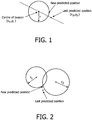
- a beacon-based object location apparatus provides the range (distance) of a detected object from a fixed beacon. In a two-dimensional space this resolves to an unknown point on a circle centred about one fixed beacon. When two beacons detect an object, the position resolves to two points where the beacons intersect. Three beacons allow range measurements to be converted into a single position. Techniques such as triangulation allow such range measurements, with errors to be converted into position.
- a line (of infinite length) is drawn along the axis from the last predicted position (x p , y p ) to the centre of the beacon (x c , y c ). This intersects with a circle drawn at the measured range r at 2 places. The closest point of intersection to the last predicted position is the new predicted position.
- beacon-based object location systems The accuracy of beacon-based object location systems is limited by the transmission ranges of the beacons, which are typically 10-30m. Therefore to provide for object location in a large or complexly shaped space (such as a home) would require several beacons. The need accurately to place and/or log the locations of such beacons is a strong disincentive to using the beacon-based apparatuses for home use.
- signal strength values are not ideal for this purpose because reflections, nulls and interruptions in the signal path render the distance estimates inaccurate.
- Such signal defects typically are caused eg. by building walls and other objects.
- beaconprinting as a step in setting up a beacon-based apparatus improves its accuracy to some extent.
- Another technique that can derive range from a beacon involves the measurement of the time-of-flight ("tof") of the signals received at the processor.
- the tof techniques require an ability to measure times of signal flights to nanosecond accuracy. This is difficult to achieve.
- multipaths ie. time-shifted echo signals caused by reflection of transmitted signals eg. from surfaces
- multipaths ie. time-shifted echo signals caused by reflection of transmitted signals eg. from surfaces
- Ultrawideband (“UWB”) methods are being developed. These are less sensitive to the effects of multipaths.
- All the known apparatuses require the establishment of the beacons and a step of allowing the apparatus to calculate the distance of the processor, a display device or another device serving as a base station, from each beacon; and in many cases the labelling, in a memory connected to the base station, of the beacons.
- Figure 4 summarises the accuracy and range of operation characteristics of various methods that in principle are suitable for use in object locating apparatuses. As illustrated by Figure 4 , however, those methods offering good location accuracy are associated with prohibitive infrastructure requirements; yet those whose infrastructure requirements are more reasonable for domestic use either fail to offer the accuracy needed to locate easily lost domestic items such as keys, building passes and mobile telephones; or they are accurate only over distances that are too short to be of practical benefit.
- WO-A-01/06401 discloses an arrangement in which tof measurements are employed to establish the distance of a so-called tagged object (ie. an object to be located) from a so-called "tag reader".
- a so-called tagged object ie. an object to be located
- tag reader must be at a fixed location in order for the apparatus to function.
- WO-A-01/06401 also discloses the use of signal strength determinations in object location techniques. However WO-A-01/06401 recognises the reduced accuracy available using signal strength evaluations.
- the range measuring mechanism is used to measure the distance from the device to be located, to a number of fixed nodes (base stations) situated around the home. Three or more base stations are required for this, depending on the detail of the ranging method employed. Once the measurements have been taken, techniques such as triangulation are then required to calculate the coordinates of the device to be located relative to the locations of the fixed nodes.
- the first stage of setting up the positioning system is to locate a number of beacons around the home. These should not be co-located, but placed at distributed positions around the home to improve the geometry of the positioning solution. Once the beacons have been positioned, their locations must be accurately determined relative to a fixed point in the home.
- an object location apparatus must include a map of the home (in the same way that an in-car GPS apparatus uses a CD-based map to convert longitude and latitude to road/town details).
- a method of indicating the location of a relatively mobile object comprising the steps of:
- the ability to combine tof and signal strength measurements in the method of the invention further improves the accuracy of the object location.
- the method includes, after carrying out Step (l):
- the data may for example include a verbal identifier, or a code.
- the base station or another processing device operatively associated with the apparatus used to carry out the method of the invention may include eg. software for converting such a code to a format that a user would readily recognise, ready for outputting to the user.
- Step (k) includes assessing data supplied to the processing device whereby the signal indicating whether the relatively mobile object is for the time being closer to the first or the second relatively immobile object includes data identifying:
- This sequence of steps advantageously allows the outputting of data, about the location of an object, that is "intuitive”, ie. readily understandable to the user.
- Step (j) includes determining the signal tof data by obtaining timing information between first and second devices using the steps of:
- Step (j) additionally or alternatively includes: a 1-beacon, 2-beacon or 3+-beacon RSSI determination.
- Step (k) of the method of the invention includes carrying out a contextual conversion using a look-up table stored in a memory device to interpret co-ordinates corresponding to the locations of the said objects, and generating one or more messages indicative of the identity of one or more said objects.
- Step (k) includes adhering a portable transmitter to each respective object, using an adhesive material.
- This sub-step helps to render the method of the invention convenient for a domestic user to carry out.
- the method includes the following step of, before step (a) :
- Step (m) includes:
- the method permits the long term storage and/or shipping of the portable transmitters, in a deactivated state, until it is necessary to activate them.
- Step (m) includes entering data via one or more of a keyboard, a keypad or a voice recognition device operatively connected to the processing device.
- the method includes, before carrying out Step (m):
- the set of classes may for example include:
- the method of the invention advantageously allows a user to "tag" easily lost (relatively mobile) objects; and relatively immobile objects, using language that is easy to follow.
- the method of the invention preferably includes, before Step (k):
- Step (k) also includes transmitting or displaying a message to a user via one or more of a display screen or a speech synthesiser that is operatively connected to the processing device.
- apparatus for indicating the location of a relatively mobile object comprising:
- the apparatus includes an input device for inputting to the processing device data that associate each portable transmitter with the object on which it is located.
- the input device includes one or more of a keyboard, a keypad or a voice input device operatively connected to the processing device.
- the processing device is programmable and is programmed to establish the distance of a said second transmitter from each of said first transmitters, obtaining timing information between first and second devices using the steps of:
- One embodiment involves device A measuring the Time-of-Flight from device B.
- Device B sends a known signal to device A, and includes a Timestamp to mark the time at which it was transmitted.
- Device A generates a local replica of the known signal, and correlates it with the signal received from device B. This correlation is achieved through Device A shifting its local replica in time until it matches with the signal received from device B, at which point it knows the Time-of-Arrival. It subtracts the Time-of-Transmission denoted by the Timestamp to give the Time-of-Flight. This assumes the clocks in device A and B are synchronized.
- the processing device is programmable and is programmed to establish the distance of a said second transmitter from each of said first transmitters, according to a 1-beacon, 2-beacon or 3+-beacon RSSI determination.
- a RSSI measurement is typically the voltage of the signal that has been received, amplified and converted into a integer number by a ADC.
- One embodiment that allows this RSSI measurement to be converted to range is using a lookup table. Under representative conditions measurements can be made of received RSSI values against ranges of 1m intervals from 0m to the furthest range of detection from a fixed beacon. This sampled data can be compiled into a lookup table allowing range to be derived from an RSSI measurement.
- the apparatus includes an adhesive material for adhering each said portable transmitter to a respective said object. It is also preferable that each said portable transmitter includes the adhesive material permanently secured thereto so as to present an adhesive surface for securing the transmitter to a said object.
- each said transmitter is switchable between a deactivated (non-transmitting) and an activated (transmitting) state.
- the apparatus includes a storage member for storing thereon each portable transmitter at least before first use, the storage member and the transmitter co-operating to maintain the transmitter in its deactivated state until its removal from the storage member on first use.
- the adhesive surface temporarily secures each transmitter to the storage member at least before first use of the transmitter.
- the storage member is or includes a flexible sheet to which each transmitter is secured before first use.
- the storage member also preferably includes a respective member that co-operates with each said transmitter stored thereon before first use in order to maintain the deactivated state of the said transmitter.
- the apparatus includes an output device operatively connected to the processing device.
- the processing device is programmable and is programmed to generate a prompt as to data requiring entry via the data entry device and as appropriate display or transmit the prompt via the output device.
- the output device is or includes one or more of a display screen or a speech synthesiser; and the processing device is programmable and is programmed to carry out a contextual conversion on data indicative of the said first transmitter to which the second transmitter is for the time being closer / closest.
- the foregoing features advantageously permit ready inputting of data and, more specifically, the outputting of object location information, via the apparatus.
- an apparatus 10 for indicating the location of a relatively mobile object relative to a relatively immobile object includes at least two first portable transmitters 11.
- Each first portable transmitter 11 is capable of generating and transmitting signals that are each characteristic of a respective, relatively immobile object.
- the first, portable transmitters 11 are each locatable on a relatively immobile object.
- two of the first, portable transmitters 11 are shown secured respectively on a table 12 and a television 13, each of which is an object that a householder moves only very infrequently (if at all).
- the transmitters 11 are locatable on any of a large number of relatively immobile objects such as but not limited to items of furniture; so-called "white goods"; filing cabinets; warehouse shelving; telephones; fixtures such as window sills and doorways; and office equipment such as photocopiers. Any number, greater than unity, of the first transmitters is theoretically possible within the scope of the invention.
- the apparatus 10 also includes at least one or more second portable transmitters 14 that are each capable of generating and transmitting signals that are respectively characteristic of a relatively mobile object, on which each such second, portable transmitter is locatable (ie. securable).
- a first such relatively mobile object is a first set of car keys 16, although it could be any of a very wide range of easily lost objects, or objects that are frequently moved and hence require tracking. Examples include but are not limited to keys other than for cars; sunglasses; wallets/purses; mobile telephones (which are easily lost when switched off); building passes and so-called "swipe" cards; passports; driving licences; cameras; portable, plug-in memory devices; MP3 and similar digital audio format players; children's toys and school equipment; and remote controllers eg. for audio and video equipment and powered doors/gates.
- FIG. 5 there is also shown a further, second portable transmitter 14 secured in the example shown to a second set 17 of car keys, although the or each further second portable transmitter is locatable on a similar range of objects as that exemplified above.
- the keys 16 are henceforth referred to as “the Jaguar keys”; and the keys 17 as “the Micra keys”.
- the registrations of the trade marks “Jaguar” and “Micra” are hereby acknowledged.
- the apparatus 10 additionally includes a receiver that in the preferred embodiment shown is a transceiver 18 that is capable of receiving the signals generated by the transmitters 11, 14.
- the respective signals are represented schematically by lines 11' (which refer to the signals from the transmitters 11) and 14' (which signify the signals from the transmitter 14).
- the transceiver 18 is secured to or otherwise operatively associated with the handset 19 of a DECT apparatus 21 that includes a base station 22.
- a DECT apparatus includes as a matter of routine a series of sub-components of the apparatus of the invention, and that are described hereinbelow.
- the receiver of the invention may in the alternative be secured or otherwise operatively connected to any of a range of other devices (such as for example personal computers, audio or video/TV equipment; game consoles, or even kitchen equipment such as microwave ovens and refrigerators); or it may be embodied as a discrete unit or series of functionally interconnected sub-units.
- devices such as for example personal computers, audio or video/TV equipment; game consoles, or even kitchen equipment such as microwave ovens and refrigerators
- it may be embodied as a discrete unit or series of functionally interconnected sub-units.
- receiver need not be embodied as part of a transceiver, but may instead be a discrete subcomponent.
- the apparatus 10 includes a processing device (that is not shown in Figure 5 by reason of lying within the housing of DECT handset 19 or base station 22) operatively connected to the receiver 18.
- the processing device is capable of establishing, using signal tof data and/or RSSI, the distances of each of the second transmitters 14 from each of at least two of the first transmitters 11 located on the relatively immobile objects 12, 13.
- the apparatus 10 also includes a signal generator.
- the signal generator is operatively connected to and located adjacent transceiver 18, although in other embodiments of the invention a discrete transmitter is possible.
- the signal generator is in the preferred embodiment operatively connected to the processing device within the housing of handset 19, but in other embodiments different connection and positioning arrangements are possible and within the scope of the invention.
- the signal generator is capable of generating a signal that is indicative of the identity of the said first, portable transmitter to which a selected said second, portable transmitter is, for the time being, closer.
- the DECT handset 19 includes in practice two input devices (the keypad 23 and microphone 24) by one, or in some embodiments, both, of which a user may enter data pertaining to the objects to which the transmitters 11, 14 are secured. Using one or more such devices a user can enter data indicative of the identity of each said object. By reason of the input device(s) being operatively connected to the processing device it is thereby possible uniquely to associate each transmitter 11, 14 with such an object.
- the processing device is part of a DECT handset input of such data is as implied by way of a keypad 23 and/or a microphone 24 that provides data to the processing device eg. following conditioning in a speech recognition device.
- the data input may occur via a keyboard forming part of eg. a personal computer or a TV-internet apparatus.
- the processing device is programmable and is programmed to carry out a signal tof method that, broadly, may be defined as obtaining timing information between first and second devices using the steps of:
- the first “device” is one of the transmitter 11,14; and the second “device” is the base station transceiver / processor combination 18.
- the programmable device also is programmed to carry out a 1-beacon, 2-beacon or 3-beacon RSSI determination as defined herein.
- An important feature of the invention, in making it easy for domestic users to employ, is that the portable transmitters must be small, light in weight and easy to apply to the various objects.
- each transmitter includes permanently secured thereto on an exterior surface a layer of adhesive material whereby it is readily possible to attach the transmitters to the objects.
- the transmitters are supplied to the user in a deactivated condition and are switchable to an activated condition when it is required to operate the apparatus.
- One preferred way of achieving this is to provide the transmitters as small (eg. postage stamp-sized) flexible laminae that are peelable (by way of characteristics of the adhesive layers providing for temporary adhesion of the transmitters) from eg. a flexible or rigid backing sheet to which the transmitters are electrically connected.
- the capacitance and/or resistance of the backing sheet may be used to hold a transmitter switch (eg. a resonant circuit) in a non-transmitting configuration.
- the backing sheet may constitute a storage member for storing the transmitters before first use, with the storage member and the transmitter co-operating to maintain the "off" condition of the transmitters until the user removes them from the sheet.
- the processing device has operatively associated therewith an output device.
- the output device may take either or both of two forms.
- the output device may be embodied as eg. a speech or tone synthesiser that transmits audible messages, especially spoken messages or meaningful tones, via a loudspeaker 26; or it may be a visible display such as that exemplified by reference numeral 27.
- combinations of output devices may be useful.
- the apparatus 10 of the invention may be programmed to respond by transmitting, via loudspeaker 26, the reply, "The Jaguar keys are on the table".
- the display 27 could display the word "TABLE” as a reminder.
- the loudspeaker might emit, under control of the processing device, a series of tones that meaningfully indicate (eg. through variations in frequency and/or timing) whether handset 19 is being moved closer to or further away from the Jaguar keys.
- the most helpful messages that the system generates are those relating the location of a selected, moveable object to that of one of the relatively immobile objects.
- a subsidiary aim is that of identifying over time, those objects which are capable of moving; and those which are relatively immobile.
- the software is able to avoid giving unhelpful messages such as, "The Jaguar keys are next to the Micra keys". Therefore the programming of the processor preferably includes adaptive learning functions.
- Switching on of the portable transmitters could be achieved by a connection that is broken when each one is removed from the book or other storage medium.
- the transmitter periodically sends a radio signal that includes a unique code that is programmed into the transmitter.
- the processor realises that the code is new and unknown and asks the user to type in the name of the object to which the transmitter is to be attached, using an SMS type of interface 23.
- the processor then adds a unique ID and the type name to its internal database. This registration process is repeated for a desired number of objects.
- the base station and the other DECT chargers may also count as objects in this sense.
- the DECT base station 22 will be in eg. a living room of the user's house, and additional DECT handsets and chargers, in the kitchen and a bedroom. However, the exact locations are not important in this description.
- the first and second portable transmitters 11, 14 resemble self-adhesive stamps stored eg. on a backing sheet or as the tearable pages of a booklet.
- the first and second transmitters may each be of the same design if desired. The user tears them out as desired and sticks one on each item whose position it is required to track; and on each relatively immobile object.
- the user attaches the transmitter to the object he has just named.
- the identity of object is then logged in the processor memory and its position can be calculated. The foregoing steps are repeated for each object to be included in the system.
- the programming of the processor permits the addition of objects to the processor memory at a later time, by repeating the method steps.
- the apparatus is now ready for use.
- the process of locating an object comprises two steps, with the second of these being optional.
- To locate an object the user picks up one of the handsets, and asks for the location of an object, eg. "Where are the Jaguar keys?".
- the system then works out where the keys are (according to a process outlined below), and responds using synthesised speech: "Next to the television in living room”.
- a second stage of search assistance is required, the user takes the handset and starts searching for the object.
- the handset emits a series of audible tones ("beeps"). As the user gets closer to the object, the handset beeps faster or in another meaningful way (ie. a kind of "hotter/colder” indication).
- the receiver 18 listens for signals from all of the objects in its data base and logs the signal strength and/or measures the time-of-flight of the RF signal (or some other measured RF parameter that is indicative of distance) from each received by the base station and the chargers. This time-of-flight and/or signal strength information is then compared with the same information for other objects in the database - see Table 1 below. In this way, the system is then able to work out whether the object to find is close to any of the other objects in the database. This will be the case if the object to find is generating a similar set of signals (time-of-flight, signal strength) as another object.
- Table 1 exemplifies some RSSI and tof values calculated during such a determination.
Landscapes
- Engineering & Computer Science (AREA)
- Radar, Positioning & Navigation (AREA)
- Remote Sensing (AREA)
- Physics & Mathematics (AREA)
- General Physics & Mathematics (AREA)
- Computer Networks & Wireless Communication (AREA)
- Mobile Radio Communication Systems (AREA)
- Emergency Alarm Devices (AREA)
- Near-Field Transmission Systems (AREA)
- Position Fixing By Use Of Radio Waves (AREA)
Claims (32)
- Procédé permettant d'indiquer l'emplacement d'un objet relativement mobile (16, 17) et comprenant les étapes suivantes :(a) la production d'un premier signal (11') qui est caractéristique d'un premier objet relativement immobile (12) ;(b) l'émission du premier signal (11') à partir du premier objet relativement immobile (12) ;(c) la détection du premier signal (11') au niveau d'un récepteur (18) ;(d) la production d'un deuxième signal (11') qui est caractéristique d'un deuxième objet relativement immobile (13) ;(e) l'émission du deuxième signal (11') à partir du deuxième objet relativement immobile (13) ;(f) la détection du deuxième signal (11') au niveau d'un récepteur (18) ;caractérisé en ce que le procédé comprend en outre les étapes suivantes :(g) la production d'un troisième signal (14') qui est caractéristique de l'objet relativement mobile (16, 17) ;(h) l'émission du troisième signal (14') à partir de l'objet relativement mobile (16, 17) ;(i) la détection du troisième signal (14') au niveau d'un récepteur (18) ;(j) l'actionnement d'un dispositif de traitement relié fonctionnellement au récepteur à l'aide de données correspondant au temps de vol (t-o-f) du signal et/ou d'informations sur la puissance du signal reçu (RSSI) pour établir la distance séparant l'objet relativement mobile (16, 17) respectivement des premier et deuxième objets relativement immobiles (12, 13) ; et(k) la production d'un signal indiquant si l'objet relativement mobile (16, 17) est plus proche du premier ou du deuxième objet relativement immobile (12, 13).
- Procédé selon la revendication 1 comportant, avant d'effectuer l'étape (a), l'étape suivante :(l) la mise en place sur chacun de l'objet relativement mobile (16, 17) et des premier et deuxième objets relativement immobiles (12, 13) d'un émetteur portable respectif (11, 14) qui est capable de produire et d'émettre ledit signal (11', 14') qui est caractéristique de l'objet (12, 13, 16, 17) sur lequel il se trouve.
- Procédé selon la revendication 2 comportant, après la réalisation de l'étape (l) :(m) l'étape de fourniture au dispositif de traitement, par l'intermédiaire d'un dispositif d'entrée, des données qui associent chacun desdits émetteurs portables (11, 14) à l'objet (12, 13, 16, 17) sur lequel il se trouve.
- Procédé selon la revendication 3 dans lequel l'étape (k) comporte l'évaluation des données fournies au dispositif de traitement, moyennant quoi le signal indiquant si l'objet relativement mobile est plus proche du premier ou du deuxième objet relativement immobile comprend des données qui identifient :(1) l'objet relativement mobile (16, 17) ; et(2) au moins l'objet relativement immobile (12, 13) dont il est plus proche.
- Procédé selon l'une quelconque des revendications précédentes dans lequel l'étape (j) comporte la détermination des données t-o-f du signal par obtention d'informations de synchronisation entre des premier et deuxième dispositifs à l'aide des étapes suivantes :- l'émission d'un signal de synchronisation du premier dispositif vers le deuxième dispositif à un instant t1 par rapport à l'horloge locale du premier dispositif et la mesure du temps d'arrivée t2 du signal en question au niveau du deuxième dispositif par rapport à l'horloge locale du deuxième dispositif ;- l'émission d'un signal de synchronisation du deuxième dispositif vers le premier dispositif à un instant t3 par rapport à l'horloge locale du deuxième dispositif et la mesure du temps d'arrivée t4 du signal en question au niveau du premier dispositif par rapport à l'horloge locale du premier dispositif ; et- l'assemblage des valeurs de t1, t2, t3 et t4 dans un seul dispositif.
- Procédé selon l'une quelconque des revendications précédentes dans lequel l'étape (j) comporte une détermination de RSSI avec 1 balise, 2 balises ou 3 balises ou plus.
- Procédé selon l'une quelconque des revendications précédentes dans lequel l'étape (k) comprend :
la réalisation d'une opération de consultation à l'aide d'une table de consultation stockée dans un périphérique mémoire pour interpréter des coordonnées correspondant aux emplacements desdits objets, et la production d'un ou plusieurs messages indiquant une identité d'un ou plusieurs desdits objets. - Procédé selon la revendication 2 ou une quelconque revendication précédente dépendante de celle-ci, dans lequel l'étape (l) comporte le collage d'un émetteur portable sur chaque objet respectif, à l'aide d'un matériau adhésif.
- Procédé selon la revendication 2 ou une quelconque revendication précédente dépendante de celle-ci, comportant avant l'étape (a), l'étape suivante :(n) l'activation de chacun desdits émetteurs portables à partir d'un état désactivé.
- Procédé selon la revendication 9 dans lequel l'étape (n) comporte :(o) le retrait de chacun desdits émetteurs portables d'un emplacement de stockage, où chacun desdits émetteurs portables est maintenu dans ledit état désactivé, ledit retrait de cette étape (o) provoquant ladite activation.
- Procédé selon la revendication 3 ou une quelconque revendication précédente dépendante de celle-ci, dans lequel l'étape (m) comporte l'entrée de données par l'intermédiaire d'un ou plusieurs moyens parmi un clavier, un pavé numérique ou un dispositif d'entrée vocale reliés fonctionnellement au dispositif de traitement.
- Procédé selon la revendication 3 ou une quelconque revendication précédente comportant, avant l'étape (m) :(p) la proposition, à un utilisateur, d'une classe de données à entrer, la classe de données étant choisie parmi un ensemble de classes.
- Procédé selon la revendication 12 dans lequel l'ensemble de classes comprend au moins :des objets relativement mobiles ;des objets relativement immobiles ; etdes stations de base.
- Procédé selon l'une quelconque des revendications précédentes comportant, avant l'étape (k) :(q) l'interrogation du dispositif de traitement par l'intermédiaire d'un dispositif d'entrée quant à l'emplacement dudit objet relativement mobile.
- Procédé selon la revendication 14 dans lequel l'étape (q) comporte l'interrogation du dispositif de traitement par l'intermédiaire d'un ou plusieurs moyens parmi un clavier, un pavé numérique ou un dispositif de reconnaissance vocale reliés fonctionnellement au récepteur.
- Procédé selon l'une quelconque des revendications précédentes dans lequel l'étape (k) comporte l'émission ou l'affichage d'un message destiné à un utilisateur par l'intermédiaire d'un ou plusieurs moyens parmi un écran d'affichage ou un synthétiseur vocal qui est relié fonctionnellement au dispositif de traitement.
- Appareil permettant d'indiquer l'emplacement d'un objet relativement mobile (16, 17), comprenant :deux ou plusieurs premiers émetteurs portables (11) qui sont capables de produire et d'émettre des signaux (11') caractéristiques chacun d'un objet relativement immobile (12, 13) respectif, les premiers émetteurs portables (11) pouvant chacun se trouver sur un desdits objets relativement immobiles (12, 13) ;un ou plusieurs deuxièmes émetteurs portables (14) qui sont capables de produire et d'émettre des signaux (14') caractéristiques chacun d'un desdits objets relativement mobiles (16, 17), le ou chacun desdits deuxièmes émetteurs portables (14) pouvant se trouver sur un desdits objets relativement mobiles (16, 17) respectifs ;un récepteur (18) qui est capable de recevoir les signaux (11' ; 14') produits par les émetteurs (11, 14) ;un dispositif de traitement qui est capable d'établir, à l'aide de données t-o-f et/ou de RSSI des signaux, la distance séparant l'un desdits deuxièmes émetteurs (14), situé sur un desdits objets relativement mobiles, de chacun desdits deux premiers émetteurs (11) situés sur lesdits objets relativement immobiles (12, 13) respectifs ; etun générateur de signal capable de produire un signal indiquant ledit premier émetteur (11) dont ledit deuxième émetteur portable (14) est plus proche.
- Appareil selon la revendication 17 comportant un dispositif d'entrée permettant d'entrer dans le dispositif de traitement des données qui associent chaque émetteur portable à l'objet sur lequel il se trouve.
- Appareil selon la revendication 18 dans lequel le dispositif d'entrée comprend un ou plusieurs dispositifs parmi un clavier, un pavé numérique ou un dispositif d'entrée vocale reliés fonctionnellement au dispositif de traitement.
- Appareil selon l'une quelconque des revendications 17 à 19 dans lequel le dispositif de traitement est programmable et est programmé pour établir la distance séparant un desdits deuxièmes émetteurs de chacun desdits premiers émetteurs, en obtenant des informations de synchronisation entre des premier et deuxième dispositifs à l'aide des étapes suivantes :- l'émission d'un signal de synchronisation du premier dispositif vers le deuxième dispositif à un instant t1 par rapport à l'horloge locale du premier dispositif et la mesure du temps d'arrivée t2 du signal en question au niveau du deuxième dispositif par rapport à l'horloge locale du deuxième dispositif ;- l'émission d'un signal de synchronisation du deuxième dispositif vers le premier dispositif à un instant t3 par rapport à l'horloge locale du deuxième dispositif et la mesure du temps d'arrivée t4 du signal en question au niveau du premier dispositif par rapport à l'horloge locale du premier dispositif ; et- l'assemblage des valeurs de t1, t2, t3 et t4 dans un seul dispositif.
- Appareil selon l'une quelconque des revendications 17 à 20 dans lequel le dispositif de traitement est programmable et est programmé pour établir la distance séparant un desdits deuxièmes émetteurs de chacun desdits premiers émetteurs, à partir d'une détermination de RSSI avec 1 balise, 2 balises ou 3 balises ou plus.
- Appareil selon l'une quelconque des revendications 17 à 21 comportant un matériau adhésif permettant de coller chacun desdits émetteurs portables sur un desdits objets respectifs.
- Appareil selon la revendication 22 dans lequel chacun desdits émetteurs portables comporte le matériau adhésif fixé à demeure sur celui-ci de manière à présenter une surface adhésive permettant de fixer l'émetteur à un desdits objets.
- Appareil selon l'une quelconque des revendications 17 à 22 dans lequel chacun desdits émetteurs peut passer d'un état désactivé (non émetteur) à un état activé (émetteur).
- Appareil selon la revendication 24 comportant un élément de stockage permettant de stocker sur celui-ci chaque émetteur portable au moins avant une première utilisation, la coopération entre l'élément de stockage et l'émetteur étant destinée à maintenir l'émetteur dans son état désactivé jusqu'à son retrait de l'élément de stockage lors d'une première utilisation.
- Appareil selon la revendication 23 et la revendication 25 dans lequel la surface adhésive fixe de façon temporaire chaque émetteur à l'élément de stockage au moins avant une première utilisation de l'émetteur.
- Appareil selon la revendication 25 ou la revendication 26 dans lequel l'élément de stockage est ou comporte une feuille souple à laquelle est fixé chaque émetteur avant une première utilisation.
- Appareil selon la revendication 25 ou une quelconque revendication précédente dépendante de celle-ci, dans lequel l'élément de stockage comporte un élément respectif qui coopère avec chacun desdits émetteurs stocké sur celui-ci avant une première utilisation afin de maintenir l'état désactivé dudit émetteur.
- Appareil selon l'une quelconque des revendications 17 à 28 comportant un dispositif de sortie relié fonctionnellement au dispositif de traitement.
- Appareil selon la revendication 29 lorsqu'elle dépend de la revendication 18, dans lequel le dispositif de traitement est programmable et est programmé pour produire une proposition de données à entrer par l'intermédiaire du dispositif d'entrée de données et, selon le cas, pour afficher ou émettre la proposition par l'intermédiaire du dispositif de sortie.
- Appareil selon la revendication 29 ou la revendication 30 dans lequel le dispositif de sortie est ou comporte un ou plusieurs d'un écran d'affichage ou d'un synthétiseur vocal.
- Appareil selon l'une quelconque des revendications précédentes dans lequel le dispositif de traitement est programmable et est programmé pour effectuer une opération de consultation sur des données indiquant ledit premier émetteur dont le deuxième émetteur est plus proche.
Applications Claiming Priority (2)
| Application Number | Priority Date | Filing Date | Title |
|---|---|---|---|
| GBGB0324098.3A GB0324098D0 (en) | 2003-10-15 | 2003-10-15 | Method and apparatus for indicating the location of an object |
| PCT/IB2004/052056 WO2005038480A1 (fr) | 2003-10-15 | 2004-10-12 | Procede et appareil permettant d'indiquer l'emplacement d'un objet |
Publications (2)
| Publication Number | Publication Date |
|---|---|
| EP1676146A1 EP1676146A1 (fr) | 2006-07-05 |
| EP1676146B1 true EP1676146B1 (fr) | 2018-05-30 |
Family
ID=29559298
Family Applications (1)
| Application Number | Title | Priority Date | Filing Date |
|---|---|---|---|
| EP04770227.9A Revoked EP1676146B1 (fr) | 2003-10-15 | 2004-10-12 | Procede et appareil permettant d'indiquer l'emplacement d'un objet |
Country Status (7)
| Country | Link |
|---|---|
| US (1) | US7577444B2 (fr) |
| EP (1) | EP1676146B1 (fr) |
| JP (1) | JP4988349B2 (fr) |
| KR (1) | KR20070019953A (fr) |
| CN (1) | CN100594389C (fr) |
| GB (1) | GB0324098D0 (fr) |
| WO (1) | WO2005038480A1 (fr) |
Families Citing this family (50)
| Publication number | Priority date | Publication date | Assignee | Title |
|---|---|---|---|---|
| EP1746433B1 (fr) * | 2005-07-18 | 2007-08-29 | Gerald Kampel | Procédé et dispositif pour la détection de personnes enseveliés |
| US7576645B1 (en) * | 2005-08-01 | 2009-08-18 | Stanley Louis Lugerner | Remote control finder |
| FR2890772B1 (fr) * | 2005-09-09 | 2012-03-16 | Thales Sa | Procede et systeme de localisation d'individus a l'interieur d'un batiment |
| JP2007174244A (ja) * | 2005-12-21 | 2007-07-05 | Canon Inc | 無線通信装置および測距方法 |
| US20090022138A1 (en) * | 2006-11-20 | 2009-01-22 | Visible Assets Inc. | Multiplexing protocol for large, high security areas with 3d localization |
| US7786935B2 (en) * | 2007-01-07 | 2010-08-31 | Connectsoft, Inc. | Method and system for inferring a location of a mobile computing device |
| KR100939354B1 (ko) * | 2007-11-28 | 2010-01-29 | 한국전자통신연구원 | 액세스 포인트를 이용한 위치 측정 방법 및 그 장치 |
| US9262912B2 (en) | 2008-02-25 | 2016-02-16 | Checkpoint Systems, Inc. | Localizing tagged assets using modulated backscatter |
| US8212653B1 (en) | 2008-03-20 | 2012-07-03 | The General Hospital Corp. | Protected zone system |
| US8384522B2 (en) * | 2008-09-03 | 2013-02-26 | Commscope, Inc. Of North Carolina | Radio frequency identification triangulation systems for communications patching systems and related methods of determining patch cord connectivity information |
| US20100176985A1 (en) * | 2009-01-13 | 2010-07-15 | Lucent Technologies Inc. | Systems and methods of global positioning systems using wireless networks |
| US8547220B1 (en) * | 2009-06-18 | 2013-10-01 | The General Hospital Corporation | Ultrasonic compliance zone system |
| US8164439B2 (en) * | 2009-06-18 | 2012-04-24 | The General Hospital Corp. | Ultrasonic compliance zone system |
| JP2011017685A (ja) * | 2009-07-10 | 2011-01-27 | Kenwood Corp | 測位システム及び制御方法 |
| JP2011017684A (ja) * | 2009-07-10 | 2011-01-27 | Kenwood Corp | 測位システム及び制御方法 |
| US8144015B2 (en) * | 2009-09-23 | 2012-03-27 | Microsoft Corporation | Power efficient object detection with selective polling |
| WO2011041786A2 (fr) * | 2009-10-02 | 2011-04-07 | Kevin Perry | Dragonne |
| US8254958B2 (en) * | 2009-12-30 | 2012-08-28 | Glenn Carl Johnson | Audible key locator system |
| US8983537B2 (en) | 2009-12-30 | 2015-03-17 | Glenn Johnson | Object locator system and method |
| KR101644598B1 (ko) * | 2010-02-12 | 2016-08-02 | 삼성전자주식회사 | 복수의 디스플레이 장치를 포함하는 영상 시스템 제어방법 |
| US8140258B1 (en) | 2010-03-02 | 2012-03-20 | The General Hospital Corporation | Wayfinding system |
| US20120013468A1 (en) * | 2010-07-16 | 2012-01-19 | George Olah | Wireless object localization and registration system and method |
| US20120021764A1 (en) * | 2010-07-23 | 2012-01-26 | Quantum Dimension Inc. | System and Method for Robust Navigation and Communication Via A Cooperative Ad-hoc Network |
| KR101470775B1 (ko) * | 2010-10-13 | 2014-12-08 | 인텔 코포레이션 | Wi-fi 신호 기반 근접 검출을 위한 메커니즘 |
| US9476966B2 (en) * | 2011-12-05 | 2016-10-25 | Qualcomm Incorporated | Methods and apparatuses for use in selecting a transmitting device for use in a positioning function |
| US10229610B2 (en) * | 2012-03-30 | 2019-03-12 | Qualcomm Incorporated | Contextual awareness using relative positions of mobile devices |
| GB201214976D0 (en) | 2012-08-22 | 2012-10-03 | Connect In Ltd | Monitoring system |
| US9055923B2 (en) | 2012-10-19 | 2015-06-16 | Carestream Health, Inc. | Computed radiography positioning method and system |
| RU2660824C2 (ru) | 2013-06-04 | 2018-07-10 | Конинклейке Филипс Н.В. | Улучшенное измерение расстояния с использованием времени пролета |
| US9504425B2 (en) * | 2013-12-16 | 2016-11-29 | Verily Life Sciences Llc | Method of location coordination via wireless protocol between multiple devices |
| US20150264530A1 (en) * | 2014-03-12 | 2015-09-17 | Gaby Prechner | Access point initiated time-of-flight positioning |
| US9674668B2 (en) | 2014-03-21 | 2017-06-06 | Htc Corporation | Method, electronic apparatus and computer readable medium for determining relative position of apparatus |
| CN104950284B (zh) * | 2014-03-24 | 2019-04-19 | 宏达国际电子股份有限公司 | 装置相对位置的判定方法及电子装置 |
| US9734682B2 (en) | 2015-03-02 | 2017-08-15 | Enovate Medical, Llc | Asset management using an asset tag device |
| US9679463B1 (en) * | 2015-09-22 | 2017-06-13 | Tanasia Clark | Remote control-finding device |
| DE102016102402A1 (de) * | 2016-02-11 | 2017-08-17 | Rwe Effizienz Gmbh | Heimautomatisierungssystem |
| CA3025715A1 (fr) | 2016-05-31 | 2017-12-07 | Koninklijke Philips N.V. | Georeperage base sur des signaux multiples et configuration |
| US9767673B1 (en) | 2016-06-07 | 2017-09-19 | Paul Clip | System and method for detecting that an open bag is being carried |
| WO2018100892A1 (fr) | 2016-11-29 | 2018-06-07 | 株式会社村田製作所 | Appareil d'estimation de position et procédé d'estimation de position |
| EP3349516B1 (fr) | 2017-01-11 | 2020-11-11 | ABL IP Holding LLC | Suivi d'actifs au moyen d'étiquettes sans fil actives communiquant par l'intermédiaire d'un réseau local de balises connectées |
| EP3635430B1 (fr) | 2017-05-31 | 2024-07-03 | Hexagon Technology Center GmbH | Procédé et appareil pour déterminer l'emplacement d'un objet statique |
| ES2860776T3 (es) | 2017-09-07 | 2021-10-05 | Signify Holding Bv | Sistema de posicionamiento interior para objetos móviles |
| US10210353B1 (en) | 2018-03-09 | 2019-02-19 | Abl Ip Holding Llc | Asset tag tracking system and network architecture |
| US10502811B2 (en) | 2018-03-09 | 2019-12-10 | Abl Ip Holding Llc | Network architecture, radio frequency based asset tracking and/or location estimation methods and systems |
| US10422848B1 (en) | 2018-03-09 | 2019-09-24 | Abl Ip Holding Llc | More accurate asset tag locating of radio frequency devices |
| EP3726241A1 (fr) * | 2019-04-19 | 2020-10-21 | Siemens Mobility GmbH | Procédé et système de localisation d'un objet |
| US10959050B2 (en) * | 2019-04-24 | 2021-03-23 | International Business Machines Corporation | Action based object location system |
| DE102019111245A1 (de) * | 2019-04-30 | 2020-11-05 | Bayerische Motoren Werke Aktiengesellschaft | Vorrichtung zum Bestimmen der Entfernung von einem Sender zu einem Empfänger |
| US11197262B2 (en) * | 2019-08-02 | 2021-12-07 | Dell Products, Lp | Systems and methods of room profiling using wireless local area networks |
| US11950567B2 (en) | 2021-03-04 | 2024-04-09 | Sky View Environmental Service Llc | Condor monitoring systems and related methods |
Citations (9)
| Publication number | Priority date | Publication date | Assignee | Title |
|---|---|---|---|---|
| US5920261A (en) | 1996-12-31 | 1999-07-06 | Design Vision Inc. | Methods and apparatus for tracking and displaying objects |
| US5936527A (en) | 1998-02-10 | 1999-08-10 | E-Tag Systems, Inc. | Method and apparatus for locating and tracking documents and other objects |
| US6154139A (en) | 1998-04-21 | 2000-11-28 | Versus Technology | Method and system for locating subjects within a tracking environment |
| WO2001006401A1 (fr) | 1999-07-15 | 2001-01-25 | Pinpoint Corporation | Procede et appareil de lecture d'etiquette d'identification mobile |
| WO2001011386A1 (fr) | 1999-08-05 | 2001-02-15 | Koninklijke Philips Electronics N.V. | Systeme et procede de localisation d'emplacement |
| WO2001034264A1 (fr) | 1999-11-11 | 2001-05-17 | Scientific Generics Limited | Systeme de localisation acoustique |
| US20030146835A1 (en) | 2000-03-31 | 2003-08-07 | Ge Medical Systems Information Technologies, Inc. | Object location monitoring within buildings |
| WO2004002185A1 (fr) | 2002-06-24 | 2003-12-31 | Intel Corporation | Configuration de point d'acces a un reseau sans fil |
| US20040108954A1 (en) | 2001-10-18 | 2004-06-10 | Richley Edward A. | Object location system and method |
Family Cites Families (11)
| Publication number | Priority date | Publication date | Assignee | Title |
|---|---|---|---|---|
| KR100409187B1 (ko) * | 1994-08-16 | 2004-03-10 | 소니 가부시끼 가이샤 | 텔레비젼신호수신및프로그램절환장치와방법과원격조정기 |
| DE59601731D1 (de) * | 1995-09-01 | 1999-05-27 | Konle Tilmar | System zur lagebestimmung von beweglichen objekten |
| EP0908022A2 (fr) * | 1996-07-12 | 1999-04-14 | Eagle Eye Technologies Inc. | Procede et appareil pour geolocalisation precise |
| RU2142117C1 (ru) * | 1998-09-17 | 1999-11-27 | Московский государственный университет леса | Микрорезонаторный волоконно-оптический датчик угловых перемещений |
| US6963283B1 (en) * | 2000-02-15 | 2005-11-08 | Gonzalez Thomas A | Child alert system |
| GB0004371D0 (en) * | 2000-02-24 | 2000-04-12 | Koninkl Philips Electronics Nv | GPS receiver and mobile unit incorporating the same |
| DE10147899A1 (de) * | 2001-09-28 | 2003-04-10 | Siemens Ag | TD-CDMA-Übertragungssystem |
| JP3710416B2 (ja) * | 2001-12-19 | 2005-10-26 | 日本電信電話株式会社 | 位置検出システム |
| DE20309282U1 (de) * | 2002-03-21 | 2003-10-02 | Pöllet, Wilfried, 90596 Schwanstetten | Einrichtung zum Auffinden eines abgestellten Gegenstandes, insbesondere eines abgestellten Fahrzeugs,von einem aktuellen Standort aus |
| US7006838B2 (en) * | 2002-11-27 | 2006-02-28 | Cognio, Inc. | System and method for locating sources of unknown wireless radio signals |
| US7974633B2 (en) * | 2006-08-18 | 2011-07-05 | Andrew, Llc | System and method for single sensor geolocation |
-
2003
- 2003-10-15 GB GBGB0324098.3A patent/GB0324098D0/en not_active Ceased
-
2004
- 2004-10-12 US US10/575,580 patent/US7577444B2/en not_active Expired - Lifetime
- 2004-10-12 WO PCT/IB2004/052056 patent/WO2005038480A1/fr not_active Ceased
- 2004-10-12 JP JP2006534887A patent/JP4988349B2/ja not_active Expired - Lifetime
- 2004-10-12 KR KR1020067007134A patent/KR20070019953A/ko not_active Withdrawn
- 2004-10-12 EP EP04770227.9A patent/EP1676146B1/fr not_active Revoked
- 2004-10-12 CN CN200480030319A patent/CN100594389C/zh not_active Expired - Lifetime
Patent Citations (9)
| Publication number | Priority date | Publication date | Assignee | Title |
|---|---|---|---|---|
| US5920261A (en) | 1996-12-31 | 1999-07-06 | Design Vision Inc. | Methods and apparatus for tracking and displaying objects |
| US5936527A (en) | 1998-02-10 | 1999-08-10 | E-Tag Systems, Inc. | Method and apparatus for locating and tracking documents and other objects |
| US6154139A (en) | 1998-04-21 | 2000-11-28 | Versus Technology | Method and system for locating subjects within a tracking environment |
| WO2001006401A1 (fr) | 1999-07-15 | 2001-01-25 | Pinpoint Corporation | Procede et appareil de lecture d'etiquette d'identification mobile |
| WO2001011386A1 (fr) | 1999-08-05 | 2001-02-15 | Koninklijke Philips Electronics N.V. | Systeme et procede de localisation d'emplacement |
| WO2001034264A1 (fr) | 1999-11-11 | 2001-05-17 | Scientific Generics Limited | Systeme de localisation acoustique |
| US20030146835A1 (en) | 2000-03-31 | 2003-08-07 | Ge Medical Systems Information Technologies, Inc. | Object location monitoring within buildings |
| US20040108954A1 (en) | 2001-10-18 | 2004-06-10 | Richley Edward A. | Object location system and method |
| WO2004002185A1 (fr) | 2002-06-24 | 2003-12-31 | Intel Corporation | Configuration de point d'acces a un reseau sans fil |
Non-Patent Citations (1)
| Title |
|---|
| CAPKUN S ET AL.: "GPS-FREE POSITIONING IN MOBILE AD-HOC NETWORKS", PROCEEDINGS OF THE 34TH ANNUAL HAWAII INTERNATIONAL CONFERENCE ON SYSTEM SCIENCE, 3 January 2001 (2001-01-03), pages 1 - 10, XP008001836 |
Also Published As
| Publication number | Publication date |
|---|---|
| JP2007508773A (ja) | 2007-04-05 |
| KR20070019953A (ko) | 2007-02-16 |
| EP1676146A1 (fr) | 2006-07-05 |
| GB0324098D0 (en) | 2003-11-19 |
| WO2005038480A1 (fr) | 2005-04-28 |
| US7577444B2 (en) | 2009-08-18 |
| JP4988349B2 (ja) | 2012-08-01 |
| CN1867836A (zh) | 2006-11-22 |
| CN100594389C (zh) | 2010-03-17 |
| US20070052534A1 (en) | 2007-03-08 |
Similar Documents
| Publication | Publication Date | Title |
|---|---|---|
| EP1676146B1 (fr) | Procede et appareil permettant d'indiquer l'emplacement d'un objet | |
| EP1700135B1 (fr) | Systeme de localisation avec surveillance d'etalonnage | |
| US20240426960A1 (en) | Sensor fusion network to disambiguate angle of arrival | |
| EP1525770B1 (fr) | Configuration de point d'acces a un reseau sans fil | |
| Vossiek et al. | Wireless local positioning | |
| RU2697838C1 (ru) | Система позиционирования | |
| US8140016B2 (en) | Wireless communication terminals and methods using acoustic ranging synchronized to RF communication signals | |
| US20100090899A1 (en) | Method and system for positioning object with adaptive resolution | |
| CN102725648A (zh) | 用于确定某位置与基准位置的一致性的设备和方法 | |
| EP3092830B2 (fr) | Rétroaction dans un système de positionnement | |
| JP2004507991A (ja) | ゾーン・ベースの無線周波数識別 | |
| AU2005325688A1 (en) | RFID reader management system and method | |
| US12259487B2 (en) | Techniques for localizing an electronic device | |
| Li et al. | Hybrid indoor location positioning system | |
| CN104101863A (zh) | 基于智能移动设备的定位系统和定位方法 | |
| CN100401092C (zh) | 一种无线定位的方法及其系统 | |
| US8669862B2 (en) | Communication device including local location information | |
| US20190141663A1 (en) | Portable-device-locating system that uses room-level motion sensors and rssi measurements to determine precise room-location | |
| CN101194528B (zh) | 定位系统和定位方法以及移动位置数据发送器 | |
| Hammer et al. | Performance evaluation of 3d-position estimation systems | |
| JP2013152133A (ja) | 測位システム | |
| EP3982145A1 (fr) | Système de localisation intérieure | |
| Gosai et al. | Real time location based tracking using WiFi Signals | |
| Knauth et al. | iLOC: a localisation system for visitor tracking & guidance | |
| US7382317B1 (en) | Two-stage location system |
Legal Events
| Date | Code | Title | Description |
|---|---|---|---|
| PUAI | Public reference made under article 153(3) epc to a published international application that has entered the european phase |
Free format text: ORIGINAL CODE: 0009012 |
|
| 17P | Request for examination filed |
Effective date: 20060515 |
|
| AK | Designated contracting states |
Kind code of ref document: A1 Designated state(s): AT BE BG CH CY CZ DE DK EE ES FI FR GB GR HU IE IT LI LU MC NL PL PT RO SE SI SK TR |
|
| DAX | Request for extension of the european patent (deleted) | ||
| 17Q | First examination report despatched |
Effective date: 20090914 |
|
| RAP1 | Party data changed (applicant data changed or rights of an application transferred) |
Owner name: KONINKLIJKE PHILIPS N.V. |
|
| GRAP | Despatch of communication of intention to grant a patent |
Free format text: ORIGINAL CODE: EPIDOSNIGR1 |
|
| STAA | Information on the status of an ep patent application or granted ep patent |
Free format text: STATUS: GRANT OF PATENT IS INTENDED |
|
| INTG | Intention to grant announced |
Effective date: 20171220 |
|
| RIN1 | Information on inventor provided before grant (corrected) |
Inventor name: BIRD, NEIL, C., PHILIPS INT. PROPERTY & STANDARDS Inventor name: SIMONS, PAUL, R., PHILIPS I. PROPERTY & STANDARDS |
|
| GRAS | Grant fee paid |
Free format text: ORIGINAL CODE: EPIDOSNIGR3 |
|
| GRAA | (expected) grant |
Free format text: ORIGINAL CODE: 0009210 |
|
| STAA | Information on the status of an ep patent application or granted ep patent |
Free format text: STATUS: THE PATENT HAS BEEN GRANTED |
|
| AK | Designated contracting states |
Kind code of ref document: B1 Designated state(s): AT BE BG CH CY CZ DE DK EE ES FI FR GB GR HU IE IT LI LU MC NL PL PT RO SE SI SK TR |
|
| REG | Reference to a national code |
Ref country code: GB Ref legal event code: FG4D |
|
| REG | Reference to a national code |
Ref country code: CH Ref legal event code: EP |
|
| REG | Reference to a national code |
Ref country code: AT Ref legal event code: REF Ref document number: 1004171 Country of ref document: AT Kind code of ref document: T Effective date: 20180615 |
|
| REG | Reference to a national code |
Ref country code: IE Ref legal event code: FG4D |
|
| REG | Reference to a national code |
Ref country code: DE Ref legal event code: R096 Ref document number: 602004052765 Country of ref document: DE |
|
| REG | Reference to a national code |
Ref country code: NL Ref legal event code: MP Effective date: 20180530 |
|
| REG | Reference to a national code |
Ref country code: FR Ref legal event code: PLFP Year of fee payment: 15 |
|
| PG25 | Lapsed in a contracting state [announced via postgrant information from national office to epo] |
Ref country code: FI Free format text: LAPSE BECAUSE OF FAILURE TO SUBMIT A TRANSLATION OF THE DESCRIPTION OR TO PAY THE FEE WITHIN THE PRESCRIBED TIME-LIMIT Effective date: 20180530 Ref country code: BG Free format text: LAPSE BECAUSE OF FAILURE TO SUBMIT A TRANSLATION OF THE DESCRIPTION OR TO PAY THE FEE WITHIN THE PRESCRIBED TIME-LIMIT Effective date: 20180830 Ref country code: CY Free format text: LAPSE BECAUSE OF FAILURE TO SUBMIT A TRANSLATION OF THE DESCRIPTION OR TO PAY THE FEE WITHIN THE PRESCRIBED TIME-LIMIT Effective date: 20180530 Ref country code: SE Free format text: LAPSE BECAUSE OF FAILURE TO SUBMIT A TRANSLATION OF THE DESCRIPTION OR TO PAY THE FEE WITHIN THE PRESCRIBED TIME-LIMIT Effective date: 20180530 Ref country code: ES Free format text: LAPSE BECAUSE OF FAILURE TO SUBMIT A TRANSLATION OF THE DESCRIPTION OR TO PAY THE FEE WITHIN THE PRESCRIBED TIME-LIMIT Effective date: 20180530 |
|
| PG25 | Lapsed in a contracting state [announced via postgrant information from national office to epo] |
Ref country code: GR Free format text: LAPSE BECAUSE OF FAILURE TO SUBMIT A TRANSLATION OF THE DESCRIPTION OR TO PAY THE FEE WITHIN THE PRESCRIBED TIME-LIMIT Effective date: 20180831 |
|
| REG | Reference to a national code |
Ref country code: AT Ref legal event code: MK05 Ref document number: 1004171 Country of ref document: AT Kind code of ref document: T Effective date: 20180530 |
|
| PG25 | Lapsed in a contracting state [announced via postgrant information from national office to epo] |
Ref country code: NL Free format text: LAPSE BECAUSE OF FAILURE TO SUBMIT A TRANSLATION OF THE DESCRIPTION OR TO PAY THE FEE WITHIN THE PRESCRIBED TIME-LIMIT Effective date: 20180530 |
|
| PG25 | Lapsed in a contracting state [announced via postgrant information from national office to epo] |
Ref country code: PL Free format text: LAPSE BECAUSE OF FAILURE TO SUBMIT A TRANSLATION OF THE DESCRIPTION OR TO PAY THE FEE WITHIN THE PRESCRIBED TIME-LIMIT Effective date: 20180530 Ref country code: EE Free format text: LAPSE BECAUSE OF FAILURE TO SUBMIT A TRANSLATION OF THE DESCRIPTION OR TO PAY THE FEE WITHIN THE PRESCRIBED TIME-LIMIT Effective date: 20180530 Ref country code: DK Free format text: LAPSE BECAUSE OF FAILURE TO SUBMIT A TRANSLATION OF THE DESCRIPTION OR TO PAY THE FEE WITHIN THE PRESCRIBED TIME-LIMIT Effective date: 20180530 Ref country code: AT Free format text: LAPSE BECAUSE OF FAILURE TO SUBMIT A TRANSLATION OF THE DESCRIPTION OR TO PAY THE FEE WITHIN THE PRESCRIBED TIME-LIMIT Effective date: 20180530 Ref country code: RO Free format text: LAPSE BECAUSE OF FAILURE TO SUBMIT A TRANSLATION OF THE DESCRIPTION OR TO PAY THE FEE WITHIN THE PRESCRIBED TIME-LIMIT Effective date: 20180530 Ref country code: CZ Free format text: LAPSE BECAUSE OF FAILURE TO SUBMIT A TRANSLATION OF THE DESCRIPTION OR TO PAY THE FEE WITHIN THE PRESCRIBED TIME-LIMIT Effective date: 20180530 Ref country code: SK Free format text: LAPSE BECAUSE OF FAILURE TO SUBMIT A TRANSLATION OF THE DESCRIPTION OR TO PAY THE FEE WITHIN THE PRESCRIBED TIME-LIMIT Effective date: 20180530 |
|
| REG | Reference to a national code |
Ref country code: DE Ref legal event code: R026 Ref document number: 602004052765 Country of ref document: DE |
|
| PG25 | Lapsed in a contracting state [announced via postgrant information from national office to epo] |
Ref country code: IT Free format text: LAPSE BECAUSE OF FAILURE TO SUBMIT A TRANSLATION OF THE DESCRIPTION OR TO PAY THE FEE WITHIN THE PRESCRIBED TIME-LIMIT Effective date: 20180530 |
|
| PLBI | Opposition filed |
Free format text: ORIGINAL CODE: 0009260 |
|
| PLAX | Notice of opposition and request to file observation + time limit sent |
Free format text: ORIGINAL CODE: EPIDOSNOBS2 |
|
| 26 | Opposition filed |
Opponent name: GUDER, ANDRE Effective date: 20190227 |
|
| PLBB | Reply of patent proprietor to notice(s) of opposition received |
Free format text: ORIGINAL CODE: EPIDOSNOBS3 |
|
| PG25 | Lapsed in a contracting state [announced via postgrant information from national office to epo] |
Ref country code: SI Free format text: LAPSE BECAUSE OF FAILURE TO SUBMIT A TRANSLATION OF THE DESCRIPTION OR TO PAY THE FEE WITHIN THE PRESCRIBED TIME-LIMIT Effective date: 20180530 |
|
| REG | Reference to a national code |
Ref country code: CH Ref legal event code: PL |
|
| REG | Reference to a national code |
Ref country code: BE Ref legal event code: MM Effective date: 20181031 |
|
| PG25 | Lapsed in a contracting state [announced via postgrant information from national office to epo] |
Ref country code: MC Free format text: LAPSE BECAUSE OF FAILURE TO SUBMIT A TRANSLATION OF THE DESCRIPTION OR TO PAY THE FEE WITHIN THE PRESCRIBED TIME-LIMIT Effective date: 20180530 Ref country code: LU Free format text: LAPSE BECAUSE OF NON-PAYMENT OF DUE FEES Effective date: 20181012 |
|
| REG | Reference to a national code |
Ref country code: IE Ref legal event code: MM4A |
|
| PG25 | Lapsed in a contracting state [announced via postgrant information from national office to epo] |
Ref country code: LI Free format text: LAPSE BECAUSE OF NON-PAYMENT OF DUE FEES Effective date: 20181031 Ref country code: BE Free format text: LAPSE BECAUSE OF NON-PAYMENT OF DUE FEES Effective date: 20181031 Ref country code: CH Free format text: LAPSE BECAUSE OF NON-PAYMENT OF DUE FEES Effective date: 20181031 |
|
| PG25 | Lapsed in a contracting state [announced via postgrant information from national office to epo] |
Ref country code: IE Free format text: LAPSE BECAUSE OF NON-PAYMENT OF DUE FEES Effective date: 20181012 |
|
| RAP2 | Party data changed (patent owner data changed or rights of a patent transferred) |
Owner name: KONINKLIJKE PHILIPS N.V. |
|
| PG25 | Lapsed in a contracting state [announced via postgrant information from national office to epo] |
Ref country code: TR Free format text: LAPSE BECAUSE OF FAILURE TO SUBMIT A TRANSLATION OF THE DESCRIPTION OR TO PAY THE FEE WITHIN THE PRESCRIBED TIME-LIMIT Effective date: 20180530 |
|
| PG25 | Lapsed in a contracting state [announced via postgrant information from national office to epo] |
Ref country code: PT Free format text: LAPSE BECAUSE OF FAILURE TO SUBMIT A TRANSLATION OF THE DESCRIPTION OR TO PAY THE FEE WITHIN THE PRESCRIBED TIME-LIMIT Effective date: 20180530 |
|
| PG25 | Lapsed in a contracting state [announced via postgrant information from national office to epo] |
Ref country code: HU Free format text: LAPSE BECAUSE OF FAILURE TO SUBMIT A TRANSLATION OF THE DESCRIPTION OR TO PAY THE FEE WITHIN THE PRESCRIBED TIME-LIMIT; INVALID AB INITIO Effective date: 20041012 |
|
| PLAY | Examination report in opposition despatched + time limit |
Free format text: ORIGINAL CODE: EPIDOSNORE2 |
|
| PLBC | Reply to examination report in opposition received |
Free format text: ORIGINAL CODE: EPIDOSNORE3 |
|
| REG | Reference to a national code |
Ref country code: DE Ref legal event code: R103 Ref document number: 602004052765 Country of ref document: DE Ref country code: DE Ref legal event code: R064 Ref document number: 602004052765 Country of ref document: DE |
|
| PGFP | Annual fee paid to national office [announced via postgrant information from national office to epo] |
Ref country code: DE Payment date: 20211027 Year of fee payment: 18 Ref country code: GB Payment date: 20211026 Year of fee payment: 18 |
|
| PGFP | Annual fee paid to national office [announced via postgrant information from national office to epo] |
Ref country code: FR Payment date: 20211027 Year of fee payment: 18 |
|
| RDAF | Communication despatched that patent is revoked |
Free format text: ORIGINAL CODE: EPIDOSNREV1 |
|
| RDAG | Patent revoked |
Free format text: ORIGINAL CODE: 0009271 |
|
| STAA | Information on the status of an ep patent application or granted ep patent |
Free format text: STATUS: PATENT REVOKED |
|
| REG | Reference to a national code |
Ref country code: CH Ref legal event code: PL |
|
| 27W | Patent revoked |
Effective date: 20220118 |
|
| GBPR | Gb: patent revoked under art. 102 of the ep convention designating the uk as contracting state |
Effective date: 20220118 |
|
| REG | Reference to a national code |
Ref country code: FI Ref legal event code: MGE |