EP1676291B1 - Ionenmobilitäts-tof/maldi/ms unter verwendung von driftzellen mit abwechslung von regionen mit hohem und niedrigem elektrischem feld - Google Patents
Ionenmobilitäts-tof/maldi/ms unter verwendung von driftzellen mit abwechslung von regionen mit hohem und niedrigem elektrischem feld Download PDFInfo
- Publication number
- EP1676291B1 EP1676291B1 EP04795914.3A EP04795914A EP1676291B1 EP 1676291 B1 EP1676291 B1 EP 1676291B1 EP 04795914 A EP04795914 A EP 04795914A EP 1676291 B1 EP1676291 B1 EP 1676291B1
- Authority
- EP
- European Patent Office
- Prior art keywords
- cell
- ion
- ions
- ion mobility
- mobility
- Prior art date
- Legal status (The legal status is an assumption and is not a legal conclusion. Google has not performed a legal analysis and makes no representation as to the accuracy of the status listed.)
- Expired - Lifetime
Links
- 230000005684 electric field Effects 0.000 title description 23
- 150000002500 ions Chemical class 0.000 claims description 420
- 230000007935 neutral effect Effects 0.000 claims description 32
- 239000010408 film Substances 0.000 claims description 29
- 238000000816 matrix-assisted laser desorption--ionisation Methods 0.000 claims description 20
- 238000001360 collision-induced dissociation Methods 0.000 claims description 18
- 238000006062 fragmentation reaction Methods 0.000 claims description 18
- 239000012634 fragment Substances 0.000 claims description 17
- 238000013467 fragmentation Methods 0.000 claims description 17
- 238000009826 distribution Methods 0.000 claims description 13
- 239000004065 semiconductor Substances 0.000 claims description 12
- 239000010409 thin film Substances 0.000 claims description 12
- 230000001965 increasing effect Effects 0.000 claims description 10
- 239000000463 material Substances 0.000 claims description 9
- 229910052802 copper Inorganic materials 0.000 claims description 6
- 239000010949 copper Substances 0.000 claims description 6
- 238000010894 electron beam technology Methods 0.000 claims description 4
- 239000007789 gas Substances 0.000 description 55
- 230000005540 biological transmission Effects 0.000 description 54
- 238000004088 simulation Methods 0.000 description 34
- 238000000034 method Methods 0.000 description 31
- 241000238634 Libellulidae Species 0.000 description 26
- 238000004949 mass spectrometry Methods 0.000 description 23
- 238000000926 separation method Methods 0.000 description 22
- 238000001871 ion mobility spectroscopy Methods 0.000 description 20
- 238000010884 ion-beam technique Methods 0.000 description 20
- 238000005086 pumping Methods 0.000 description 17
- 238000013461 design Methods 0.000 description 13
- 230000000694 effects Effects 0.000 description 13
- 239000002245 particle Substances 0.000 description 12
- 230000035515 penetration Effects 0.000 description 11
- 239000012491 analyte Substances 0.000 description 10
- 238000004458 analytical method Methods 0.000 description 10
- 230000008901 benefit Effects 0.000 description 10
- 238000000605 extraction Methods 0.000 description 10
- 230000006872 improvement Effects 0.000 description 10
- 238000013459 approach Methods 0.000 description 8
- 239000012159 carrier gas Substances 0.000 description 8
- 230000008859 change Effects 0.000 description 8
- 238000000576 coating method Methods 0.000 description 8
- 238000003795 desorption Methods 0.000 description 8
- 239000012212 insulator Substances 0.000 description 8
- 230000033001 locomotion Effects 0.000 description 8
- 239000000203 mixture Substances 0.000 description 8
- 230000000737 periodic effect Effects 0.000 description 8
- 230000032258 transport Effects 0.000 description 8
- 239000011248 coating agent Substances 0.000 description 7
- 238000001514 detection method Methods 0.000 description 7
- 230000001976 improved effect Effects 0.000 description 7
- 230000008569 process Effects 0.000 description 7
- 241000894007 species Species 0.000 description 7
- 238000012360 testing method Methods 0.000 description 7
- 239000004020 conductor Substances 0.000 description 6
- 239000001307 helium Substances 0.000 description 6
- 229910052734 helium Inorganic materials 0.000 description 6
- SWQJXJOGLNCZEY-UHFFFAOYSA-N helium atom Chemical compound [He] SWQJXJOGLNCZEY-UHFFFAOYSA-N 0.000 description 6
- 238000001228 spectrum Methods 0.000 description 6
- 230000015556 catabolic process Effects 0.000 description 5
- 238000006243 chemical reaction Methods 0.000 description 5
- 230000005865 ionizing radiation Effects 0.000 description 5
- 239000011159 matrix material Substances 0.000 description 5
- 238000005259 measurement Methods 0.000 description 5
- 230000035945 sensitivity Effects 0.000 description 5
- 150000001793 charged compounds Chemical class 0.000 description 4
- 238000001816 cooling Methods 0.000 description 4
- 238000000354 decomposition reaction Methods 0.000 description 4
- 102000004196 processed proteins & peptides Human genes 0.000 description 4
- 108090000765 processed proteins & peptides Proteins 0.000 description 4
- 239000000126 substance Substances 0.000 description 4
- 239000004593 Epoxy Substances 0.000 description 3
- 230000001133 acceleration Effects 0.000 description 3
- 239000000443 aerosol Substances 0.000 description 3
- 238000005094 computer simulation Methods 0.000 description 3
- 238000011161 development Methods 0.000 description 3
- 238000009792 diffusion process Methods 0.000 description 3
- 238000002474 experimental method Methods 0.000 description 3
- 238000000951 ion mobility spectrometry-mass spectrometry Methods 0.000 description 3
- 230000037427 ion transport Effects 0.000 description 3
- 150000002632 lipids Chemical group 0.000 description 3
- 238000004519 manufacturing process Methods 0.000 description 3
- 239000002184 metal Substances 0.000 description 3
- 229910052751 metal Inorganic materials 0.000 description 3
- 230000005405 multipole Effects 0.000 description 3
- 230000009467 reduction Effects 0.000 description 3
- RYGMFSIKBFXOCR-UHFFFAOYSA-N Copper Chemical compound [Cu] RYGMFSIKBFXOCR-UHFFFAOYSA-N 0.000 description 2
- 239000004642 Polyimide Substances 0.000 description 2
- 238000003491 array Methods 0.000 description 2
- 239000000919 ceramic Substances 0.000 description 2
- 238000000451 chemical ionisation Methods 0.000 description 2
- 239000002131 composite material Substances 0.000 description 2
- 238000010276 construction Methods 0.000 description 2
- 230000003247 decreasing effect Effects 0.000 description 2
- 238000010494 dissociation reaction Methods 0.000 description 2
- 230000005593 dissociations Effects 0.000 description 2
- 230000004907 flux Effects 0.000 description 2
- 230000036541 health Effects 0.000 description 2
- 238000003698 laser cutting Methods 0.000 description 2
- 229910052451 lead zirconate titanate Inorganic materials 0.000 description 2
- 238000002157 matrix-assisted laser desorption-ionisation imaging mass spectrometry Methods 0.000 description 2
- 230000004048 modification Effects 0.000 description 2
- 238000012986 modification Methods 0.000 description 2
- 230000003287 optical effect Effects 0.000 description 2
- 229920001721 polyimide Polymers 0.000 description 2
- 230000000750 progressive effect Effects 0.000 description 2
- 238000001004 secondary ion mass spectrometry Methods 0.000 description 2
- 239000007787 solid Substances 0.000 description 2
- 230000004304 visual acuity Effects 0.000 description 2
- 101800000733 Angiotensin-2 Proteins 0.000 description 1
- 206010013654 Drug abuse Diseases 0.000 description 1
- 229920002449 FKM Polymers 0.000 description 1
- 108091034117 Oligonucleotide Proteins 0.000 description 1
- 101150006256 Otof gene Proteins 0.000 description 1
- 229910019142 PO4 Inorganic materials 0.000 description 1
- JLCPHMBAVCMARE-UHFFFAOYSA-N [3-[[3-[[3-[[3-[[3-[[3-[[3-[[3-[[3-[[3-[[3-[[5-(2-amino-6-oxo-1H-purin-9-yl)-3-[[3-[[3-[[3-[[3-[[3-[[5-(2-amino-6-oxo-1H-purin-9-yl)-3-[[5-(2-amino-6-oxo-1H-purin-9-yl)-3-hydroxyoxolan-2-yl]methoxy-hydroxyphosphoryl]oxyoxolan-2-yl]methoxy-hydroxyphosphoryl]oxy-5-(5-methyl-2,4-dioxopyrimidin-1-yl)oxolan-2-yl]methoxy-hydroxyphosphoryl]oxy-5-(6-aminopurin-9-yl)oxolan-2-yl]methoxy-hydroxyphosphoryl]oxy-5-(6-aminopurin-9-yl)oxolan-2-yl]methoxy-hydroxyphosphoryl]oxy-5-(6-aminopurin-9-yl)oxolan-2-yl]methoxy-hydroxyphosphoryl]oxy-5-(6-aminopurin-9-yl)oxolan-2-yl]methoxy-hydroxyphosphoryl]oxyoxolan-2-yl]methoxy-hydroxyphosphoryl]oxy-5-(5-methyl-2,4-dioxopyrimidin-1-yl)oxolan-2-yl]methoxy-hydroxyphosphoryl]oxy-5-(4-amino-2-oxopyrimidin-1-yl)oxolan-2-yl]methoxy-hydroxyphosphoryl]oxy-5-(5-methyl-2,4-dioxopyrimidin-1-yl)oxolan-2-yl]methoxy-hydroxyphosphoryl]oxy-5-(5-methyl-2,4-dioxopyrimidin-1-yl)oxolan-2-yl]methoxy-hydroxyphosphoryl]oxy-5-(6-aminopurin-9-yl)oxolan-2-yl]methoxy-hydroxyphosphoryl]oxy-5-(6-aminopurin-9-yl)oxolan-2-yl]methoxy-hydroxyphosphoryl]oxy-5-(4-amino-2-oxopyrimidin-1-yl)oxolan-2-yl]methoxy-hydroxyphosphoryl]oxy-5-(4-amino-2-oxopyrimidin-1-yl)oxolan-2-yl]methoxy-hydroxyphosphoryl]oxy-5-(4-amino-2-oxopyrimidin-1-yl)oxolan-2-yl]methoxy-hydroxyphosphoryl]oxy-5-(6-aminopurin-9-yl)oxolan-2-yl]methoxy-hydroxyphosphoryl]oxy-5-(4-amino-2-oxopyrimidin-1-yl)oxolan-2-yl]methyl [5-(6-aminopurin-9-yl)-2-(hydroxymethyl)oxolan-3-yl] hydrogen phosphate Polymers Cc1cn(C2CC(OP(O)(=O)OCC3OC(CC3OP(O)(=O)OCC3OC(CC3O)n3cnc4c3nc(N)[nH]c4=O)n3cnc4c3nc(N)[nH]c4=O)C(COP(O)(=O)OC3CC(OC3COP(O)(=O)OC3CC(OC3COP(O)(=O)OC3CC(OC3COP(O)(=O)OC3CC(OC3COP(O)(=O)OC3CC(OC3COP(O)(=O)OC3CC(OC3COP(O)(=O)OC3CC(OC3COP(O)(=O)OC3CC(OC3COP(O)(=O)OC3CC(OC3COP(O)(=O)OC3CC(OC3COP(O)(=O)OC3CC(OC3COP(O)(=O)OC3CC(OC3COP(O)(=O)OC3CC(OC3COP(O)(=O)OC3CC(OC3COP(O)(=O)OC3CC(OC3COP(O)(=O)OC3CC(OC3COP(O)(=O)OC3CC(OC3CO)n3cnc4c(N)ncnc34)n3ccc(N)nc3=O)n3cnc4c(N)ncnc34)n3ccc(N)nc3=O)n3ccc(N)nc3=O)n3ccc(N)nc3=O)n3cnc4c(N)ncnc34)n3cnc4c(N)ncnc34)n3cc(C)c(=O)[nH]c3=O)n3cc(C)c(=O)[nH]c3=O)n3ccc(N)nc3=O)n3cc(C)c(=O)[nH]c3=O)n3cnc4c3nc(N)[nH]c4=O)n3cnc4c(N)ncnc34)n3cnc4c(N)ncnc34)n3cnc4c(N)ncnc34)n3cnc4c(N)ncnc34)O2)c(=O)[nH]c1=O JLCPHMBAVCMARE-UHFFFAOYSA-N 0.000 description 1
- 238000010521 absorption reaction Methods 0.000 description 1
- 230000009471 action Effects 0.000 description 1
- 230000004075 alteration Effects 0.000 description 1
- 230000003321 amplification Effects 0.000 description 1
- 230000015572 biosynthetic process Effects 0.000 description 1
- 238000012512 characterization method Methods 0.000 description 1
- 230000002301 combined effect Effects 0.000 description 1
- 230000006835 compression Effects 0.000 description 1
- 238000007906 compression Methods 0.000 description 1
- 230000001010 compromised effect Effects 0.000 description 1
- 238000006731 degradation reaction Methods 0.000 description 1
- 230000001627 detrimental effect Effects 0.000 description 1
- 239000003989 dielectric material Substances 0.000 description 1
- 238000004141 dimensional analysis Methods 0.000 description 1
- 230000009365 direct transmission Effects 0.000 description 1
- 238000007599 discharging Methods 0.000 description 1
- 239000000975 dye Substances 0.000 description 1
- 239000007772 electrode material Substances 0.000 description 1
- 238000000132 electrospray ionisation Methods 0.000 description 1
- 238000010828 elution Methods 0.000 description 1
- 238000005516 engineering process Methods 0.000 description 1
- 230000002708 enhancing effect Effects 0.000 description 1
- 238000005530 etching Methods 0.000 description 1
- 238000013401 experimental design Methods 0.000 description 1
- 239000002360 explosive Substances 0.000 description 1
- 230000005669 field effect Effects 0.000 description 1
- 239000011521 glass Substances 0.000 description 1
- 238000003384 imaging method Methods 0.000 description 1
- 230000006698 induction Effects 0.000 description 1
- 230000001939 inductive effect Effects 0.000 description 1
- 230000000977 initiatory effect Effects 0.000 description 1
- 239000011810 insulating material Substances 0.000 description 1
- 238000009413 insulation Methods 0.000 description 1
- 238000005040 ion trap Methods 0.000 description 1
- 238000002955 isolation Methods 0.000 description 1
- 238000000608 laser ablation Methods 0.000 description 1
- 238000000281 laser microprobe mass spectrometry Methods 0.000 description 1
- HFGPZNIAWCZYJU-UHFFFAOYSA-N lead zirconate titanate Chemical compound [O-2].[O-2].[O-2].[O-2].[O-2].[Ti+4].[Zr+4].[Pb+2] HFGPZNIAWCZYJU-UHFFFAOYSA-N 0.000 description 1
- 229910001338 liquidmetal Inorganic materials 0.000 description 1
- 238000001906 matrix-assisted laser desorption--ionisation mass spectrometry Methods 0.000 description 1
- 238000012544 monitoring process Methods 0.000 description 1
- 125000000449 nitro group Chemical group [O-][N+](*)=O 0.000 description 1
- 238000003199 nucleic acid amplification method Methods 0.000 description 1
- 230000008520 organization Effects 0.000 description 1
- 238000002161 passivation Methods 0.000 description 1
- 230000002093 peripheral effect Effects 0.000 description 1
- NBIIXXVUZAFLBC-UHFFFAOYSA-K phosphate Chemical compound [O-]P([O-])([O-])=O NBIIXXVUZAFLBC-UHFFFAOYSA-K 0.000 description 1
- 239000010452 phosphate Substances 0.000 description 1
- 238000005222 photoaffinity labeling Methods 0.000 description 1
- 238000002360 preparation method Methods 0.000 description 1
- 230000002265 prevention Effects 0.000 description 1
- 238000012545 processing Methods 0.000 description 1
- 230000001737 promoting effect Effects 0.000 description 1
- 108090000623 proteins and genes Proteins 0.000 description 1
- 102000004169 proteins and genes Human genes 0.000 description 1
- 230000005855 radiation Effects 0.000 description 1
- 238000011160 research Methods 0.000 description 1
- 238000005070 sampling Methods 0.000 description 1
- 238000012163 sequencing technique Methods 0.000 description 1
- 150000003384 small molecules Chemical class 0.000 description 1
- 125000006850 spacer group Chemical group 0.000 description 1
- 230000003595 spectral effect Effects 0.000 description 1
- 238000010183 spectrum analysis Methods 0.000 description 1
- 208000011117 substance-related disease Diseases 0.000 description 1
- 238000006467 substitution reaction Methods 0.000 description 1
- 239000000758 substrate Substances 0.000 description 1
- 238000005211 surface analysis Methods 0.000 description 1
- 230000001360 synchronised effect Effects 0.000 description 1
- 238000004885 tandem mass spectrometry Methods 0.000 description 1
- 238000005011 time of flight secondary ion mass spectroscopy Methods 0.000 description 1
- 238000001269 time-of-flight mass spectrometry Methods 0.000 description 1
- 238000012546 transfer Methods 0.000 description 1
- 230000007704 transition Effects 0.000 description 1
Images









Classifications
-
- H—ELECTRICITY
- H01—ELECTRIC ELEMENTS
- H01J—ELECTRIC DISCHARGE TUBES OR DISCHARGE LAMPS
- H01J49/00—Particle spectrometers or separator tubes
- H01J49/004—Combinations of spectrometers, tandem spectrometers, e.g. MS/MS, MSn
- H01J49/0045—Combinations of spectrometers, tandem spectrometers, e.g. MS/MS, MSn characterised by the fragmentation or other specific reaction
-
- G—PHYSICS
- G01—MEASURING; TESTING
- G01N—INVESTIGATING OR ANALYSING MATERIALS BY DETERMINING THEIR CHEMICAL OR PHYSICAL PROPERTIES
- G01N27/00—Investigating or analysing materials by the use of electric, electrochemical, or magnetic means
- G01N27/62—Investigating or analysing materials by the use of electric, electrochemical, or magnetic means by investigating the ionisation of gases, e.g. aerosols; by investigating electric discharges, e.g. emission of cathode
- G01N27/622—Ion mobility spectrometry
- G01N27/623—Ion mobility spectrometry combined with mass spectrometry
Definitions
- the ratio of the velocity of a given ion to the magnitude of the electric field experienced by it is the ion mobility.
- IMS is a technique similar to mass spectrometry, having a separation component to it. IMS is generally characterized as having high sensitivity with moderate separation power. Separation efficiency is compromised when "bands" of the various ions spread apart as opposed to remaining together in a tight, well-defined plug.
- the quality of the electric field maintained in the drift cell is critical to preserving and perhaps improving separation efficiency; i.e., resolution. It is also critical in applications where a downstream detection method is limited by ion throughput from the ion mobility drift cell. Improved focusing improves ion throughput to the downstream instrumental detection platform, thereby improving overall performance.
- the present invention is directed to a system and method relating to ion mobility drift cells transporting ions in a gas at high pressures. Ions entering such a drift cell travel to the end of the cell under the effect of an electrical field. Differences in molecular shape allow separation of ions according to their ion mobility drift time.
- This cell can also be applied as a pre-separation stage prior to a time-of-flight mass spectrometer (TOF) for the analysis of complex mixtures of chemical and/or biological substances.
- TOF time-of-flight mass spectrometer
- This cell allows for cooling the entering ions and transmitting a large fraction of them. Ion losses through decomposition or discharging of electrodes are limited by using special geometry of electrodes and alternating strong and weak field regions within the cell.
- the application of high field is carefully applied over a distance which is less than the mean free path of the gas within the ion mobility cell. This principle allows the application of several hundred volts/mm before gas discharge occurs. Such high voltages can be used to continually refocus the ions as they periodically pass through the strong field regions. High mobility resolution is nevertheless maintained because the ion trajectories are always randomized after each refocusing so that the distance traveled by each ion over the dimensions of the mobility cell averages to nearly the same distance. Also, the application of higher voltage between selected electrodes in the cell can provide spatially localized collision induced dissociation of ions and their fragments for the efficient structural identification (sequencing) of complex biological analytes. When higher voltages are desireably applied to intentionally create a discharge, the discharge dose not propagate along the length of the cell because it is nicely localized by the low field regions on either side.
- the apparatus further comprises a differentially pumped interface fluidly coupled to said ion mobility drift cell; a conical skimmer fluidly coupled to said differentially pumped interface; an extractor fluidly coupled to said conical skimmer; and, a time-of-flight mass spectrometer fluidly coupled to said extractor.
- the apparatus further comprises a differentially pumped interface fluidly coupled to said ion mobility drift cell; a multihole skimmer fluidly coupled to said differentially pumped interface; an extractor fluidly coupled to said multihole skimmer; and, a time-of-flight mass spectrometer fluidly coupled to said extractor.
- said ion mobility drift cell forms part of a multibore ion mobility spectrometer.
- at least one of said electrode pairs is comprised of flexible copper-kapton-copper material.
- the apparatus further comprises a multichannel RF interface fluidly coupled to said drift cell; an extractor fluidly coupled to said multichannel RF interface; and a time-of flight mass spectrometer fluidly coupled to said extractor.
- the apparatus further comprises an second ion mobility drift cell fluidly coupled to said first ion mobility drift cell, said second ion mobility drift cell comprising electrode pairs having an intra-electrode gap which is smaller than an inter-electrode gap between electrode pairs; and, a differentially pumped interface fluidly coupled to said second ion mobility drift cell.
- the apparatus further comprises a conical skimmer fluidly coupled to said differentially pumped interface; an extractor fluidly coupled to said conical skimmer; and, a time-of-flight mass spectrometer fluidly coupled to said extractor.
- one or more of said electrode pairs of said first ion mobility drift cell, said second ion mobility drift cell, or both, are replaced with electrodes triads.
- the apparatus further comprises a fragmentation source positioned to fragment ions and neutral species entering one or both of said first and second ion mobility drift cells.
- the first mass spectrometer, the second mass spectrometer, or both are time-of-flight mass spectrometers.
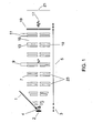
- FIG. 1 Schematic of an ion mobility drift cell with alternating high and low electrical field regions.
- FIG. 2 Illustration of field lines in a short typical cell with three electrode pairs simulated by SIMION.
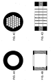
- FIG. 4 Comparison of a single-hole aperture and multi-hole aperture; 4A: single aperture; 4B: cross sectional view of 4A; 4C multi-aperture; 4D cross sectional view of 4C.
- FIG. 5 Schematic illustration of a circular array of 50 ⁇ m diameter holes spaced by 25 ⁇ m.
- FIG. 6 SIMION simulations showing the focusing effect of the multi-hole aperture, 6A; and the resulting equipotential electric field lines, 6B.
- 6C shows a crosssection of the SIMION simulation of the configuration which has an addition of a third biasable element made up of electrically connected small cones.
- FIG. 7 Schematics showing progressive change of the distribution of the holes to change the beam profile from a circular spot to a narrow horizontal rectangle; 7A, front view; 7B, cross-sectional view.
- FIG. 8 Schematic showing reduction of the ion beam size from 8 mm 2 open area multi-hole aperture (corresponding to the usual 1/8 inch diameter-opening) to the 0.07 mm 2 multi hole-aperture (corresponding to the usual 300 ⁇ m diameter-opening) ; 8A, front view; 8B, cross-sectional view.
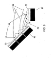
- FIG. 9 Induction of a surface dipole on a highly polarizable material using a conical (left) or flat film-coated orifice.
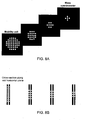
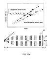
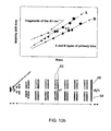
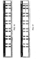
- FIG. 10 Two-dimensional representation of the mass-mobility spectrum of a complex mixture of molecular ions (top) and corresponding instrumental platform (below): 10A, the fragmentation occurs at the end of the mobility cell; 10B, the fragmentation is performed in the middle of the mobility cell.
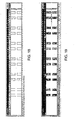
- FIG. 11 Schematic of a mobility cell in an atmospheric interface mass spectrometer.
- FIG. 12 Simulation showing two types of ions (black and gray) moving in a 20-electrode, 3 cm-long cell under 1200 V and a 2 Torr He pressure.
- FIG. 13 Same simulation as described in FIG. 12 at time of ion arrival at end of drift tube; ion transmission is about 29%. This screen copy is taken when the ions have arrived.
- FIG. 14 Same simulation as described in FIG. 12 with potential modified between electrodes in last three pairs; ion transmissionis about 56%.
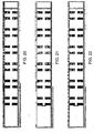
- FIG. 15 Simulation showing two types of ions (black and gray) moving in a 12-electrode, 3 cm-long cell under 1200 V and a 2 torr He pressure.
- FIG. 16 Same simulation as described in FIG. 15 at time of ion arrival at end of drift tube; ion transmission is about 56%.
- FIG. 17 Same cell characteristics and simulation parameters as described in FIG. 16 except that a higher overall axial voltage is applied (1800 V instead of 1200 V).
- FIG. 18 Same simulation as described in FIG. 17 at time of ion arrival at end of drift tube; ion transmission is about 71%.
- FIG. 19 Same cell characteristics and simulation parameters as described in FIG. 15 except that a 100 V-RF voltage is superimposed to the DC axial voltage (1200 V).
- FIG. 20 Same simulation as described in FIG. 19 at time of ion arrival at end of drift tube; ion transmission is about 36%.
- FIG. 21 Same cell electrode characteristics and configuration as described in FIG. 15 monitoring the transmission of SIMS ions; ion transmission is about 42%.
- FIG. 22 Same cell characteristics and simulation parameters as described in FIG. 21 except for the higher beam energy (1 eV instead of 0.1 eV) and field in the ionization interface (50 V/cm); Ion transmission is about 9%
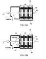
- FIG. 23 Schematic of mobility cell breakdown voltage and transmission testing setup; 23A, wide opening at the skimmer; 23B, narrow orifice and side openings.
- FIG. 24 Copy of an AutoCAD drawing of the cell mechanical design.
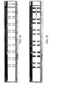
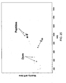
- FIG. 25 A typical 2D mass-mobility spectrum obtained using the described mobility cell of FIG. 24 .
- FIG. 26 . 26A combination of a special mobility interface tube with the differential pumping including a conical skimmer; 26B, detailed view of the interface drift tube.
- FIG. 27 Schematic of the setup for bipolar mass spectrometry of aerosol particles. Schematic of tandem arrangement for injecting either mobility separated ions, mobility separated ionized particles, or neutral particles into the ionization region between to mobility TOFMS apparatus for separating and measuring mobility and fragmented ions or ions desorbed from the injected particles.
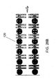
- FIG. 28. 28A Schematic view of RF interface between mobility cell and mass spectrometer; 28B: Cross-sectional view of one RF interface region.
- aperture means "hole” or "orifice”.
- Electrode triad is a distinct group or cluster of three electrodes.
- intra-electrode gap refers to the gap between two electrodes of an electrode pair.
- inter-electrode gap refers to the gap between electrode pairs.
- MALDI matrix assisted laser desorption ionization
- SIMS secondary ion mass spectrometry
- TOF time-of-flight mass spectrometer
- oTOF time-of-flight mass spectrometer configured orthogonally to the analytical axis of a preceding instrumental platform such as, for example, the separation axis of an ion mobility cell.
- IM-oTOFMS refers to a combination of an ion mobility spectrometer with an orthogonal time of flight mass spectrometer.
- the cooled ions exit through a small aperture into a differentially pumped low pressure region within the mass spectrometer.
- the ion beam inside the drift cell has to be focused.
- alternating regions of high and low field are used to provide the focusing ( FIG. 1 ) along the entire mobility cell which is filled with gas at a pressure of between 1 and several hundred Torr. Most commonly this gas will be helium, although other gases or gas mixtures may be used.
- the alternating high and low field regions are created by varying the distance between electrodes, while the bias voltage between all electrodes is the same.
- the small gaps (7) and the large gaps (15) between electrode pairs may be biased by independent power supplies to any desired ratio limited only by the onset of electrical discharge through the gas along the central axis of the mobility cell.
- the width of the small gap (7) is chosen so that it is comparable or less, preferably substantially less, than the mean free path of electron motion in the gas at a particular operating pressure. By so doing, high voltages in these gaps can be applied without causing an electrical discharge along the axis of the mobility cell.
- a pulsed laser or particle beam or other ionizing radiation (1) is used to desorb ions and neutrals from a surface (2) (which may be a MALDI matrix preparations) so that ions and neutrals are injected into the initial ion transport region (3).
- the ions may be derived from a MALDI or SIMS desorption process, among others. Desorbed ions then rapidly (within a few hundreds of nanoseconds) enter the ion mobility drift cell (5).
- a neutral post desorption ionization source (4) which is most commonly an energetic photon source which may be a laser is timed to intersect these cooled neutrals as they migrate away from the surface (2).
- the post ionized neutrals will then enter the mobility cell (5) some several microseconds after the directly desorbed ions.
- High field regions are created between the sets of two very closely spaced electrodes rings ("paired" electrodes), one of which is illustrated by (7).
- paired electrodes very closely spaced electrodes rings
- several of the small gaps, for example (9) and (11) can be configured so that additional voltage pulses can be applied to achieve collision-induced dissociation of mobility separated ions within these gaps.
- Dissociation of mobility separated ions can also be achieved by impinging ionizing radiation (10) at a specified time during which a mobility separated ion enters an intra-electrode gap (13).
- This ionizing radiation may be a laser which is focused through a transparent window into the intra-electrode gap (13).
- the gap (13) between individual electrodes in an electrode pair is a high field region, while the gap (15) between electrode pairs (23) is a low field region.
- FIG. 2 An example of this field penetration for different inter-electrode spacings is shown in FIG. 2 (a SIMION simulation).
- the relevant parameters are as follows.
- the entrance field is 100 V/cm.
- the distance between the target and first electrode is 5 mm.
- the thickness of the electrodes is 200 ⁇ m and the opening diameter 2.2 mm.
- the intra-pair gap is 1.6 mm and inter-pair gap 4 mm.
- 100 V is applied between each electrode, creating fields of 625 V/cm inside a pair and 250 V/cm between pairs.
- Field penetration can be seen in front of the entrance region which focuses the ions toward the cell separation axis.
- the exit pair is also shown: the electrodes are thinner (100 ⁇ m) and only 100 ⁇ m apart.
- the gap between this exit pair and the precedent pair is also smaller (0.5 mm).
- 100 V is also applied between the exit and precedent pairs (200 V/cm) and inside the exit pair electrodes (10 kV/cm).
- the exit electrode pair prevents the defocusing at its entrance.
- the beam is further focused to enter the low pressure analyzer region through the 300 ⁇ m aperture.
- the equipotential electric field lines help to visualize the focusing field effect.
- Inside the small gaps there is an opposite component that tends to defocus ions, but the field is stronger, and, therefore, the ions move much faster and spend less time in this region compared to the large gaps.
- the net effect consists in preventing ions from being lost on the electrodes and in their concentration close to the cell axis, and finally, their transmission through the skimmer orifice.
- Additional focusing of ions into the orifice can be achieved by a special configuration of a few last electrodes.
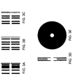
- the thicker electrodes can be used at the end of the cell ( FIG. 3A ).
- decreasing diameter of electrodes is used ( FIG. 3B ).
- FIGS. 2 and 3C it is possible to use a pair of electrodes with a very narrow gap and small opening comparable with the exit orifice ( FIGS. 2 and 3C ).
- the "opening" is the space between the upper and lower electrodes and should be distinguished from both the inter- and intra-electrode gaps. Strong field penetration from this gap is likely to provide good focusing of the ion beam into the mass spectrometer.
- FIG. 3D A way to produce such doublet electrodes is shown in FIG. 3D .
- These doublets can be made by bonding metal discs to ceramic and laser cutting aligned holes in both pieces of metal.
- the discs can be made out of polyimide which is metalized on both sides. Typical dimensions of the hole size might be 0.5 mm and the spacing of the doublet is also 0.5 mm.
- FIG. 3E is a front view of the doublet electrode of FIG. 3D .
- approximately three times the number of these doublets in the same linear distance as shown in the SIMION simulation of FIG. 2 could be used. It is possible to raise the voltage several times higher as compared to the more widely spaced geometry of the larger gapped structures shown in FIGS. 1 and 2 without increasing the fragmentation of the molecular ions.
- the distance between two adjacent electrodes should be smaller or comparable to the mean free path of electrons at the cell gas pressure in order to prevent the development of the electron avalanche and the glow discharge in the high field region.
- the risk of starting a discharge through the channel will be eliminated since high energy electrons formed inside the high field region are slowed down in the low field regions and are unlikely to propagate the discharge.
- Low field regions are created between the paired electrodes by positioning the paired electrodes so that there is a significantly larger space between each pair (inter-electrode gap) than that between the electrode elements of each pair (intra-electrode gap).
- narrower gaps in the instrument of FIG. 1 accomplishes several things.
- the field strength which can be applied without breakdown at higher pressures increases.
- the mean free path of the gas becomes shorter as the pressure increases and collisions become more frequent.
- the small gap width must be matched to be about of the mean free path for electron-atom collision or breakdown will occur at a lower voltage than that desired.
- the hole sizes must also decrease so that the field penetration from the narrow gap between electrodes into the large gap (as shown in FIG. 2 ) can be contained to a region not much larger than the hole diameter. This prevents discharge, but still allows some field penetration so that the ions traversing the large (low field) gap will experience a focusing field as they approach the first electrode of the high field small gap doublet (electrode pair).
- the first several sets of electrodes have a small but increasing outside diameter so that it is possible to position the entrance of the cell very close to the sample (about 4 mm) and still allow for the laser or ion beam to be incident at a steep angle necessary to obtain good focusing.
- This small physical profile of the mobility cell is especially useful in applications where a miniaturized approach to the mobility and/or mass spectrometry is required.
- orthogonal MALDI electrospray mass spectral analysis
- the ions are desorbed into several tens of mTorr pressure and cooled with quadrupoles which are operated near electrical ground reference.
- the cooled ions are then injected into the orthogonal extraction plates in an orthogonal time-of-flight mass spectrometer (OTOF) where they are given up to a few kilovolts of energy from the high voltage pulse applied to the extractor plates.
- OTOF orthogonal time-of-flight mass spectrometer
- the ions then disperse in either a linear or reflector time of flight section. They are given their final high kinetic energy by an attractive electrical potential which is applied to the front of the detector.
- This potential is maintained at as high an attractive electrical potential as possible to give the ions maximum acceleration energy to enable the best possible detection of large biomolecular ions.
- This high electrical potential requires that the output of the detector be either optically or electrically decoupled from the amplification and timing circuitry which is operated at ground. This decoupling limits the high voltage applied to the front of the detector to around 10-20 keV or less.
- the instant mobility cell will allow the MALDI ions to be formed near ground potential and then they can climb (or descend) within the mobility cell to high voltages such as -10 keV before they enter the mass spectrometer.
- the mass spectrometer must then be floated to this high potential; however, if the sign of the charge of the bio-ion can be changed in the orthogonal extraction region of the time-of-flight mass spectrometer (TOF) from positive to negative, the ion detector in the TOF can be operated with its output at ground. Changing the charge may be accomplished by a low energy monochromatized electron beam tuned to electron attachment resonances of the ion and subsequent neutral species after the attachment of two electrons.
- This electron beam can alternatively be used to fragment the ions within the orthogonal extraction region into positive and negative fragments which can then be accelerated into the mass spectrometer using appropriate biasing.
- the charge may be changed by chemical ionization reactions which would change the charge from positive to negative while the ions are in the region between the orthogonal plates.
- the charge can be altered by photo-affinity labeling the analyte with some negative ion adduct or electron attachment reactions.
- the detector does not have to be operated at ground potential but can be biased to between 10-20 keV so that the kinetic energy of the large bio-ions would for example approach 30 keV upon reaching the detector.
- This charge conversion in the orthogonal plates not only improves the detection efficiency, but it also may improve specificity and reduce clutter by ionizing only certain types of molecules which have electronegative groups such as sulfohydrils or phosphate.
- Another well known example is the energy specific (resonant) attachment of electrons to small molecules such as explosives which contain nitro groups or larger biomolecular ions.
- the ability of the instant mobility cell to withstand high voltages without causing gas discharge makes it easier to time voltage sequences so that the entire electrical potential of the IMS and TOF spectrometers can be raised or lowered linearly or non-linearly during the time that the desorbed ions are inside the mobility cell. In this way the electrical potential of the ions exiting the mobility cell will be increased relative to the electrical potential of the ion detector in the TOF. This facilitates detection larger and larger ions such as for example proteins.
- FIGS. 4A-D illustrate the general concept of using multi-hole apertures versus a single hole aperture.
- FIG. 4A shows a single aperture and FIG. 4B demonstrates the cross sectional view.
- FIG 4C shows a multi-aperture exit and FIG. 4D .
- FIG. 5 shows an example of an arrangement of holes in a circular array comprising a web area (25). Such a circular array will ideally have about 4033 holes and will be used to replace the 1/8 inch diameter single-hole aperture.
- the same opening area of 8 mm 2 will be covered by a 4033 holes-circular array of 5.37 mm diameter.
- the holes are 50 ⁇ m diameter spaced by 25 ⁇ m.
- the 1/8 inch diameter single hole aperture is replaced by a 4033 holes-circular array of 5.37 mm diameter; both having the same opening area of 8 mm 2 .
- the 300 ⁇ m exit aperture will be replaced by an aperture with 36 50 ⁇ m-holes distributed on an array of 508 ⁇ m diameter. While specific examples in terms of dimensions have been disclosed above, it is understood by those of skill in the art that other variations in the multi-aperture embodiment are within the scope of the invention.
- the field created between a pair of multi-hole apertures separated by 25 ⁇ m focuses the cooled ions.
- the array As the diameter of the array of holes is larger than the single-hole diameter, the array "intersects" with a larger part of the cooled ion beam than a single hole-aperture. With the focusing effect of the holes, the transmission is enhanced.
- the multi-hole aperture also reduces the space charging. Since the mean free path of the mobility gas (about 1 mm in 1 Torr He) is larger than the hole diameter, the multi-hole aperture likely intercepts more molecules than a single-hole aperture having the same opening area. In other words, the multi-hole aperture helps differential pumping.
- the transmission will be significantly enhanced by the use of a multi-hole aperture instead of single-hole aperture.
- the field penetration between holes focuses the ions.
- the electrodes are 5 ⁇ m thick, the insulating material (e.g. polyimide) is 25 ⁇ m thick.
- the cooled ions have initial energy in the mV range and are accelerated by 500 mV in front of the first multi-hole aperture. Between the two multi-hole apertures, a field of 24 V/mm is applied.
- FIG. 6C shows a cross-section of the SIMION simulation which tracks ions into a multiaperture paired exit electrode to which a third biasable electrode has been added.
- This third electrode is situated above the web area (25) which is the solid electrode material and insulator remaining on the face of the aperture between the open holes.
- the biasable electrode By so positioning the biasable electrode, almost all ions approaching this web area are deflected by the combined effects of the field penetration and the gas flow into one or the several open holes bordering the specific portion of the web which the mobility ion has approached.
- a fourth such electrode could be added to the back side of the multiaperture paired electrode.
- the electrodes may not need to be biasable, but could comprise a thin dielectric coating which would charge to produce a dipole field repulsion of the mobility ions as they approached the web area (25).
- the electrode could comprise a piezoelectric thin film (which may also be coated with a thin dielectric) which could be biased to produce this dipole field.
- These multiaperture paired electrodes is not restricted exclusively to improving the performance of the exit aperture - particularly if the third and fourth electrodes shown in FIG. 6C are added to reduce or eliminate any loss of mobility ions on the web area (25). It is then possible to use these multiaperture paired electrodes as the electrodes for the mobility cell region (5) itself. If the size of the array is gradually reduced as the ions are transported toward the cell exit (keeping the size of the hole and their arrangement the same), the focusing effect of the multiaperture paired structure can then be used to optimize the transmission.
- FIG. 8 schematically shows such a usage (the figure is not drawn to scale and shows doublet electrodes only although it is understood that triplet and quadruplet structures such as shown in FIG.
- 6C can also be used for each element).
- the progressive reduction of the mobility ion beam size from a 8 mm 2 open area multi-hole aperture (corresponding to the usual 1/8 inch diameter-opening) to a 0.07 mm 2 multi hole-aperture (corresponding to the usual 300 ⁇ m diameter-opening) is schematically illustrated.
- the diameter of the circular array will be reduced from 5.37 mm to 508 ⁇ m.
- the focusing effect shown in FIG. 6 and the gradual reduction of the open area will minimize the ion loss as the cooled ions are transported from the mobility cell to the high vacuum region of the o-TOF MS.
- Another way to improve the transmission into the mass spectrometer is to use the focusing effect of the multi-hole electrodes by gradually changing the distribution of the holes to change the beam profile from its initial circular spot to a narrow horizontal rectangle ( FIG. 7 ; not to scale).
- a gradual change of the ion beam profile from circular to horizontal slit-like shape produces a more focused and parallel beam in the orthogonal TOF MS extraction region.
- Being able to change the mobility ion beam shape before the ions exit into high vacuum gives many practical advantages.
- FIG. 9 shows two possible approaches that involve either a flat (27) or conical (30) surface, coated with a piezoelectric thin film (33) around an orifice (42). Negative charges which initially were formed on the film surface close to the conductor should be totally compensated by corresponding positive charges on the conductor surface so they are not shown.
- a piezoelectric thin film e.g. PZT (lead zirconate titanate or Pb(Zr x Ti (1-x) )O 3
- FIG. 9 shows two possible approaches that involve either a flat (27) or conical (30) surface, coated with a piezoelectric thin film (33) around an orifice (42). Negative charges which initially were formed on the film surface close to the conductor should be totally compensated by corresponding positive charges on the conductor surface so they are not shown.
- the CID gap (45) is at the end of the drift cell near the exit electrode pair (48). Cooled ions (51) exit the cell.
- the CID gap (53) is in the middle of the mobility cell.
- This configurations also has an exit electrode pair (56), with cooled ions (59) exiting the cell. All other components are as described for FIG. 1 .
- the voltage between selected adjacent electrodes can be increased to a level where high kinetic energy collisions start to fragment the analyte ions.
- very high voltages can be applied without inducing electrical discharge in the carrier gas because of the mean free path length of the carrier gas is longer than the distance between electrodes and this represents considerable improvement over other such dissociation devices which have been previously propose in the prior art.
- the dissociating voltages can be applied either in DC mode so that all ions going through the region undergo fragmentation, or by applying a short voltage pulse, or laser pulse, or glow discharge pulse so that only ions present in the gap at the time of pulse application are decomposed. If the ions have been previously pre-separated in time by their shapes, only ions with a certain collision cross section will be fragmented. When they are detected by the mass analyzer, they fall onto different "trend lines" in the two-dimensional mass-mobility spectrum ( FIG. 10A ), thereby improving overall resolution. These lines are usually formed by molecules of similar shape and structure but different mass (such as peptides, or lipids).
- fragments are allowed to further travel through the remainder of the cell (for example, if the CID (53) is performed in the middle of the cell), they are further resolved. As a result, fragments now align along their own separate trend line ( FIG. 10B ). If an additional (either DC or pulsed) CID stage is implemented at the end of the mobility cell, it is possible to perform further selective fragmentation of these fragments. These selective fragmentations, in effect, produce an instantaneous multiple MS setup. The feasibility of further MS n stages is only limited by the necessity of additional stages which may ultimately limit either mobility resolution or ion transmission into the mass spectrometer.
- the vacuum enclosure of the mobility cell can be easily achieved by placing viton o-rings between electrodes and compressing the whole structure. Since the vacuum requirement for this section is not very strict (the pressure is in the Torr range), little compression is enough to maintain the purity of the mobility carrier gas.
- optically transparent glass can be used to allow introduction of photon beams for promoting ionization or ion (or electron) molecule reactions.
- Ion mobility drift tube in the combination Ion Mobility and High Pressure MALDI Mass spectrometry; 2) Ion mobility drift tube in the combination of Ion mobility and Secondary Ion Mass spectrometry; 3) Pressure interface for the high pressure sources, such as Electrospray Ionization and Atmospheric Pressure MALDI.
- the difference between the systems is the pressure in the region where the ions are formed.
- ions are generated at similar pressures to that of the mobility cell (a few Torr).
- SIMS ions are formed in higher vacuum (a few mTorr) and travel against the flow of the carrier gas as they enter the drift cell.
- the pressure in the source region is higher (up to 1 atm). In the latter case an additional differential pumping of the cell is required. If the influence of the gas fluxes or the ion diffusion can be minimized or used for the benefit of the high transmission, the same basic design can be applied to all this variety of applications.
- FIG. 14 shows the same ion motion conditions as described in FIG, 12 with modified (field in the ionization interface set at 100 V/cm).
- the cell is slightly different from the cell described in FIG. 12 .
- the gap between paired electrodes of the three last pairs is gradually reduced as well as their inner diameter.
- the potential difference in the last three pairs is twice the potential difference in the other pairs. This snapshot is taken when the ions have arrived.
- the overall transmission is about 55%. Ions are lost at the three last electrode pairs.
- This snapshot ( FIG. 15 ) of the simulation is taken before the ions reach the exit electrode pair. Few ions are discharged on the first ring electrode. The estimated resolution is 13 for the light ions and 18 for the heavy ions. In FIG. 16 , the conditions are the same as those of FIG. 15 , and the snapshot is taken when the ions have arrived. The overall transmission is about 55%. Few ions are lost at the first ring but most at the exit electrode pair. In comparison with the previous design, the distance between two last pairs is limited to 0.5 mm to reduce the ion diffusion and beam divergence. For the same reason, the distance between exit electrodes is 100 ⁇ m. The resolving power is similar to the previous case. Four ions out of initial 200 are lost discharged on the entrance electrode.
- the instrumental platform is shown in FIG. 23 .
- Two modifications of the cell were tested.
- a short (0.7") cell was pumped from the back side through the wide (2.2 mm diameter) opening.
- the air pressure was maintained around 2 Torr.
- the vacuum insulation was provided by the use of o-rings (80) of different thickness, which also served as variable spacers.
- the corona discharge created by applying high voltage between the sharp wire tip (83) and the entrance electrode (87) served as an ion source.
- the electrodes were connected by a resistor chain (90) to provide necessary voltage drops. This setup allows estimation of the maximum voltages that can be applied between the electrodes and across the entire cell, and estimation of the ion losses on the electrodes.
- FIG. 24 shows the experimental setup with sample (97), mobility cell (100), and mass spectrometer (104). A test cell with the following parameters was tested.
- the new design allows one to apply voltages that are impossible in a regular periodic or linear mobility cell due to the possibility of a discharge.
- a certain level typically about 2000 V
- the mobility resolution improvements become negligible while the collision induced dissociation of ions increases.
- the increase in the cell gas pressure allows avoidance of ion fragmentation at higher fields.
- the requirements for the high vacuum in the mass analyzer section limit the cell pressure to the range below 10 Torr. This pressure limitation can be removed by using higher pumping speed in the mass spectrometer which would allow the mobility cell to be operated at even higher pressures and voltages.
- FIG. 26A demonstrates the combination of a special mobility interface tube with the differential pumping including a conical skimmer.
- a sample introduction (108) at the entrance of the mobility cell (112).
- ions Upon exiting the mobility cell (112), ions enter a differential pumping interface (124) through an orifice (116) located between an interface drift tube (120) and the mobility cell (112). Additional focusing to improve throughput is accomplished by the use of the interface drift tube (120).
- FIG. 26B is an expanded view of the interface drift tube (120).
- the mass spectrometer can ideally be one of the configurations using a position sensitive detector as described in the following: U.S. Patent 6,683,299 to Fuhrer et al. ; in copending application 10/155,291 to Fuhrer et al. filed on October 20, 2003 ; and in the U.S. application of Fuhrer et al. filed on October 18, 2003 and having attorney docket no. HO-P02142US3 (application number not yet assigned) which includes the ability to read and keep separate the ion output of multiple IMS channels using only one mass spectrometer.
- the use of an extra drift tube placed right after the main mobility cell is based on the necessity to provide a smoother pressure drop after the skimmer orifice, and to form a high quality molecular beam with low divergence and ion energy spread.
- these two parameters achieve high resolution and sensitivity of the mass spectrometer.
- the channel diameter in the interface is larger than that of the mobility cell, and the applied field is lower due to lower pressure.
- the focusing of ions is achieved using the same method as in the main mobility - by varying the distances between electrodes. If the voltage applied to the gaps between the electrodes is the same, the field is stronger in the small gaps, and there is a field penetration into the large gaps, which produces the focusing effect.
- the experimental data shows that there is no or very little ion loss in the interface.
- the mobility resolution after the interface is only about 10% lower than the resolution right after the mobility cell.
- the pressure drop in the interface allowed operating at 2.5x higher pressure and applying 2x higher voltage across the mobility cell. This achieves high resolution using a very short (5") drift cell.
- FIG. 27 schematically illustrates the use of a mobility cell or some other gas transport device (158) to inject ionized or non-ionized particles or molecules (156), i.e., neutral species, into the entrance region between two opposing IM-oTOFMS spectrometers (148 and 152), the region between the two opposing IM-oTOFMS comprising two opposing mobility cells (140) and (144).
- the two mobility drift cells are configured in a substantially horizontally opposed manner, i.e., having separation axes configured 180° or approximately 180° from one another.
- the ion or neutral species may be subjected to a fragmentation source.
- One of the oTOFMS operates in negative mode, while the other operates in positive mode.
- analyte (156) is injected into this region, it is irradiated with ionizing radiation (160). Both positive and negative ions are created and are transported by the opposing fields into one or the other of the appropriately biased spectrometers.
- the bias of the entrance to the spectrometers can be controlled by a computer sequence so that the region between the entrance to the mobility cells is field free.
- Analyte (156) can then drift (either as ions or as neutrals) along with the gas flow which is orthogonal to the axis of the mobility cells.
- extraction pulses are simultaneously or sequentially applied to the face of the mobility cells so that ions are extracted into the respective mobility cells according to the ion polarity.
- ionizing radiation can be applied to convert the gas transported neutrals into ions and these post ionized neutrals would also enter the two mobility cells. All of the post-ionization features described previously as referenced to FIG. 1 would apply for both the negative and positive mobility spectrometers.
- Fig 1 and Fig 27 illustrate a single channel of mobility in each polarity IMS, it is understood that the mobility cells can also be multi-channeled mobility cells as described in this application and in the following: U.S. Patent 6,683,299 to Fuhrer et al. ; in copending application 10/155,291 to Fuhrer et al. filed on October 20, 2003 ; and in the U.S. application of Fuhrer et al.
- each electrode from flexible circuit board copper-kapton-copper material. Desired hole arrays would either be punched or laser drilled into a cut coupon of the material so that the electrical isolation of the front and back copper was maintained. Electrical connection to the front and back isolated copper electrodes could be formed by known circuit board etching techniques. The coupons could then be aligned and sandwiched together in a mechanical jig and mold into which epoxy would be poured and cured. The high vacuum epoxy would make a suitable vacuum seal and the intimate electrical contact of the back of one coupon to the face of the next would eliminate any of the exposed web areas and would thus form small individual ion mobility columns each of which could be used to resolve its own stream of ions.
- the electrical biasing of each element would be easily done by a combination of power supplies and resistors applied to the leads which would emerge from the hardened epoxy housing.
- the interface region (120) of FIGS. (26A and 26B ) can also be made by this technique.
- the interface region (120) can also be located outside of the vacuum housing containing the skimmer and differential pumping capability.
- An ideal multibore IMS cell would feed each of its channels directly into a multihole skimmer and thence into the oTOFMS or it could also be fed through an RF mulitpole cooling apparatus as shown in FIG. 28 which serves to keep the output of each channel spatially separated and substantially parallel as each goes into an ion detection device which may be a oTOFMS equipped with a position sensitive detector.
- each of the two rectangular envelopes (one for each RF stage in FIG. 28 ) and the sixteen rods in each stage are electrically connected to a common DC potential and so have the same DC potential for acceleration of ions coming into each stage.
- the rods additionally are supplied by RF-voltages of opposite phases and the same amplitude (+U sin ⁇ t and -U sin ⁇ t). Ions are focused to positions around the points of zero RF-field.
- a particularly useful and powerful embodiment of this device is for the case when ions have been separated on the basis of their charge to volume ratio by an IMS cell prior to their entering the RF interface.
- the amplitude or frequency of the RF field can be continuously optimized to maximize the transmission of the particular charge to volume ratio which is present at any particular time relative to the start of the IMS separation. This is very useful for MALDI-IMS experiments in which the singly ionized charge state is predominant.
- IMS of familial classes ofbiomolecules have been found to have a predictable relationship between the charge to volume and the charge to mass of each ion in the familial class.
- the RF field would have optimal characteristics for low m/z values at the start of the IM separation and very different field characteristics as the larger m/z ions eluted from the IM cell at longer mobility drift times.
- An approximately linear increase of m/z values along a familial trend line occurs. It is a reasonable approximation to increase the amplitude of the RF-voltage which is applied to the rods to be proportional to the square root of the time measured relative to a zero time when the initiation of the ionization event occurs.
- the coefficient of proportionality is the slope of the familial trend line.
- Such a time changing RF-field thus synchronized to the elution of ions at the end of the mobility cell would allow to record small ions without defocusing and losing them due to possible instability of their motion for large RF-fields necessary for the focusing and transport of larger ions. Also it would allow the effective focusing of ions of large masses for essentially the same width ion beams for ions of all masses. Since multi-charged ions would be focused even better than for the singly charged ions such an approach will focus all ions well below 1 mm diameter ion beams as the corresponding simulations show.
- the length and the number of the sections and the DC voltages applied to them should be found by computer simulation for providing enough time for desired ion focusing without losing of their separation received before in mobility cell and without decomposing of the ions. Any broadening of the mobility resolution because of the increased residence time of ions in the RF assembly could be almost completely removed by numerical devonvolution of the mobility resolved spectra after first determining-- either experimentally or theoretically - the residence time as a function of mass of the ions within the RF assembly.
- An RF-field ion focusing gives ions additional energy of ion motion in the plane orthogonal to axis being equal to the ion thermal energy. See, for example, Raznikov, et al RCM V 15, 1912-1921 (2001 ). If the axial velocity of ions is small in comparison with average thermal velocity of helium ( ⁇ 1300m/sec) then the thermal energy of ions corresponds to the room temperature and it is about 0.013 eV per 1 degree of freedom. Of interest here is the degree of freedom which lies in the plane of the channels of our ion guide orthogonal to the direction of ion motion which due to RF-field contribution wherein we would have about 0.026 eV energy.
- the divergence angle on average would be about 0.03 rad.
- the ion beams would, on average, be 6 mm wide after traveling 10 cm. The distance between ion beams of 6 mm and the width of recording plate 50 mm would be enough for recording the output of eight individual channels.
Landscapes
- Chemical & Material Sciences (AREA)
- Physics & Mathematics (AREA)
- Spectroscopy & Molecular Physics (AREA)
- Chemical Kinetics & Catalysis (AREA)
- Analytical Chemistry (AREA)
- Health & Medical Sciences (AREA)
- Life Sciences & Earth Sciences (AREA)
- Electrochemistry (AREA)
- Molecular Biology (AREA)
- Biochemistry (AREA)
- General Health & Medical Sciences (AREA)
- General Physics & Mathematics (AREA)
- Immunology (AREA)
- Pathology (AREA)
- Other Investigation Or Analysis Of Materials By Electrical Means (AREA)
- Analysing Materials By The Use Of Radiation (AREA)
Claims (37)
- Vorrichtung, umfassend:eine Ionenquelle undeine erste Ionenmobilitäts-Driftzelle, wobei die erste Ionenmobilitäts-Driftzelle einen Eingang hat, der an die Ionenquelle fluidgekoppelt ist, dadurch gekennzeichnet, dassdie erste Ionenmobilitäts-Driftzelle mindestens zwei Elektrodenpaare (23), die einen Intra-Elektrodenspalt (13) zwischen einzelnen Elektroden eines Paars haben, der kleiner als ein Inter-Elektrodenspalt (15) zwischen Elektrodenpaaren (23) ist, und einen Ausgang umfasst.
- Vorrichtung nach Anspruch 1, wobei Elektroden nahe des Ausgangs der Ionenmobilitätszelle eine größere Dicke haben als Elektroden (23), die weiter entfernt von dem Ausgang der Ionenmobilitätszelle sind.
- Vorrichtung nach Anspruch 1, wobei die Elektroden (19) nahe des Ausgangs der Ionenmobilitätszelle einen geringeren Durchmesser haben als Elektroden (23), die weiter entfernt von dem Ausgang der Ionenmobilitätszelle sind.
- Vorrichtung nach Anspruch 1, wobei die Elektroden (19) nahe des Ausgang der Ionenmobilitäts-Driftzelle eine oder mehrere Blenden haben, die bezüglich der Abmessung vergleichbar mit den Abmessungen des Ausgangs sind.
- Vorrichtung nach Anspruch 1, wobei eines oder mehrere Elektrodenpaare nahe des Eingangs der Ionenmobilitätszelle einen geringeren Außendurchmesser haben als ein oder mehrere Elektrodenpaare (23), die weiter entfernt von dem Eingang sind.
- Vorrichtung nach Anspruch 5, wobei die ersten mehreren Sätze von Elektroden nahe des Eingangs der Ionenmobilitätszelle einen zunehmenden Außendurchmesser in der Richtung des Ausgangs haben.
- Vorrichtung nach Anspruch 1, weiterhin eine HF-Spannung und eine DC-Elektrodenspannung umfassend, wobei die HF-Spannung auf die DC-Elektrodenspannung superpositioniert ist.
- Vorrichtung nach Anspruch 1, weiterhin ein Flugzeit-Massenspektrometer umfassend, das an den Ausgang der Mobilitäts-Driftzelle durch einen orthogonalen Extraktor und einen monochromatisierten, niederenergetischen Elektronenstrahl, der an den orthogonalen Extraktor gekoppelt ist, fluidgekoppelt ist.
- Vorrichtung nach Anspruch 1, wobei der Ausgang eine Vielzahl von Blenden umfasst.
- Vorrichtung nach Anspruch 9, wobei die Vielzahl von Blenden in einem 4033 ringförmigen Array von Blenden beinhaltet ist, wobei das Array einen Durchmesser von 5,37 mm und eine Gesamtblendenfläche von 8 mm2 hat.
- Vorrichtung nach Anspruch 1, wobei ein oder mehrere Elektroden in der Driftzelle eine Vielzahl von Blenden haben.
- Vorrichtung nach Anspruch 11, wobei sich die Verteilung von Blenden in den Elektroden von dem Eingang zu dem Ausgang verändert.
- Vorrichtung nach Anspruch 12, wobei sich die Verteilung von Blenden von einer ringförmigen Verteilung zu einer horizontalen rechtecksförmigen Verteilung ändert.
- Vorrichtung nach Anspruch 1, wobei der Ausgang zumindest teilweise mit einer dünnen Isolierschicht beschichtet ist.
- Vorrichtung nach Anspruch 14, wobei die Isolierschicht eine piezoelektrische Schicht (33) umfasst.
- Vorrichtung nach Anspruch 1, wobei ein oder mehrere Elektroden piezoelektrische Dünnschichten umfassen.
- Vorrichtung nach Anspruch 1, wobei die erste Mobilitäts-Driftzelle eine oder mehrere kollisionsinduzierte Zersetzungsregionen (45, 53) innerhalb von ihr hat.
- Vorrichtung nach Anspruch 17, wobei die kollisionsinduzierte Zersetzungsregion (45) nahe des Ausgangs der Mobilitäts-Driftzelle platziert ist.
- Vorrichtung nach Anspruch 17, wobei die kollisionsinduzierte Zersetzungsregion (53) nahe am Zentrum der Mobilitäts-Driftzelle platziert ist.
- Vorrichtung nach Anspruch 1, wobei die Ionenmobilitäts-Driftzelle weiterhin mindestens eine poröse Halbleiterelektrode (62) umfasst.
- Vorrichtung nach Anspruch 20, wobei sich die mindestens eine poröse Halbleiterelektrode (62) direkt hinter dem Eingang (63) befindet.
- Vorrichtung nach Anspruch 20, wobei die mindestens eine poröse Halbleiterelektrode (62) mit einer dielektrischen oder piezoelektrischen Dünnschicht beschichtet ist.
- Vorrichtung nach Anspruch 1, wobei die Ionenquelle eine MALDI-Quelle ist.
- Vorrichtung nach Anspruch 1, wobei die Ionenquelle eine sekundäre Ionenquelle ist.
- Vorrichtung nach Anspruch 1, wobei eine oder mehrere der Elektrodenpaare durch Elektrodentriaden ersetzt sind.
- Vorrichtung nach Anspruch 1, wobei mindestens eine von den Elektroden eine konische Multiblenden-Skimmerelektrode ist.
- Vorrichtung nach Anspruch 1, weiterhin umfassend:eine differenziell gepumpte Schnittstelle (124), die mit der Ionenmobilitäts-Driftzelle (112) fluidgekoppelt ist;einen konischen Skimmer (128), der mit der differenziell gepumpten Schnittstelle (124) fluidgekoppelt ist;einen Extraktor (132), der mit dem konischen Skimmer (128) fluidgekoppelt ist;ein Flugzeit-Massenspektrometer, das mit dem Extraktor (132) fluidgekoppelt ist.
- Vorrichtung nach Anspruch 1, weiterhin umfassend:eine differenziell gepumpte Schnittstelle, die mit der Ionenmobilitäts-Driftzelle fluidgekoppelt ist;einen Multilochskimmer, der mit der differenziell gepumpten Schnittstelle fluidgekoppelt ist;einen Extraktor, der mit dem Multilochskimmer fluidgekoppelt ist; undein Flugzeit-Massenspektrometer, das mit dem Extraktor fluidgekoppelt ist.
- Vorrichtung nach Anspruch 1, wobei die Ionenmobilitäts-Driftzelle einen Teil eines Mehrloch-Ionenmobilitätsspektrometers ausbildet.
- Vorrichtung nach Anspruch 1, wobei mindestens eines der Elektrodenpaare aus flexiblem Kupfer-Kapton-Kupfer-Material besteht.
- Vorrichtung nach Anspruch 1, weiterhin umfassend:eine Mehrkanal-HF-Schnittstelle (175, 180), die mit der Driftzelle (165) fluidgekoppelt ist;einen Extraktor, der mit der Multikanal-HF-Schnittstelle (175, 180) fluidgekoppelt ist; undein Flugzeit-Massenspektrometer (170), das mit dem Extraktor fluidgekoppelt ist.
- Vorrichtung nach Anspruch 1, weiterhin umfassend:eine zweite Ionenmobilitäts-Driftzelle (144), die an die erste Ionenmobilitäts-Driftzelle (140) fluidgekoppelt ist, wobei die zweite Ionenmobilitäts-Driftzelle (144) Elektrodenpaare umfasst, die einen Intra-Elektrodenspalt haben, der kleiner als ein Inter-Elektrodenspalt zwischen Elektrodenpaaren ist; undeine differenziell gepumpte Schnittstelle, die mit der zweiten Ionenmobilitäts-Driftzelle (144) fluidgekoppelt ist.
- Vorrichtung nach Anspruch 32, weiterhin umfassend:einen konischen Skimmer, der mit der differenziell gepumpten Schnittstelle fluidgekoppelt ist;einen Extraktor, der mit dem konischen Skimmer fluidgekoppelt ist; undein Flugzeit-Massenspektrometer, das mit dem Extraktor fluidgekoppelt ist.
- Vorrichtung nach Anspruch 32, wobei eines oder mehrere der Elektrodenpaare der ersten Ionenmobilitäts-Driftzelle, der zweiten Ionenmobilitäts-Driftzelle oder von beiden durch Elektrodentriaden ersetzt werden.
- Vorrichtung nach Anspruch 1, weiterhin umfassend:eine zweite Ionenmobilitäts-Driftzelle (144), wobei die erste und zweite Ionenmobilitäts-Driftzelle (140, 144) im Wesentlichen horizontal gegenüberliegend zueinander sind und mit der Quelle fluidgekoppelt sind, wobei die zweite Ionenmobilitäts-Driftzelle (144) mindestens zwei Elektrodenpaare umfasst, die einen Intra-Elektrodenspalt zwischen einzelnen Elektroden eines Paares haben, der kleiner als ein Inter-Elektrodenspalt zwischen Elektrodenpaaren ist, undein erstes Massenspektrometer (152), das mit der ersten Ionenmobilitäts-Driftzelle (140) fluidgekoppelt ist und ein zweites Massenspektrometer (148), das mit der zweiten Ionenmobilitäts-Driftzelle (144) fluidgekoppelt ist.
- Vorrichtung nach Anspruch 35, weiterhin umfassend eine Fragment-Quelle, die positioniert ist, um die Ionen und neutrale Spezies, die eine oder beide der ersten und zweiten Ionenmobilitäts-Driftzellen (140, 144) betreten, zu fragmentieren.
- Vorrichtung nach Anspruch 35, wobei das erste Massenspektrometer (152), das zweite Massenspektrometer (148) oder beide Flugzeit-Massenspektrometer sind.
Applications Claiming Priority (2)
| Application Number | Priority Date | Filing Date | Title |
|---|---|---|---|
| US51282503P | 2003-10-20 | 2003-10-20 | |
| PCT/US2004/034815 WO2005043115A2 (en) | 2003-10-20 | 2004-10-20 | Ion mobility tof/maldi/ms using drift cell alternating high and low electrical field regions |
Publications (3)
| Publication Number | Publication Date |
|---|---|
| EP1676291A2 EP1676291A2 (de) | 2006-07-05 |
| EP1676291A4 EP1676291A4 (de) | 2008-05-07 |
| EP1676291B1 true EP1676291B1 (de) | 2013-04-24 |
Family
ID=34549226
Family Applications (1)
| Application Number | Title | Priority Date | Filing Date |
|---|---|---|---|
| EP04795914.3A Expired - Lifetime EP1676291B1 (de) | 2003-10-20 | 2004-10-20 | Ionenmobilitäts-tof/maldi/ms unter verwendung von driftzellen mit abwechslung von regionen mit hohem und niedrigem elektrischem feld |
Country Status (4)
| Country | Link |
|---|---|
| US (2) | US6992284B2 (de) |
| EP (1) | EP1676291B1 (de) |
| CA (1) | CA2542869A1 (de) |
| WO (1) | WO2005043115A2 (de) |
Cited By (2)
| Publication number | Priority date | Publication date | Assignee | Title |
|---|---|---|---|---|
| DE102016124900A1 (de) * | 2016-12-20 | 2018-06-21 | Bruker Daltonik Gmbh | Schaltelement in Ionenmobilitätsspektrometern |
| TWI783515B (zh) * | 2020-06-11 | 2022-11-11 | 荷蘭商Asml荷蘭公司 | 操縱器、操縱器陣列、帶電粒子工具、多束帶電粒子工具及操縱帶電粒子束之方法 |
Families Citing this family (65)
| Publication number | Priority date | Publication date | Assignee | Title |
|---|---|---|---|---|
| US7010559B2 (en) * | 2000-11-14 | 2006-03-07 | Parkervision, Inc. | Method and apparatus for a parallel correlator and applications thereof |
| US7084395B2 (en) | 2001-05-25 | 2006-08-01 | Ionwerks, Inc. | Time-of-flight mass spectrometer for monitoring of fast processes |
| US6924479B2 (en) * | 2002-01-25 | 2005-08-02 | William C. Blanchard | Ion detecting apparatus and methods |
| WO2005050159A2 (en) * | 2003-10-14 | 2005-06-02 | Washington State University Research Foundation | Ion mobility spectrometry method and apparatus |
| US7388195B2 (en) * | 2004-09-30 | 2008-06-17 | Charles Stark Draper Laboratory, Inc. | Apparatus and systems for processing samples for analysis via ion mobility spectrometry |
| ATE512458T1 (de) | 2004-12-07 | 2011-06-15 | Micromass Ltd | Massenspektrometer |
| CA2609802A1 (en) * | 2005-05-27 | 2006-12-07 | Ionwerks, Inc. | Multi-beam ion mobility time-of-flight mass spectrometer with bipolar ion extraction and zwitterion detection |
| WO2006130475A2 (en) * | 2005-05-27 | 2006-12-07 | Ionwerks, Inc. | Multi-beam ion mobility time-of-flight mass spectrometry with multi-channel data recording |
| US20070114382A1 (en) * | 2005-11-23 | 2007-05-24 | Clemmer David E | Ion mobility spectrometer |
| EP1984934A4 (de) * | 2006-02-08 | 2015-01-14 | Dh Technologies Dev Pte Ltd | Hochfrequenzionenführung |
| CN101063672A (zh) * | 2006-04-29 | 2007-10-31 | 复旦大学 | 离子阱阵列 |
| US8309913B2 (en) * | 2006-10-03 | 2012-11-13 | Academia Sinica | Angled dual-polarity mass spectrometer |
| GB0625478D0 (en) | 2006-12-20 | 2007-01-31 | Smiths Group Plc | Detection apparatus |
| EP2126957A4 (de) * | 2007-01-19 | 2012-05-30 | Mds Analytical Tech Bu Mds Inc | Vorrichtung und verfahren zum kühlen von ionen |
| WO2008136040A1 (ja) * | 2007-04-17 | 2008-11-13 | Shimadzu Corporation | 質量分析装置 |
| US20090008577A1 (en) * | 2007-07-07 | 2009-01-08 | Varian Semiconductor Equipment Associates, Inc. | Conformal Doping Using High Neutral Density Plasma Implant |
| US7709787B2 (en) * | 2007-08-24 | 2010-05-04 | The United States Of America As Represented By The Secretary Of The Department Of Commerce | Stepped electric field detector |
| JP4957805B2 (ja) * | 2007-09-18 | 2012-06-20 | 株式会社島津製作所 | Ms/ms型質量分析装置 |
| US7880137B2 (en) | 2007-12-28 | 2011-02-01 | Morpho Detection, Inc. | Electrode design for an ion spectrometer |
| CN101471222B (zh) * | 2007-12-29 | 2010-11-24 | 同方威视技术股份有限公司 | 用于离子迁移率谱仪的迁移管结构 |
| US8192523B1 (en) | 2008-02-22 | 2012-06-05 | Tsi Incorporated | Device and method for separating and increasing the concentration of charged particles in a sampled aerosol |
| US8969795B2 (en) * | 2008-10-06 | 2015-03-03 | Shimadzu Corporation | Curtain gas filter for mass- and mobility-analyzers that excludes ion-source gases and ions of high mobility |
| EP2389681B1 (de) * | 2009-01-23 | 2019-08-21 | Ionwerks, Inc. | Post-ionisierung von neutralteilchen zur otofms-ionenmobilitätsidentifikation von oberflächendesorbierten molekülen und elementen |
| US9500572B2 (en) | 2009-04-30 | 2016-11-22 | Purdue Research Foundation | Sample dispenser including an internal standard and methods of use thereof |
| US8704167B2 (en) * | 2009-04-30 | 2014-04-22 | Purdue Research Foundation | Mass spectrometry analysis of microorganisms in samples |
| US8471198B2 (en) * | 2009-05-13 | 2013-06-25 | Micromass Uk Limited | Mass spectrometer sampling cone with coating |
| WO2011017409A1 (en) * | 2009-08-05 | 2011-02-10 | Indiana University Research And Technology Corporation | Apparatus for determining masses at high pressure |
| DE102009051069A1 (de) * | 2009-10-28 | 2011-05-05 | Drägerwerk AG & Co. KGaA | Gasdetektor und Verfahren zur Überwachung der Konzentration eines Gases |
| US8541737B2 (en) * | 2009-11-30 | 2013-09-24 | Battelle Memorial Institute | System and method for collisional activation of charged particles |
| EP2507815A4 (de) * | 2009-11-30 | 2016-12-28 | Ionwerks Inc | Tof-spektrometrie und spektroskopie von oberflächen |
| US8704194B2 (en) * | 2010-04-12 | 2014-04-22 | Canon Kabushiki Kaisha | Information acquiring apparatus and information acquiring method for acquiring mass-related information |
| US8502159B2 (en) | 2010-04-29 | 2013-08-06 | Battelle Energy Alliance, Llc | Apparatuses and methods for generating electric fields |
| RU2420826C1 (ru) * | 2010-05-20 | 2011-06-10 | Учреждение Российской академии наук Институт энергетических проблем химической физики РАН Российской Федерации | Способ структурно-химического анализа органических и биоорганических соединений при разделении ионов этих соединений в сверхзвуковом газовом потоке, направленном вдоль линейной радиочастотной ловушки |
| CN102315076B (zh) * | 2010-07-05 | 2014-08-27 | 同方威视技术股份有限公司 | 离子迁移管 |
| EP2405463A1 (de) * | 2010-07-06 | 2012-01-11 | ETH Zurich | Ionenquelle für Laserablation mit Ionentrichter |
| US20120228490A1 (en) * | 2011-03-13 | 2012-09-13 | Excellims Corporation | Apparatus and method for ion mobility spectrometry and sample introduction |
| RU2468464C9 (ru) * | 2011-06-09 | 2013-05-27 | Учреждение Российской академии наук Институт энергетических проблем химической физики РАН | Способ разделения ионов органических и биоорганических соединений по приращению ионной подвижности и транспортировки этих ионов внутрь сверхзвукового газового потока |
| FR2976577B1 (fr) | 2011-06-17 | 2014-03-28 | Saint Gobain | Procede de fabrication d'un vitrage comprenant une couche poreuse |
| US8536518B2 (en) * | 2011-06-27 | 2013-09-17 | U.S. Department of Homeland Security | Ion mobility spectrometer to mass spectrometer interface |
| US8481929B2 (en) * | 2011-07-14 | 2013-07-09 | Bruker Daltonics, Inc. | Lens free collision cell with improved efficiency |
| FR2979108B1 (fr) | 2011-08-18 | 2013-08-16 | Saint Gobain | Vitrage antireflet muni d'un revetement poreux |
| US8507848B1 (en) * | 2012-01-24 | 2013-08-13 | Shimadzu Research Laboratory (Shanghai) Co. Ltd. | Wire electrode based ion guide device |
| WO2013140558A1 (ja) * | 2012-03-22 | 2013-09-26 | 株式会社島津製作所 | 質量分析装置 |
| RU2504044C2 (ru) * | 2012-04-19 | 2014-01-10 | Федеральное государственное бюджетное образовательное учреждение высшего профессионального образования "Самарский государственный аэрокосмический университет имени академика С.П. Королева (национальный исследовательский университет)" (СГАУ) | Циклический масс-спектрометр газовых частиц |
| WO2013173320A1 (en) * | 2012-05-17 | 2013-11-21 | Regents Of The University Of Minnesota | Drift tube ion mobility spectrometer for aerosol measurement |
| US9733228B2 (en) | 2013-01-31 | 2017-08-15 | Purdue Research Foundation | Methods of analyzing crude oil |
| WO2014120411A1 (en) | 2013-01-31 | 2014-08-07 | Purdue Research Foundation | Systems and methods for analyzing an extracted sample |
| MX361966B (es) | 2013-03-18 | 2018-12-19 | Smiths Detection Montreal Inc | Dispositivo de espectrometría de movilidad de iones (ims) con cámara de transporte de material cargado. |
| WO2014209474A1 (en) | 2013-06-25 | 2014-12-31 | Purdue Research Foundation | Mass spectrometry analysis of microorganisms in samples |
| US10551347B2 (en) * | 2013-11-12 | 2020-02-04 | Micromass Uk Limited | Method of isolating ions |
| DE112015002567B4 (de) | 2014-05-30 | 2023-09-07 | Micromass Uk Limited | Hybridmassenspektrometer |
| US9837254B2 (en) | 2014-08-12 | 2017-12-05 | Lam Research Corporation | Differentially pumped reactive gas injector |
| US9406535B2 (en) * | 2014-08-29 | 2016-08-02 | Lam Research Corporation | Ion injector and lens system for ion beam milling |
| US10825652B2 (en) | 2014-08-29 | 2020-11-03 | Lam Research Corporation | Ion beam etch without need for wafer tilt or rotation |
| US9536748B2 (en) | 2014-10-21 | 2017-01-03 | Lam Research Corporation | Use of ion beam etching to generate gate-all-around structure |
| US10551348B2 (en) * | 2014-11-17 | 2020-02-04 | Shimadzu Corporation | Ion mobility spectrometer |
| US9786478B2 (en) | 2014-12-05 | 2017-10-10 | Purdue Research Foundation | Zero voltage mass spectrometry probes and systems |
| CN107960130A (zh) | 2015-02-06 | 2018-04-24 | 普度研究基金会 | 探针、系统、盒及其使用方法 |
| RU2601294C2 (ru) * | 2015-03-26 | 2016-10-27 | Федеральное государственное бюджетное учреждение науки Институт энергетических проблем химической физики им. В.Л. Тальрозе Российской академии наук ИНЭПХФ РАН им. В.Л. Тальрозе | Способ анализа примесей в жидкостях при их просачивании через трековую мембрану с формированием и транспортировкой анализируемых ионов через радиочастотную линейную ловушку в масс-анализатор при воздействии сверхзвукового газового потока с возможным содержанием в нём метастабильно возбуждённых атомов |
| US9779955B2 (en) | 2016-02-25 | 2017-10-03 | Lam Research Corporation | Ion beam etching utilizing cryogenic wafer temperatures |
| US10847374B2 (en) | 2017-10-31 | 2020-11-24 | Lam Research Corporation | Method for etching features in a stack |
| US10361092B1 (en) | 2018-02-23 | 2019-07-23 | Lam Research Corporation | Etching features using metal passivation |
| GB201810273D0 (en) | 2018-06-22 | 2018-08-08 | Thermo Fisher Scient Bremen Gmbh | Structural analysis of ionised molecules |
| US11029282B2 (en) * | 2018-08-24 | 2021-06-08 | Analytical Detection LLC | Liquid phase ion mobility spectrometer |
| KR20250011246A (ko) | 2019-02-28 | 2025-01-21 | 램 리써치 코포레이션 | 측벽 세정을 사용한 이온 빔 에칭 |
Family Cites Families (14)
| Publication number | Priority date | Publication date | Assignee | Title |
|---|---|---|---|---|
| JPH0631073B2 (ja) * | 1985-10-02 | 1994-04-27 | 三信工業株式会社 | 船舶用推進ユニツトのトリム角制御装置 |
| JPS63301196A (ja) * | 1987-05-29 | 1988-12-08 | Sanshin Ind Co Ltd | 船舶の姿勢制御装置 |
| JPH0764312B2 (ja) * | 1987-07-09 | 1995-07-12 | 三信工業株式会社 | 船舶推進機の傾斜角検出器調整方法 |
| CA1307859C (en) * | 1988-12-12 | 1992-09-22 | Donald James Douglas | Mass spectrometer and method with improved ion transmission |
| JP2759485B2 (ja) * | 1989-04-14 | 1998-05-28 | 三信工業株式会社 | 船舶推進機のトリム検出装置 |
| US6177668B1 (en) * | 1996-06-06 | 2001-01-23 | Mds Inc. | Axial ejection in a multipole mass spectrometer |
| US5905258A (en) * | 1997-06-02 | 1999-05-18 | Advanced Research & Techology Institute | Hybrid ion mobility and mass spectrometer |
| US6107628A (en) * | 1998-06-03 | 2000-08-22 | Battelle Memorial Institute | Method and apparatus for directing ions and other charged particles generated at near atmospheric pressures into a region under vacuum |
| JP2000130244A (ja) * | 1998-10-26 | 2000-05-09 | Sanshin Ind Co Ltd | エンジン回転数表示装置 |
| CA2401610C (en) * | 2000-02-29 | 2009-10-06 | Ionwerks, Inc. | Improved mobility spectrometer |
| US6744043B2 (en) * | 2000-12-08 | 2004-06-01 | Mds Inc. | Ion mobilty spectrometer incorporating an ion guide in combination with an MS device |
| US6630662B1 (en) * | 2002-04-24 | 2003-10-07 | Mds Inc. | Setup for mobility separation of ions implementing an ion guide with an axial field and counterflow of gas |
| US6888130B1 (en) * | 2002-05-30 | 2005-05-03 | Marc Gonin | Electrostatic ion trap mass spectrometers |
| US6730904B1 (en) * | 2003-04-30 | 2004-05-04 | Varian, Inc. | Asymmetric-field ion guiding devices |
-
2004
- 2004-10-20 CA CA002542869A patent/CA2542869A1/en not_active Abandoned
- 2004-10-20 US US10/969,643 patent/US6992284B2/en not_active Expired - Lifetime
- 2004-10-20 EP EP04795914.3A patent/EP1676291B1/de not_active Expired - Lifetime
- 2004-10-20 WO PCT/US2004/034815 patent/WO2005043115A2/en not_active Ceased
-
2006
- 2006-01-30 US US11/342,716 patent/US7223969B2/en not_active Expired - Lifetime
Cited By (5)
| Publication number | Priority date | Publication date | Assignee | Title |
|---|---|---|---|---|
| DE102016124900A1 (de) * | 2016-12-20 | 2018-06-21 | Bruker Daltonik Gmbh | Schaltelement in Ionenmobilitätsspektrometern |
| CN108205010A (zh) * | 2016-12-20 | 2018-06-26 | 布鲁克道尔顿有限公司 | 离子迁移谱仪中的门控元件 |
| US10365245B2 (en) | 2016-12-20 | 2019-07-30 | Bruker Daltonik Gmbh | Gating element in ion mobility spectrometers |
| DE102016124900B4 (de) | 2016-12-20 | 2019-12-12 | Bruker Daltonik Gmbh | Schaltelement in Ionenmobilitätsspektrometern |
| TWI783515B (zh) * | 2020-06-11 | 2022-11-11 | 荷蘭商Asml荷蘭公司 | 操縱器、操縱器陣列、帶電粒子工具、多束帶電粒子工具及操縱帶電粒子束之方法 |
Also Published As
| Publication number | Publication date |
|---|---|
| WO2005043115A9 (en) | 2005-08-18 |
| US6992284B2 (en) | 2006-01-31 |
| US20050109931A1 (en) | 2005-05-26 |
| WO2005043115A2 (en) | 2005-05-12 |
| US20060192104A1 (en) | 2006-08-31 |
| EP1676291A2 (de) | 2006-07-05 |
| US7223969B2 (en) | 2007-05-29 |
| CA2542869A1 (en) | 2005-05-12 |
| EP1676291A4 (de) | 2008-05-07 |
| WO2005043115A3 (en) | 2005-12-29 |
Similar Documents
| Publication | Publication Date | Title |
|---|---|---|
| EP1676291B1 (de) | Ionenmobilitäts-tof/maldi/ms unter verwendung von driftzellen mit abwechslung von regionen mit hohem und niedrigem elektrischem feld | |
| US6323482B1 (en) | Ion mobility and mass spectrometer | |
| CN110186990B (zh) | 串联离子迁移谱仪 | |
| EP3378091B1 (de) | Bildgebendes massenspektrometer | |
| CA2636821C (en) | Concentrating mass spectrometer ion guide, spectrometer and method | |
| US6498342B1 (en) | Ion separation instrument | |
| EP3378090B1 (de) | Bildgebendes massenspektrometer | |
| US7196525B2 (en) | Sample imaging | |
| USRE38861E1 (en) | Multideflector | |
| US6661001B2 (en) | Extended bradbury-nielson gate | |
| AU2001271956A1 (en) | Ion separation instrument | |
| AU7712398A (en) | Hybrid ion mobility and mass spectrometer | |
| CA2837876A1 (en) | Abridged multipole structure for the transport, selection, trapping and analysis of ions in a vacuum system | |
| IL146238A (en) | Ionic mobility and mass spectrometer |
Legal Events
| Date | Code | Title | Description |
|---|---|---|---|
| PUAI | Public reference made under article 153(3) epc to a published international application that has entered the european phase |
Free format text: ORIGINAL CODE: 0009012 |
|
| 17P | Request for examination filed |
Effective date: 20060419 |
|
| AK | Designated contracting states |
Kind code of ref document: A2 Designated state(s): AT BE BG CH CY CZ DE DK EE ES FI FR GB GR HU IE IT LI LU MC NL PL PT RO SE SI SK TR |
|
| AX | Request for extension of the european patent |
Extension state: AL HR LT LV MK |
|
| DAX | Request for extension of the european patent (deleted) | ||
| RIN1 | Information on inventor provided before grant (corrected) |
Inventor name: UGAROV, MICHAEL V. Inventor name: RAZNIKOV, VALERI Inventor name: TEMPEZ, AGNES Inventor name: SCHULTZ, ALBERT, J. Inventor name: EGAN, THOMAS, F. |
|
| A4 | Supplementary search report drawn up and despatched |
Effective date: 20080407 |
|
| 17Q | First examination report despatched |
Effective date: 20120417 |
|
| REG | Reference to a national code |
Ref country code: DE Ref legal event code: R079 Ref document number: 602004041899 Country of ref document: DE Free format text: PREVIOUS MAIN CLASS: H01J0049000000 Ipc: G01N0027620000 |
|
| GRAP | Despatch of communication of intention to grant a patent |
Free format text: ORIGINAL CODE: EPIDOSNIGR1 |
|
| RIC1 | Information provided on ipc code assigned before grant |
Ipc: G01N 27/62 20060101AFI20121019BHEP |
|
| GRAS | Grant fee paid |
Free format text: ORIGINAL CODE: EPIDOSNIGR3 |
|
| GRAA | (expected) grant |
Free format text: ORIGINAL CODE: 0009210 |
|
| AK | Designated contracting states |
Kind code of ref document: B1 Designated state(s): AT BE BG CH CY CZ DE DK EE ES FI FR GB GR HU IE IT LI LU MC NL PL PT RO SE SI SK TR |
|
| REG | Reference to a national code |
Ref country code: GB Ref legal event code: FG4D |
|
| REG | Reference to a national code |
Ref country code: CH Ref legal event code: EP |
|
| REG | Reference to a national code |
Ref country code: AT Ref legal event code: REF Ref document number: 608883 Country of ref document: AT Kind code of ref document: T Effective date: 20130515 |
|
| REG | Reference to a national code |
Ref country code: IE Ref legal event code: FG4D |
|
| REG | Reference to a national code |
Ref country code: DE Ref legal event code: R096 Ref document number: 602004041899 Country of ref document: DE Effective date: 20130627 |
|
| REG | Reference to a national code |
Ref country code: AT Ref legal event code: MK05 Ref document number: 608883 Country of ref document: AT Kind code of ref document: T Effective date: 20130424 |
|
| REG | Reference to a national code |
Ref country code: NL Ref legal event code: VDEP Effective date: 20130424 |
|
| PG25 | Lapsed in a contracting state [announced via postgrant information from national office to epo] |
Ref country code: BE Free format text: LAPSE BECAUSE OF FAILURE TO SUBMIT A TRANSLATION OF THE DESCRIPTION OR TO PAY THE FEE WITHIN THE PRESCRIBED TIME-LIMIT Effective date: 20130424 Ref country code: PT Free format text: LAPSE BECAUSE OF FAILURE TO SUBMIT A TRANSLATION OF THE DESCRIPTION OR TO PAY THE FEE WITHIN THE PRESCRIBED TIME-LIMIT Effective date: 20130826 Ref country code: FI Free format text: LAPSE BECAUSE OF FAILURE TO SUBMIT A TRANSLATION OF THE DESCRIPTION OR TO PAY THE FEE WITHIN THE PRESCRIBED TIME-LIMIT Effective date: 20130424 Ref country code: ES Free format text: LAPSE BECAUSE OF FAILURE TO SUBMIT A TRANSLATION OF THE DESCRIPTION OR TO PAY THE FEE WITHIN THE PRESCRIBED TIME-LIMIT Effective date: 20130804 Ref country code: SE Free format text: LAPSE BECAUSE OF FAILURE TO SUBMIT A TRANSLATION OF THE DESCRIPTION OR TO PAY THE FEE WITHIN THE PRESCRIBED TIME-LIMIT Effective date: 20130424 Ref country code: SI Free format text: LAPSE BECAUSE OF FAILURE TO SUBMIT A TRANSLATION OF THE DESCRIPTION OR TO PAY THE FEE WITHIN THE PRESCRIBED TIME-LIMIT Effective date: 20130424 Ref country code: AT Free format text: LAPSE BECAUSE OF FAILURE TO SUBMIT A TRANSLATION OF THE DESCRIPTION OR TO PAY THE FEE WITHIN THE PRESCRIBED TIME-LIMIT Effective date: 20130424 Ref country code: GR Free format text: LAPSE BECAUSE OF FAILURE TO SUBMIT A TRANSLATION OF THE DESCRIPTION OR TO PAY THE FEE WITHIN THE PRESCRIBED TIME-LIMIT Effective date: 20130725 |
|
| PG25 | Lapsed in a contracting state [announced via postgrant information from national office to epo] |
Ref country code: PL Free format text: LAPSE BECAUSE OF FAILURE TO SUBMIT A TRANSLATION OF THE DESCRIPTION OR TO PAY THE FEE WITHIN THE PRESCRIBED TIME-LIMIT Effective date: 20130424 Ref country code: CY Free format text: LAPSE BECAUSE OF FAILURE TO SUBMIT A TRANSLATION OF THE DESCRIPTION OR TO PAY THE FEE WITHIN THE PRESCRIBED TIME-LIMIT Effective date: 20130424 Ref country code: BG Free format text: LAPSE BECAUSE OF FAILURE TO SUBMIT A TRANSLATION OF THE DESCRIPTION OR TO PAY THE FEE WITHIN THE PRESCRIBED TIME-LIMIT Effective date: 20130724 |
|
| PG25 | Lapsed in a contracting state [announced via postgrant information from national office to epo] |
Ref country code: EE Free format text: LAPSE BECAUSE OF FAILURE TO SUBMIT A TRANSLATION OF THE DESCRIPTION OR TO PAY THE FEE WITHIN THE PRESCRIBED TIME-LIMIT Effective date: 20130424 Ref country code: CZ Free format text: LAPSE BECAUSE OF FAILURE TO SUBMIT A TRANSLATION OF THE DESCRIPTION OR TO PAY THE FEE WITHIN THE PRESCRIBED TIME-LIMIT Effective date: 20130424 Ref country code: SK Free format text: LAPSE BECAUSE OF FAILURE TO SUBMIT A TRANSLATION OF THE DESCRIPTION OR TO PAY THE FEE WITHIN THE PRESCRIBED TIME-LIMIT Effective date: 20130424 Ref country code: DK Free format text: LAPSE BECAUSE OF FAILURE TO SUBMIT A TRANSLATION OF THE DESCRIPTION OR TO PAY THE FEE WITHIN THE PRESCRIBED TIME-LIMIT Effective date: 20130424 |
|
| PG25 | Lapsed in a contracting state [announced via postgrant information from national office to epo] |
Ref country code: NL Free format text: LAPSE BECAUSE OF FAILURE TO SUBMIT A TRANSLATION OF THE DESCRIPTION OR TO PAY THE FEE WITHIN THE PRESCRIBED TIME-LIMIT Effective date: 20130424 Ref country code: RO Free format text: LAPSE BECAUSE OF FAILURE TO SUBMIT A TRANSLATION OF THE DESCRIPTION OR TO PAY THE FEE WITHIN THE PRESCRIBED TIME-LIMIT Effective date: 20130424 Ref country code: IT Free format text: LAPSE BECAUSE OF FAILURE TO SUBMIT A TRANSLATION OF THE DESCRIPTION OR TO PAY THE FEE WITHIN THE PRESCRIBED TIME-LIMIT Effective date: 20130424 |
|
| PLBE | No opposition filed within time limit |
Free format text: ORIGINAL CODE: 0009261 |
|
| STAA | Information on the status of an ep patent application or granted ep patent |
Free format text: STATUS: NO OPPOSITION FILED WITHIN TIME LIMIT |
|
| 26N | No opposition filed |
Effective date: 20140127 |
|
| REG | Reference to a national code |
Ref country code: DE Ref legal event code: R097 Ref document number: 602004041899 Country of ref document: DE Effective date: 20140127 |
|
| PG25 | Lapsed in a contracting state [announced via postgrant information from national office to epo] |
Ref country code: MC Free format text: LAPSE BECAUSE OF FAILURE TO SUBMIT A TRANSLATION OF THE DESCRIPTION OR TO PAY THE FEE WITHIN THE PRESCRIBED TIME-LIMIT Effective date: 20130424 |
|
| REG | Reference to a national code |
Ref country code: CH Ref legal event code: PL |
|
| REG | Reference to a national code |
Ref country code: IE Ref legal event code: MM4A |
|
| PG25 | Lapsed in a contracting state [announced via postgrant information from national office to epo] |
Ref country code: LI Free format text: LAPSE BECAUSE OF NON-PAYMENT OF DUE FEES Effective date: 20131031 Ref country code: CH Free format text: LAPSE BECAUSE OF NON-PAYMENT OF DUE FEES Effective date: 20131031 |
|
| REG | Reference to a national code |
Ref country code: FR Ref legal event code: ST Effective date: 20140630 |
|
| PG25 | Lapsed in a contracting state [announced via postgrant information from national office to epo] |
Ref country code: FR Free format text: LAPSE BECAUSE OF NON-PAYMENT OF DUE FEES Effective date: 20131031 |
|
| PG25 | Lapsed in a contracting state [announced via postgrant information from national office to epo] |
Ref country code: IE Free format text: LAPSE BECAUSE OF NON-PAYMENT OF DUE FEES Effective date: 20131020 |
|
| PG25 | Lapsed in a contracting state [announced via postgrant information from national office to epo] |
Ref country code: TR Free format text: LAPSE BECAUSE OF FAILURE TO SUBMIT A TRANSLATION OF THE DESCRIPTION OR TO PAY THE FEE WITHIN THE PRESCRIBED TIME-LIMIT Effective date: 20130424 |
|
| PG25 | Lapsed in a contracting state [announced via postgrant information from national office to epo] |
Ref country code: LU Free format text: LAPSE BECAUSE OF NON-PAYMENT OF DUE FEES Effective date: 20131020 Ref country code: HU Free format text: LAPSE BECAUSE OF FAILURE TO SUBMIT A TRANSLATION OF THE DESCRIPTION OR TO PAY THE FEE WITHIN THE PRESCRIBED TIME-LIMIT; INVALID AB INITIO Effective date: 20041020 |
|
| PGFP | Annual fee paid to national office [announced via postgrant information from national office to epo] |
Ref country code: DE Payment date: 20191029 Year of fee payment: 16 |
|
| PGFP | Annual fee paid to national office [announced via postgrant information from national office to epo] |
Ref country code: GB Payment date: 20191031 Year of fee payment: 16 |
|
| REG | Reference to a national code |
Ref country code: DE Ref legal event code: R119 Ref document number: 602004041899 Country of ref document: DE |
|
| GBPC | Gb: european patent ceased through non-payment of renewal fee |
Effective date: 20201020 |
|
| PG25 | Lapsed in a contracting state [announced via postgrant information from national office to epo] |
Ref country code: DE Free format text: LAPSE BECAUSE OF NON-PAYMENT OF DUE FEES Effective date: 20210501 |
|
| PG25 | Lapsed in a contracting state [announced via postgrant information from national office to epo] |
Ref country code: GB Free format text: LAPSE BECAUSE OF NON-PAYMENT OF DUE FEES Effective date: 20201020 |