EP1676507B1 - Dispositif d'alimentation électrique comportant une partie de connexion - Google Patents
Dispositif d'alimentation électrique comportant une partie de connexion Download PDFInfo
- Publication number
- EP1676507B1 EP1676507B1 EP05109926.5A EP05109926A EP1676507B1 EP 1676507 B1 EP1676507 B1 EP 1676507B1 EP 05109926 A EP05109926 A EP 05109926A EP 1676507 B1 EP1676507 B1 EP 1676507B1
- Authority
- EP
- European Patent Office
- Prior art keywords
- power supply
- supply device
- switching
- contact
- kitchen appliance
- Prior art date
- Legal status (The legal status is an assumption and is not a legal conclusion. Google has not performed a legal analysis and makes no representation as to the accuracy of the status listed.)
- Expired - Lifetime
Links
Images


Classifications
-
- H—ELECTRICITY
- H01—ELECTRIC ELEMENTS
- H01R—ELECTRICALLY-CONDUCTIVE CONNECTIONS; STRUCTURAL ASSOCIATIONS OF A PLURALITY OF MUTUALLY-INSULATED ELECTRICAL CONNECTING ELEMENTS; COUPLING DEVICES; CURRENT COLLECTORS
- H01R13/00—Details of coupling devices of the kinds covered by groups H01R12/70 or H01R24/00 - H01R33/00
- H01R13/66—Structural association with built-in electrical component
- H01R13/70—Structural association with built-in electrical component with built-in switch
- H01R13/703—Structural association with built-in electrical component with built-in switch operated by engagement or disengagement of coupling parts, e.g. dual-continuity coupling part
- H01R13/7036—Structural association with built-in electrical component with built-in switch operated by engagement or disengagement of coupling parts, e.g. dual-continuity coupling part the switch being in series with coupling part, e.g. dead coupling, explosion proof coupling
-
- A—HUMAN NECESSITIES
- A47—FURNITURE; DOMESTIC ARTICLES OR APPLIANCES; COFFEE MILLS; SPICE MILLS; SUCTION CLEANERS IN GENERAL
- A47J—KITCHEN EQUIPMENT; COFFEE MILLS; SPICE MILLS; APPARATUS FOR MAKING BEVERAGES
- A47J27/00—Cooking-vessels
- A47J27/21—Water-boiling vessels, e.g. kettles
- A47J27/21008—Water-boiling vessels, e.g. kettles electrically heated
- A47J27/2105—Water-boiling vessels, e.g. kettles electrically heated of the cordless type, i.e. whereby the water vessel can be plugged into an electrically-powered base element
-
- H—ELECTRICITY
- H01—ELECTRIC ELEMENTS
- H01R—ELECTRICALLY-CONDUCTIVE CONNECTIONS; STRUCTURAL ASSOCIATIONS OF A PLURALITY OF MUTUALLY-INSULATED ELECTRICAL CONNECTING ELEMENTS; COUPLING DEVICES; CURRENT COLLECTORS
- H01R13/00—Details of coupling devices of the kinds covered by groups H01R12/70 or H01R24/00 - H01R33/00
- H01R13/44—Means for preventing access to live contacts
- H01R13/447—Shutter or cover plate
- H01R13/453—Shutter or cover plate opened by engagement of counterpart
- H01R13/4538—Covers sliding or withdrawing in the direction of engagement
Definitions
- the invention relates to a power supply device with a connection part for attaching a kitchen appliance according to the preamble of claim 1.
- a power supply device with a connector for attaching a kitchen appliance comprises a plurality of contact elements for contacting the kitchen appliance or corresponding contact elements thereof. Furthermore, the power supply device has a switching device for connecting the contact elements to a power network, so that a conductive connection between the contact elements and the power supply is automatically interrupted by the switching device when an operator removes the kitchen appliance from the connection part. As a result, it can be avoided that a voltage is applied to the contact elements when the kitchen appliance is removed.
- EP 1 253 679 A2 an electrical connector according to the preamble of claim 1.
- the object of the invention is in particular to increase the reliability of a generic power supply device with removed kitchen appliance.
- the invention relates to a power supply device with a connection part for attaching a kitchen appliance with a contact element for contacting the kitchen appliance and with a switching device for connecting the contact element to a power grid.
- the switching device comprises at least two independently operable switching elements.
- an accidental triggering of the switching device and thus an accidental and dangerous contact of the contact element with the power supply can be avoided, and the reliability of the power supply device can be improved.
- the switching device can be provided both for direct and indirect connection of the contact element to a power grid.
- the connection can be made via a power supply cable with a plug-in element.
- the connector can be used as a mobile base station for a wireless kitchen appliance, for example, as a base unit for a wireless kettle.
- the connection part can be provided for integration into a fitted kitchen.
- the switching device for direct connection to a household power grid, d. H. be designed with a permanently installed line system, or for indirect connection to the household electricity network via a control unit.
- "provided” should also be understood to mean "designed" and "equipped”.
- the power supply device is advantageously usable for a variety of different kitchen appliances and forms a universal interface to the power grid.
- kitchen appliances For example, kettles, cooking pots with ohmic heating coils, electric frying pans, woks, toasters, coffee machines, mixers or other kitchen appliances that appear appropriate to those skilled in the art may be plugged onto the connection part.
- the power supply device may be suitable for universal use in connection with a variety of kitchen appliances with a corresponding plug-in element.
- Penetration of a dripping liquid into a housing of one of the switching elements can be avoided if at least one of the switching elements comprises a housing with a horizontally displaceable in the installed position switching button.
- the power supply device comprises at least one spring-loaded cover device which is intended to be deflected from a corresponding plug element of the kitchen appliance from a covering position into an open position and to close the switching element in the open position.
- a further improvement of the operational safety can be achieved if the cover device comprises at least two independently deflectable, spring-loaded cover elements, which are provided for switching in each case a switching element. Despite gluing and / or jamming one of the cover elements can be achieved in that a further part of the cover device remains functional. In this case, a complete integration of the covering function and the switching function of the covering device can be achieved if a cover element is provided for switching one of the switching elements in each case.
- At least one first cover element is provided for connecting a contact element which is covered by a second cover element, it can be avoided that by moving the first cover element alone a live contact element can be exposed or an exposed contact element can be put under tension.
- wiring is to be understood in this context, the connection of the contact element to the power grid.
- a further increased operational reliability can be achieved if both cover elements are provided for connecting the contact element covered by the respective other cover element.
- the switching elements are linked to a logical AND circuit or if the switching elements are connected in series between a phase of the power network and a contact element, a double protection can be achieved, and a risk of accidental actuation of one of the switching elements can be avoided.
- the AND connection can be achieved for example by a series connection of the switching elements in the circuit, wherein a consumer of the kitchen appliance can be enclosed by the switching elements.
- both switching elements may be connected in series in front of a contact element of the connection part. As a result, a safety margin can be achieved, in particular, when the contact element is provided for establishing a contact with a phase of the power network.
- Sparking during the production of the contact between the contact element and the kitchen appliance can be avoided if the switching element can be actuated only when the contact element of the contact element is in contact with a corresponding contact element of the plug element.
- Moistening of the switching means can also be prevented if the power supply device has at least one drainage means for draining the switching device.
- FIGS. 1 and 2 show a power supply device integrated into a kitchen plate 30.
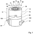
- a protruding from the kitchen plate 30 part of the power supply device forms a connection part 10 for attaching a kitchen appliance 12 and for connecting the kitchen appliance 12 with a household power grid.
- the connecting part 10 has a cylindrical outer surface with a vertically oriented cylinder axis, protrudes by a height of 15 mm beyond the kitchen plate 30 and has a diameter D of 60 mm.
- the fitting 10 On a circular surface, the fitting 10 has two concentric openings 58, 60 in the shape of an annular slot. Further, the connector 10 has a central, circular opening 66 which is concentric with the annular openings 58, 60. The centers of the annular shape of the openings 58, 60 and the opening 66 lie on the cylinder axis of the connecting part 10.
- a width B of the openings 58, 60 is about 1.5 mm and is thus significantly less than one-tenth of the diameter D of the connecting part 10th
- An outer diameter of the outer opening 60 is 40 mm, and an outer diameter of the smaller opening 58 is 25 mm.
- the inner diameter of the annular openings 58, 60 are smaller by 3 mm than the outer diameter.
- a housing of the connection part 10 consists of an upper housing part 76, in which the openings 58, 60, 66 are introduced, from a second housing part 84, which forms an intermediate floor, and a lower shell 104.
- the lower housing part 84 has three evenly over a Circumferentially distributed fastening tabs 106 which engage axially during assembly in corresponding recesses on the upper housing part 84 and each having a hole for a screw, by means of which the housing parts 76, 84 are screwed together radially.
- the lower shell 104 is screwed during assembly with the second housing part 84.
- connection part 10 On the lower shell 104, two opposing, designed as in installation position horizontally outwardly projecting paragraphs fasteners 32, 34 are formed, each having a hole for receiving a screw 108, 108 ', by means of the power supply device screwed to the kitchen plate 30 can be.
- An axial distance H between a contact surface of the fastening means 32, 34 and the circular top of the connection part 10 is 60 mm, so that the connection part 10 in the mounted state in the kitchen plate 30 with a standard thickness of 45 mm by 15 mm above the surface of the kitchen plate 30th protrudes.
- the annular openings 58, 66 are in the in FIG. 1 shown closed configuration without plugged kitchen appliance 12 of accurately fitting, also annular cover members 36, 38 closed.
- the circular opening 66 is closed by a precisely fitting, pin-shaped cover member 40.
- the upper edges of the cover members 36-40 terminate flush with the circular surface of the fitting 10.
- the cover elements 36-40 are part of a cover device 14 of the power supply device and are each independently deflectable against a spring force in the axial direction downwards or in the direction of the kitchen plate 30.
- the openings 58, 60, 66 widen inwards in the axial direction, so that in each case an undercut 56 - 56 '"is formed, which is interrupted only by narrow, axially extending guide ribs 110, 112.
- the inner sides of the guide ribs 110, 112 form Guide surfaces 52, 54 for guiding the cover members 36, 38 in the axial direction, thereby securely blocking the case 76 with the cover members 36 - 40.
- the cover elements 36, 38 are generally cylindrical-jacket-shaped and have at a lower, the openings 58, 60 facing away from a plurality of slot-shaped recesses, each extending axially ( FIG. 4 ).
- a first type of recesses separates three at one end to the corresponding cover member 36, 38 integrally formed locking tongues 70, 70 'of a jacket of the cover 36, 38, so that the locking tongues 70, 70' can deflect relative to the jacket in the radial direction.
- each of the locking tongues 70, 70 'on a locking lug 72 At a free end, each of the locking tongues 70, 70 'on a locking lug 72.
- larger cover member 38 point radially inward, while the latching lugs, not shown here, of the smaller cover 36 have radially outward.
- the latching tongues 70, 70 ' are formed on the cover element 38 in layers which are different by 120 ° in each case.
- Three further recesses 74-74 are also distributed at intervals of 120 ° about the circumference of the cover member 38 and serve to guide the cover member 38 in the axial direction when deflecting from the closed configuration and for fixing a rotational position of the cover member 38 relative to a housing part 76th of the connecting part 10, in which also the openings 58, 60, 66 are arranged
- the housing part 76 has three ribs 78, 78 'which extend in the radial direction and are arranged at intervals of 120 °, which in the assembled state of the power supply device into the recesses 74 - 74 "intervene.
- a width of the ribs 78, 78 ' is equal to the width of the recesses 74-74 "except for a mounting clearance and is about 3 mm.
- Three further recesses 80-80 are likewise distributed at intervals of 120 ° over the circumference of the cover element 38 and serve to hold in each case a spiral spring 82 which is supported on a second housing part 84 in the axial direction prevent, are at the bottom of the recesses 80 - 80 "and arranged on the housing part 84 each centering, which engage from both sides in the coil spring 82.
- the cover element 36 has recesses and latching tongues which are analogous to the recesses 74-74 ", 80-80" and latching tongues 70, 70 'of the illustrated cover element 38.
- the coil springs 82 bias the cover members 36, 38 upward in the axial direction.
- the locking lugs 72, 72 'come to corresponding, on the housing part 76 and the guide ribs 110, 112 integrally formed locking lugs to the system and thus support the spring force of the coil springs 82 on the housing part 76 from.
- the cover elements 36, 38 are inserted axially from above into the openings 58, 60.
- the latching tongues 70-70 "deform radially inward until the latching lugs 72, 72' engage and a latching connection is produced between the cover elements 36, 38 and the housing part 76 ,
- the pin-shaped cover member 40 is also loaded by a coil spring 82 'and can be moved against the spring force of the coil spring 82' down.
- a collar 86 is formed to support the coil spring 82 'and as a stop up to the pin-shaped cover member 40.
- the cover elements 36, 38 each have a in the axial direction through openings in the housing part 84 in a lower portion of the power supply device extending into switching tongue 88, 90, the free end has a circumferentially inclined, inclined by about 45 ° surface 92, 102 ,
- two as micro switch 94, 96 formed switching elements are arranged, each having a housing 118, 120, two contacts and a displaceable in the installed state in the circumferential direction switching knob 98, 100.
- the switching tongues 88, 90 lie with the inclined surfaces 92, 102 on the switch buttons 98, 100, so that the spring-loaded buttons 98, 100 are horizontally displaced in the installed position in the housing 118, 120 of the respective microswitch 94, 96 and there a make conductive connection between the contacts of the micro-switches 94, 96.
- the microswitches 94, 96 together form a switching device 114.
- the housing part 84 also three band-shaped contact elements 18 - 22 are poured, which are supported in the closed configuration in the radial direction with a grinder respectively on the side surfaces of the cover 36 - 40 and with open cover 14 by its spring force into the respective opening 58th , 60, 66 are pushed into it.
- the free ends of the contact elements 18-22 have a distance 48 of 8 mm to the circular surface of the housing part 76 or of the connection part 10.
- FIG. 2 shown in a section kitchen appliance 12 has a plug-in element 16 for entering a plug connection with the connection part 10, the essential components of which are two annular, concentric contact elements 44, 46 with cylinder jacket-shaped inner and outer surfaces and a pin-shaped contact element 42 with a round cross-section.
- the dimensions of the contact elements 42 - 46 correspond to the dimensions of the openings 58, 60, 66, so that the contact elements 42 - 46 for attaching the kitchen appliance 12 to the connector 10 in the openings 58, 60, 66 engage and so that during a Aufsteckterrorism the cover elements 36 - 40 are moved in the axial direction into the interior of the connection part 10.
- the contact elements 18-22 contact the contact elements 42-46 and enclose three conductor plates 24-28 which pass through the kitchen plate 30 and are formed by the contact elements 18-22 and the contact elements 42 46.
- FIG. 3 shows that
- the kitchen appliance 12 has a circular base portion 62, with which it is supported directly on the kitchen plate 30 in a plugged onto the connector part 10 state, so that the kitchen plate 30 and not the connector 10 carries a major part of a weight of the kitchen appliance 12.
- the base region 62 covers the connection part 10.
- the kitchen plate 30 therefore assumes the function of a base for the kitchen appliance 12.
- the base region 62 of the kitchen appliance 12 is fastened directly to a housing 64 of the kitchen appliance 12.
- the contact element 22 is connected via the micro switch 94 to a negative terminal of the household power network
- the contact element 20 is connected via the switched microswitch 96 with a positive pole of the household power network
- the contact element 18 is directly connected to a neutral conductor of the household electricity network ( FIG. 4 ).
- the contact element 18 therefore closes a protective conductor contact 116, namely in a Aufsteckvorgang of the kitchen appliance 12 in advance, ie in front of the contact elements 20, 22, and after pulling off the kitchen appliance 12 lagging.
- the person skilled in the art can switch a potentiometer and / or a switching element 124 between the power supply device and a main part of the household power supply network at will.
- a voltage only reaches the contact element 20 when the cover element 36 covering the contact element 22 is deflected, and the contact element 22 is only connected to the household power grid when the cover element 38 covers the contact element 20 is.
- a circuit comprising the kitchen appliance 12 is closed only when both cover elements 36, 38 are simultaneously and far enough deflected from their closed configuration.
- the mechanical connection through the tabs 88, 90 is in FIG. 4 represented by dashed arrows. Can therefore be connected via the cover 38, the covered by the cover 36 contact element 20, and The cover element 36 covers the contact element 22 covered by the cover element 38.
- the closing of the micro-switch 94, 96 takes place when plugging the kitchen appliance 12 only after a displacement of the cover 36 - 40, which is longer than a displacement, in which the contact elements 18 - 22 of the kitchen appliance 12 and the contact elements 42 - 46 of the connecting part 10th touch.
- a gas discharge between the kitchen appliance 12 and the connection part 10 when plugging or unplugging the kitchen appliance 12 can be avoided.
- the contact elements 42 - 46 are initially separated analogously from the household power grid and only then from the contact elements 18 - 22 of the kitchen appliance 12.
- a tubular drainage means 50 is formed, the liquid dripping into the power supply device on the microswitches 94, 96 passes.
- a hole for passing a connection cable 122 connected to the house power network is arranged. The hole is large enough to allow dripping of the liquid.
- FIG. 5 shows the connection part 10 in an installed state in an oblique view.
- a switching element 124 is arranged, by means of which an operator can activate and deactivate the power supply device. Further, the operator may determine a voltage applied to the contact elements 20, 22.
- FIGS. 7 and 8 show various built-in power supply devices in the Figures 1 - 5 shown type. Analogous features are provided with the same reference numerals. For a description of the connection parts 10, 10 'is to the description of the Figures 1-6 directed.
- FIG. 7 shows a modular cooking hob 126 with a first module comprising a kitchen plate 30 with two integrated connection parts 10, 10 '. Further, the hob 126 includes a glass ceramic hob 128 and a two-flame gas hob 130. A common control panel 132, both the connecting parts 10, 10 'and the glass ceramic hob 128 and the gas hob 130 are actuated.
- FIG. 8 shows a built-in device with two connection parts 10, 10 'and with a controller 134 with two switches 136, 138, which are each associated with one of the connecting parts 10, 10'.
- reference numeral 10 connector 62 plinth 12 kitchen appliance 64 casing 14 covering 66 opening 16 plug-in element 70 catch tongue 18 contact element 72 locking lug 20 contact element 74 recess 22 contact element 76 housing part 24 conductor path 78 rib 26 conductor path 80 recess 28 conductor path 82 spiral spring 30 kitchen plate 84 housing part 32 fastener 86 collar 34 fastener 88 reed 36 cover 90 reed 38 cover 92 area 40 cover 94 microswitch 42 contact element 96 microswitch 44 contact element 98 selector 46 contact element 100 selector 48 distance 102 area 50 drainer 104 subshell 52 guide surface 106 mounting tab 54 guide surface 108 screw 56 undercut 110 guide rib 58 opening 112 guide rib 60 opening 114 switching device 116 A ground contact 132 Control panel 118 casing 134 control unit 120
Landscapes
- Connector Housings Or Holding Contact Members (AREA)
- Direct Current Feeding And Distribution (AREA)
Claims (9)
- Dispositif d'alimentation électrique avec une pièce de raccordement (10) destinée au branchement d'un appareil culinaire (12) avec un élément de contact (18-22) destiné à entrer en contact avec l'appareil culinaire (12) et avec un dispositif de commutation (114) destiné à la connexion de l'élément de contact (18-22) à un réseau électrique, dans lequel le dispositif de commutation (114) comprend au moins deux éléments de commutation (94, 96) actionnables indépendamment l'un par rapport à l'autre, caractérisé en ce qu'au moins l'un des éléments de commutation (94, 96) comprend un boîtier (118, 120) avec un bouton de commutation (98, 100) déplaçable horizontalement dans la position de montage.
- Dispositif d'alimentation électrique selon la revendication 1, caractérisé par au moins un dispositif de recouvrement (14) commandé par ressort qui est prévu pour être déplacé d'une position de recouvrement dans une position ouverte par un élément enfichable (16) correspondant de l'appareil culinaire (12).
- Dispositif d'alimentation électrique selon la revendication 2, caractérisé en ce que le dispositif de recouvrement (14) comprend au moins deux éléments de recouvrement commandés par ressort déplaçables indépendamment l'un par rapport à l'autre (36-40) pour la commutation respectivement d'un élément de commutation (94, 96).
- Dispositif d'alimentation électrique selon la revendication 3, caractérisé en ce qu'au moins un premier élément de recouvrement (38, 40) est prévu pour le câblage d'un élément de contact (20, 22), qui est recouvert par un deuxième élément de recouvrement (40, 38).
- Dispositif d'alimentation électrique selon l'une des revendications 3 et 4, caractérisé en ce que les deux éléments de recouvrement (38, 40) sont prévus pour le câblage de l'élément de contact (20, 22) recouvert par respectivement l'autre élément de recouvrement (38, 40).
- Dispositif d'alimentation électrique selon l'une des revendications précédentes, caractérisé en ce que les éléments de commutation (94, 96) sont reliés à un circuit ET logique.
- Dispositif d'alimentation électrique selon l'une des revendications précédentes, caractérisé en ce qu'au moins un élément de commutation (94, 96) n'est actionnable avec un élément de contact (42, 46) correspondant de l'élément enfichable (16) que lorsque le contact de l'élément de contact (18, 20) est fermé.
- Dispositif d'alimentation électrique selon l'une des revendications précédentes, caractérisé en ce qu'au moins un élément de commutation (94, 96) n'est actionnable que lorsque le contact de conducteur de protection (116) est fermé.
- Dispositif d'alimentation électrique selon l'une des revendications précédentes, caractérisé par un moyen de drainage (50) destiné à l'assèchement du dispositif de commutation (114).
Applications Claiming Priority (1)
| Application Number | Priority Date | Filing Date | Title |
|---|---|---|---|
| DE200410063283 DE102004063283A1 (de) | 2004-12-29 | 2004-12-29 | Stromversorgungsvorrichtung mit einem Anschlussteil |
Publications (3)
| Publication Number | Publication Date |
|---|---|
| EP1676507A2 EP1676507A2 (fr) | 2006-07-05 |
| EP1676507A3 EP1676507A3 (fr) | 2014-05-07 |
| EP1676507B1 true EP1676507B1 (fr) | 2016-07-20 |
Family
ID=36072178
Family Applications (1)
| Application Number | Title | Priority Date | Filing Date |
|---|---|---|---|
| EP05109926.5A Expired - Lifetime EP1676507B1 (fr) | 2004-12-29 | 2005-10-25 | Dispositif d'alimentation électrique comportant une partie de connexion |
Country Status (2)
| Country | Link |
|---|---|
| EP (1) | EP1676507B1 (fr) |
| DE (1) | DE102004063283A1 (fr) |
Families Citing this family (6)
| Publication number | Priority date | Publication date | Assignee | Title |
|---|---|---|---|---|
| GB2440373A (en) * | 2006-07-26 | 2008-01-30 | Otter Controls Ltd | A cordless electrical connector with a seal |
| GB2445787B (en) * | 2007-01-16 | 2010-03-03 | Robin William Shapero | Power or data connector for appliances |
| DE102008009354B4 (de) * | 2008-02-14 | 2011-02-24 | Bowa-Electronic Gmbh & Co. Kg | Steckverbindung für einen chirurgischen Hochfrequenzgenerator |
| WO2011027608A1 (fr) * | 2009-09-01 | 2011-03-10 | オリンパスメディカルシステムズ株式会社 | Connecteur électrique et endoscope |
| DE102010063464A1 (de) * | 2010-12-17 | 2012-06-21 | BSH Bosch und Siemens Hausgeräte GmbH | Anschlusselement, Haushaltsgerät mit solchem Anschlusselement und Einsetzmodul |
| EP3701846B1 (fr) * | 2019-02-27 | 2024-07-31 | Vorwerk & Co. Interholding GmbH | Dispositif de réception permettant de recevoir au moins un récipient de préparation pour aliments doté d'un dispositif chauffant |
Family Cites Families (10)
| Publication number | Priority date | Publication date | Assignee | Title |
|---|---|---|---|---|
| NL285681A (fr) * | 1961-11-20 | 1900-01-01 | ||
| EP0268722A1 (fr) * | 1986-11-21 | 1988-06-01 | ELETTRODOMUS S.p.A. | Fer à repasser muni d'une résistance électrique et du type sans cordon |
| DE3739318A1 (de) | 1987-11-20 | 1989-06-01 | Stephan Vandaele | Elektrokochgeraet |
| DE4103792A1 (de) * | 1991-02-08 | 1992-08-20 | Braun Ag | Haushaltsgeraet |
| US5277602A (en) * | 1992-11-25 | 1994-01-11 | Yi Lee M | Electrical plug and receptacle assembly |
| GB9319159D0 (en) * | 1993-09-16 | 1993-11-03 | Strix Ltd | Cordless electrical appliances and connectors therefor |
| DE19655071C2 (de) * | 1996-06-12 | 2000-12-14 | Bsh Bosch Siemens Hausgeraete | Kochmulde mit Steckkupplungsteil |
| US6310306B1 (en) * | 2000-04-03 | 2001-10-30 | John Norling | Safety wall socket assembly |
| GB2374735B (en) * | 2001-04-20 | 2003-10-08 | Kettle Solutions Ltd | Electrical connector |
| DE20306052U1 (de) * | 2003-04-15 | 2003-06-12 | Wu, Chia-Hsiung, Taipeh/T'ai-pei | Elektrische Fassung eines leitfähigen Untersatzes |
-
2004
- 2004-12-29 DE DE200410063283 patent/DE102004063283A1/de not_active Withdrawn
-
2005
- 2005-10-25 EP EP05109926.5A patent/EP1676507B1/fr not_active Expired - Lifetime
Also Published As
| Publication number | Publication date |
|---|---|
| EP1676507A3 (fr) | 2014-05-07 |
| EP1676507A2 (fr) | 2006-07-05 |
| DE102004063283A1 (de) | 2006-07-13 |
Similar Documents
| Publication | Publication Date | Title |
|---|---|---|
| DE69534828T2 (de) | Gerät zum Erhitzen einer Flüssigkeit | |
| DE69333370T3 (de) | Elektrisches schnurloses Wasserheizgerät | |
| DE20116490U1 (de) | Elektrischer Brattopf | |
| DE202007019573U1 (de) | Schnurloser elektrischer Verbinder | |
| DE102008009142A1 (de) | Elektrische Verbindungseinrichtung | |
| DE3834626C2 (fr) | ||
| EP1676507A2 (fr) | Dispositif d'alimentation électrique comportant une partie de connexion | |
| DE102010021772A1 (de) | Anschlussanordnung zum Schließen eines elektrischen Kontakts | |
| EP1679474B1 (fr) | Dispositif d'alimentation électrique | |
| DE29601440U1 (de) | Steckdose mit einem Modul für Zusatzfunktionen | |
| EP1278443B1 (fr) | Bouilloire a temperature d'eau reglable | |
| EP1272081B1 (fr) | Appareil electromenager | |
| DE19830579C2 (de) | Verlängerungsrohranordnung für Staubsauger | |
| DE60215714T2 (de) | Elektrischer Verbinder | |
| DE3728535A1 (de) | Herdplatte | |
| DE69701652T2 (de) | Klemmbrett mit integriertem Entstörfilter insbesondere für elektrische Haushaltgeräte | |
| DE3439906C2 (fr) | ||
| DE29702211U1 (de) | Grundplatte mit Steckkontakten | |
| DE4013074A1 (de) | Einstellbares geraet, insbesondere elektrisches schalt-, steuer- oder regelgeraet | |
| EP0117286B1 (fr) | Dispositif de couplage | |
| EP0813031A2 (fr) | Plaque de cuisson à connecteur électrique | |
| DE4324092C1 (de) | Elektrische Schalter-Stecker-Kombination | |
| DE19801347C1 (de) | Mehrpolige elektrische Steckverbindung | |
| EP1182734A2 (fr) | Appareil électromécanique de contrôle pour un appareil de chauffage électrique | |
| WO2006092354A1 (fr) | Systeme de connexion/deconnexion et appareil electrique |
Legal Events
| Date | Code | Title | Description |
|---|---|---|---|
| PUAI | Public reference made under article 153(3) epc to a published international application that has entered the european phase |
Free format text: ORIGINAL CODE: 0009012 |
|
| AK | Designated contracting states |
Kind code of ref document: A2 Designated state(s): AT BE BG CH CY CZ DE DK EE ES FI FR GB GR HU IE IS IT LI LT LU LV MC NL PL PT RO SE SI SK TR |
|
| AX | Request for extension of the european patent |
Extension state: AL BA HR MK YU |
|
| PUAL | Search report despatched |
Free format text: ORIGINAL CODE: 0009013 |
|
| AK | Designated contracting states |
Kind code of ref document: A3 Designated state(s): AT BE BG CH CY CZ DE DK EE ES FI FR GB GR HU IE IS IT LI LT LU LV MC NL PL PT RO SE SI SK TR |
|
| AX | Request for extension of the european patent |
Extension state: AL BA HR MK YU |
|
| RIC1 | Information provided on ipc code assigned before grant |
Ipc: A47J 27/62 20060101ALI20140401BHEP Ipc: A47J 27/21 20060101AFI20140401BHEP Ipc: H01R 13/703 20060101ALI20140401BHEP |
|
| 17P | Request for examination filed |
Effective date: 20141107 |
|
| RBV | Designated contracting states (corrected) |
Designated state(s): AT BE BG CH CY CZ DE DK EE ES FI FR GB GR HU IE IS IT LI LT LU LV MC NL PL PT RO SE SI SK TR |
|
| AKX | Designation fees paid |
Designated state(s): AT BE BG CH CY CZ DE DK EE ES FI FR GB GR HU IE IS IT LI LT LU LV MC NL PL PT RO SE SI SK TR |
|
| AXX | Extension fees paid |
Extension state: MK Extension state: BA Extension state: AL Extension state: YU Extension state: HR |
|
| RAP1 | Party data changed (applicant data changed or rights of an application transferred) |
Owner name: BSH HAUSGERAETE GMBH |
|
| GRAP | Despatch of communication of intention to grant a patent |
Free format text: ORIGINAL CODE: EPIDOSNIGR1 |
|
| INTG | Intention to grant announced |
Effective date: 20160216 |
|
| GRAS | Grant fee paid |
Free format text: ORIGINAL CODE: EPIDOSNIGR3 |
|
| GRAA | (expected) grant |
Free format text: ORIGINAL CODE: 0009210 |
|
| AK | Designated contracting states |
Kind code of ref document: B1 Designated state(s): AT BE BG CH CY CZ DE DK EE ES FI FR GB GR HU IE IS IT LI LT LU LV MC NL PL PT RO SE SI SK TR |
|
| REG | Reference to a national code |
Ref country code: GB Ref legal event code: FG4D Free format text: NOT ENGLISH |
|
| REG | Reference to a national code |
Ref country code: CH Ref legal event code: EP |
|
| REG | Reference to a national code |
Ref country code: IE Ref legal event code: FG4D Free format text: LANGUAGE OF EP DOCUMENT: GERMAN |
|
| REG | Reference to a national code |
Ref country code: AT Ref legal event code: REF Ref document number: 813284 Country of ref document: AT Kind code of ref document: T Effective date: 20160815 |
|
| REG | Reference to a national code |
Ref country code: DE Ref legal event code: R096 Ref document number: 502005015286 Country of ref document: DE |
|
| REG | Reference to a national code |
Ref country code: LT Ref legal event code: MG4D |
|
| REG | Reference to a national code |
Ref country code: NL Ref legal event code: MP Effective date: 20160720 |
|
| PG25 | Lapsed in a contracting state [announced via postgrant information from national office to epo] |
Ref country code: FI Free format text: LAPSE BECAUSE OF FAILURE TO SUBMIT A TRANSLATION OF THE DESCRIPTION OR TO PAY THE FEE WITHIN THE PRESCRIBED TIME-LIMIT Effective date: 20160720 Ref country code: IT Free format text: LAPSE BECAUSE OF FAILURE TO SUBMIT A TRANSLATION OF THE DESCRIPTION OR TO PAY THE FEE WITHIN THE PRESCRIBED TIME-LIMIT Effective date: 20160720 Ref country code: NL Free format text: LAPSE BECAUSE OF FAILURE TO SUBMIT A TRANSLATION OF THE DESCRIPTION OR TO PAY THE FEE WITHIN THE PRESCRIBED TIME-LIMIT Effective date: 20160720 Ref country code: IS Free format text: LAPSE BECAUSE OF FAILURE TO SUBMIT A TRANSLATION OF THE DESCRIPTION OR TO PAY THE FEE WITHIN THE PRESCRIBED TIME-LIMIT Effective date: 20161120 Ref country code: LT Free format text: LAPSE BECAUSE OF FAILURE TO SUBMIT A TRANSLATION OF THE DESCRIPTION OR TO PAY THE FEE WITHIN THE PRESCRIBED TIME-LIMIT Effective date: 20160720 |
|
| PGFP | Annual fee paid to national office [announced via postgrant information from national office to epo] |
Ref country code: DE Payment date: 20161031 Year of fee payment: 12 |
|
| PG25 | Lapsed in a contracting state [announced via postgrant information from national office to epo] |
Ref country code: SE Free format text: LAPSE BECAUSE OF FAILURE TO SUBMIT A TRANSLATION OF THE DESCRIPTION OR TO PAY THE FEE WITHIN THE PRESCRIBED TIME-LIMIT Effective date: 20160720 Ref country code: BE Free format text: LAPSE BECAUSE OF NON-PAYMENT OF DUE FEES Effective date: 20161031 Ref country code: LV Free format text: LAPSE BECAUSE OF FAILURE TO SUBMIT A TRANSLATION OF THE DESCRIPTION OR TO PAY THE FEE WITHIN THE PRESCRIBED TIME-LIMIT Effective date: 20160720 Ref country code: PL Free format text: LAPSE BECAUSE OF FAILURE TO SUBMIT A TRANSLATION OF THE DESCRIPTION OR TO PAY THE FEE WITHIN THE PRESCRIBED TIME-LIMIT Effective date: 20160720 Ref country code: ES Free format text: LAPSE BECAUSE OF FAILURE TO SUBMIT A TRANSLATION OF THE DESCRIPTION OR TO PAY THE FEE WITHIN THE PRESCRIBED TIME-LIMIT Effective date: 20160720 Ref country code: GR Free format text: LAPSE BECAUSE OF FAILURE TO SUBMIT A TRANSLATION OF THE DESCRIPTION OR TO PAY THE FEE WITHIN THE PRESCRIBED TIME-LIMIT Effective date: 20161021 Ref country code: PT Free format text: LAPSE BECAUSE OF FAILURE TO SUBMIT A TRANSLATION OF THE DESCRIPTION OR TO PAY THE FEE WITHIN THE PRESCRIBED TIME-LIMIT Effective date: 20161121 |
|
| REG | Reference to a national code |
Ref country code: DE Ref legal event code: R097 Ref document number: 502005015286 Country of ref document: DE |
|
| PG25 | Lapsed in a contracting state [announced via postgrant information from national office to epo] |
Ref country code: EE Free format text: LAPSE BECAUSE OF FAILURE TO SUBMIT A TRANSLATION OF THE DESCRIPTION OR TO PAY THE FEE WITHIN THE PRESCRIBED TIME-LIMIT Effective date: 20160720 Ref country code: RO Free format text: LAPSE BECAUSE OF FAILURE TO SUBMIT A TRANSLATION OF THE DESCRIPTION OR TO PAY THE FEE WITHIN THE PRESCRIBED TIME-LIMIT Effective date: 20160720 |
|
| PLBE | No opposition filed within time limit |
Free format text: ORIGINAL CODE: 0009261 |
|
| STAA | Information on the status of an ep patent application or granted ep patent |
Free format text: STATUS: NO OPPOSITION FILED WITHIN TIME LIMIT |
|
| PG25 | Lapsed in a contracting state [announced via postgrant information from national office to epo] |
Ref country code: BG Free format text: LAPSE BECAUSE OF FAILURE TO SUBMIT A TRANSLATION OF THE DESCRIPTION OR TO PAY THE FEE WITHIN THE PRESCRIBED TIME-LIMIT Effective date: 20161020 Ref country code: CZ Free format text: LAPSE BECAUSE OF FAILURE TO SUBMIT A TRANSLATION OF THE DESCRIPTION OR TO PAY THE FEE WITHIN THE PRESCRIBED TIME-LIMIT Effective date: 20160720 Ref country code: DK Free format text: LAPSE BECAUSE OF FAILURE TO SUBMIT A TRANSLATION OF THE DESCRIPTION OR TO PAY THE FEE WITHIN THE PRESCRIBED TIME-LIMIT Effective date: 20160720 Ref country code: SK Free format text: LAPSE BECAUSE OF FAILURE TO SUBMIT A TRANSLATION OF THE DESCRIPTION OR TO PAY THE FEE WITHIN THE PRESCRIBED TIME-LIMIT Effective date: 20160720 |
|
| REG | Reference to a national code |
Ref country code: CH Ref legal event code: PL |
|
| 26N | No opposition filed |
Effective date: 20170421 |
|
| GBPC | Gb: european patent ceased through non-payment of renewal fee |
Effective date: 20161025 |
|
| REG | Reference to a national code |
Ref country code: IE Ref legal event code: MM4A |
|
| REG | Reference to a national code |
Ref country code: FR Ref legal event code: ST Effective date: 20170630 |
|
| PG25 | Lapsed in a contracting state [announced via postgrant information from national office to epo] |
Ref country code: GB Free format text: LAPSE BECAUSE OF NON-PAYMENT OF DUE FEES Effective date: 20161025 Ref country code: FR Free format text: LAPSE BECAUSE OF NON-PAYMENT OF DUE FEES Effective date: 20161102 Ref country code: CH Free format text: LAPSE BECAUSE OF NON-PAYMENT OF DUE FEES Effective date: 20161031 Ref country code: LI Free format text: LAPSE BECAUSE OF NON-PAYMENT OF DUE FEES Effective date: 20161031 |
|
| PG25 | Lapsed in a contracting state [announced via postgrant information from national office to epo] |
Ref country code: SI Free format text: LAPSE BECAUSE OF FAILURE TO SUBMIT A TRANSLATION OF THE DESCRIPTION OR TO PAY THE FEE WITHIN THE PRESCRIBED TIME-LIMIT Effective date: 20160720 Ref country code: LU Free format text: LAPSE BECAUSE OF NON-PAYMENT OF DUE FEES Effective date: 20161025 |
|
| PG25 | Lapsed in a contracting state [announced via postgrant information from national office to epo] |
Ref country code: IE Free format text: LAPSE BECAUSE OF NON-PAYMENT OF DUE FEES Effective date: 20161025 |
|
| REG | Reference to a national code |
Ref country code: BE Ref legal event code: MM Effective date: 20161031 |
|
| REG | Reference to a national code |
Ref country code: AT Ref legal event code: MM01 Ref document number: 813284 Country of ref document: AT Kind code of ref document: T Effective date: 20161025 |
|
| PG25 | Lapsed in a contracting state [announced via postgrant information from national office to epo] |
Ref country code: AT Free format text: LAPSE BECAUSE OF NON-PAYMENT OF DUE FEES Effective date: 20161025 |
|
| REG | Reference to a national code |
Ref country code: DE Ref legal event code: R119 Ref document number: 502005015286 Country of ref document: DE |
|
| PG25 | Lapsed in a contracting state [announced via postgrant information from national office to epo] |
Ref country code: HU Free format text: LAPSE BECAUSE OF FAILURE TO SUBMIT A TRANSLATION OF THE DESCRIPTION OR TO PAY THE FEE WITHIN THE PRESCRIBED TIME-LIMIT; INVALID AB INITIO Effective date: 20051025 Ref country code: CY Free format text: LAPSE BECAUSE OF FAILURE TO SUBMIT A TRANSLATION OF THE DESCRIPTION OR TO PAY THE FEE WITHIN THE PRESCRIBED TIME-LIMIT Effective date: 20160720 |
|
| PG25 | Lapsed in a contracting state [announced via postgrant information from national office to epo] |
Ref country code: MC Free format text: LAPSE BECAUSE OF FAILURE TO SUBMIT A TRANSLATION OF THE DESCRIPTION OR TO PAY THE FEE WITHIN THE PRESCRIBED TIME-LIMIT Effective date: 20160720 Ref country code: TR Free format text: LAPSE BECAUSE OF FAILURE TO SUBMIT A TRANSLATION OF THE DESCRIPTION OR TO PAY THE FEE WITHIN THE PRESCRIBED TIME-LIMIT Effective date: 20160720 |
|
| PG25 | Lapsed in a contracting state [announced via postgrant information from national office to epo] |
Ref country code: DE Free format text: LAPSE BECAUSE OF NON-PAYMENT OF DUE FEES Effective date: 20180501 |