EP1676533B1 - Verfahren zur Herstellung einer Nadelvorrichtung zur Verwendung mit einem Biopsiegerät - Google Patents
Verfahren zur Herstellung einer Nadelvorrichtung zur Verwendung mit einem Biopsiegerät Download PDFInfo
- Publication number
- EP1676533B1 EP1676533B1 EP05258094A EP05258094A EP1676533B1 EP 1676533 B1 EP1676533 B1 EP 1676533B1 EP 05258094 A EP05258094 A EP 05258094A EP 05258094 A EP05258094 A EP 05258094A EP 1676533 B1 EP1676533 B1 EP 1676533B1
- Authority
- EP
- European Patent Office
- Prior art keywords
- tissue
- cutter
- elongated tube
- lumen
- piercing tip
- Prior art date
- Legal status (The legal status is an assumption and is not a legal conclusion. Google has not performed a legal analysis and makes no representation as to the accuracy of the status listed.)
- Expired - Lifetime
Links
Images


Classifications
-
- A—HUMAN NECESSITIES
- A61—MEDICAL OR VETERINARY SCIENCE; HYGIENE
- A61B—DIAGNOSIS; SURGERY; IDENTIFICATION
- A61B10/00—Instruments for taking body samples for diagnostic purposes; Other methods or instruments for diagnosis, e.g. for vaccination diagnosis, sex determination or ovulation-period determination; Throat striking implements
- A61B10/02—Instruments for taking cell samples or for biopsy
- A61B10/0233—Pointed or sharp biopsy instruments
- A61B10/0266—Pointed or sharp biopsy instruments means for severing sample
- A61B10/0275—Pointed or sharp biopsy instruments means for severing sample with sample notch, e.g. on the side of inner stylet
-
- A—HUMAN NECESSITIES
- A61—MEDICAL OR VETERINARY SCIENCE; HYGIENE
- A61B—DIAGNOSIS; SURGERY; IDENTIFICATION
- A61B10/00—Instruments for taking body samples for diagnostic purposes; Other methods or instruments for diagnosis, e.g. for vaccination diagnosis, sex determination or ovulation-period determination; Throat striking implements
- A61B10/02—Instruments for taking cell samples or for biopsy
- A61B10/0233—Pointed or sharp biopsy instruments
- A61B10/0283—Pointed or sharp biopsy instruments with vacuum aspiration, e.g. caused by retractable plunger or by connected syringe
-
- Y—GENERAL TAGGING OF NEW TECHNOLOGICAL DEVELOPMENTS; GENERAL TAGGING OF CROSS-SECTIONAL TECHNOLOGIES SPANNING OVER SEVERAL SECTIONS OF THE IPC; TECHNICAL SUBJECTS COVERED BY FORMER USPC CROSS-REFERENCE ART COLLECTIONS [XRACs] AND DIGESTS
- Y10—TECHNICAL SUBJECTS COVERED BY FORMER USPC
- Y10T—TECHNICAL SUBJECTS COVERED BY FORMER US CLASSIFICATION
- Y10T156/00—Adhesive bonding and miscellaneous chemical manufacture
- Y10T156/10—Methods of surface bonding and/or assembly therefor
- Y10T156/1052—Methods of surface bonding and/or assembly therefor with cutting, punching, tearing or severing
- Y10T156/1056—Perforating lamina
-
- Y—GENERAL TAGGING OF NEW TECHNOLOGICAL DEVELOPMENTS; GENERAL TAGGING OF CROSS-SECTIONAL TECHNOLOGIES SPANNING OVER SEVERAL SECTIONS OF THE IPC; TECHNICAL SUBJECTS COVERED BY FORMER USPC CROSS-REFERENCE ART COLLECTIONS [XRACs] AND DIGESTS
- Y10—TECHNICAL SUBJECTS COVERED BY FORMER USPC
- Y10T—TECHNICAL SUBJECTS COVERED BY FORMER US CLASSIFICATION
- Y10T29/00—Metal working
- Y10T29/49—Method of mechanical manufacture
- Y10T29/49826—Assembling or joining
- Y10T29/49885—Assembling or joining with coating before or during assembling
Definitions
- the present invention is related generally to an improved process of manufacturing a needle assembly for use with a biopsy device for acquiring a tissue sample.
- Noninvasive methods for examining tissue include palpation, thermography, PET, SPECT, Nuclear imaging, X-ray, MRI, CT, and ultrasound imaging.
- a biopsy may be done either in an open procedure or in a percutaneous procedure.
- a scalpel is used by the surgeon to create a large incision in the tissue in order to provide direct viewing and access to the tissue mass of interest. Removal of the entire mass (excisional biopsy) or a part of the mass (incisional biopsy) is performed.
- a needle-like instrument is inserted through a very small incision to access the tissue mass of interest and to obtain a tissue sample for later examination and analysis.
- the advantages of the percutaneous method as compared to the open method are significant: less recovery time for the patient, less pain, less surgical time, lower cost, less risk of injury to adjacent bodily tissues such as nerves, and less disfigurement of the patient's anatomy.
- Aspiration and core sampling there are two ways to percutaneously obtain a portion of tissue from within the body: aspiration and core sampling. Aspiration of the tissue through a fine needle requires the tissue to be fragmented into pieces small enough to be withdrawn in a fluid medium. This method is less intrusive than other known sampling techniques, but one may only examine cells in the liquid (cytology) and not the cells and the structure (pathology). In core sampling, a core or fragment of tissue is obtained for histologic examination and/or genetic tests, which may be done via a frozen or paraffin section. The type of biopsy used depends mainly on various factors present in the patient, and no single procedure is ideal for all cases. However, core biopsies seem to be more widely used by physicians.
- a double lumen biopsy needle incorporating vacuum suction to obtain a tissue sample [such as that disclosed in WO 02/062231 ].
- the needle is inserted into a small incision in a patient and is advanced through tissue until the needle is adjacent the tissue of interest.
- a vacuum source may be activated, providing suction inside one of the two lumens.
- the suction is communicated to the second lumen via a passage between the two lumens.
- the second lumen may contain an aperture through which suspicious tissue may be drawn when the vacuum source is activated. Once tissue is drawn into the aperture, the surgeon may advance a cutter through the second lumen in order to excise a sample from the tissue of interest.
- biopsy needles of the type described above are useful in obtaining tissue samples
- the processes known in the art for manufacturing these needles are often expensive and labor-intensive due to the number of components and steps involved.
- certain biopsy needles provide a double lumen structure formed of two separate rigid structures, thus requiring a reliable method of attaching the two structures, such as a weld or adhesive, along the entire length of the lumens.
- many biopsy needles include a sharpened feature on the leading end of the needle that cuts through tissue as the needle is advanced into the body. These sharpened tips often have small components and/or features that require significant time and expense to make and attach to the needle.
- biopsy needles often include a mounting component that allows the needle to be attached to a handle or other platform.
- these mounting components are manufactured separately from the body of the needle, and must be joined together after formation, such as by gluing, a process that is heavily reliant on the skill and concentration of a human worker. Even if a more reliable method of attaching the mounting component to the needle is used, such as induction heating or heat staking, such methods still involve the added expense necessitated by the extra assembly equipment as well as the steps of manufacturing the mounting component and attaching it to the needle.
- the process of the current invention overcomes the above-noted and other deficiencies of the prior art by providing a process for manufacturing a biopsy needle device that reduces the number of components that must be separately manufactured and assembled, thereby reducing the cost of manufacturing the biopsy needle device while maintaining the necessary biomechanical properties.
- a process of manufacturing a biopsy needle may comprise the steps of forming an aperture for receiving tissue to be sampled in an exterior surface of an elongated tube that has a proximal and distal portion, wherein the elongated tube may be configured to receive a cutter; forming a hole in the exterior surface of the elongated tube; and applying a coating of material over the elongated tube to form a lumen for receiving vacuum on the exterior surface of the elongated tube, wherein the hole in the exterior surface of the elongated tube may be adapted to provide communication between an interior of the elongated tube and an interior of the lumen.
- This process advantageously allows the vacuum lumen to be formed over the elongated tube without requiring separate manufacturing and assembly steps, thus reducing assembly costs.
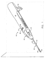
- FIGURE 1 is an isometric view of a hand-held vacuum-assisted biopsy device including a needle assembly manufactured according to one version of the process.
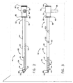
- FIGURE 2 is a side view of a needle assembly manufactured according to one version of the process.
- FIGURE 3 is a top view of a needle assembly manufactured according to one version of the process.
- FIGURE 4 is a side view of a distal tissue-piercing tip manufactured according to one version of the process.
- FIGURE 5 is an isometric view of a distal tissue-piercing tip manufactured according to one version of the process.
- FIGURE 6 is a section view of a cutter lumen and cutter stop manufactured according to one version of the process.
- FIGURE 7 is a section view of a cutter stop manufactured according to one version of the process.
- FIGURE 8 is a partial view of a cutter lumen and axial slide according to one version of the process.
- FIGURE 9 is an isometric view of a needle assembly with slides in place for use in injection molding according to one version of the process.
- FIGURE 10 is a partial frontal cross-sectional view of a needle assembly manufactured according to one version of the process.
- FIGURE 11 is a partial sagittal cross-sectional view of a needle assembly manufactured according to one version of the process.
- FIG. 1 shows a hand-held vacuum-assisted biopsy device 10 comprising a handle 20 detachably connected to a needle assembly 30 having a proximal portion 32 and a distal portion 34 manufactured according to a version of the process of the current invention. Together, they constitute a lightweight, ergonomically-shaped, hand manipulated biopsy device 10.
- needle assembly 30 may be part of a disposable probe that may mount on handle 20.
- hand-held biopsy device 10 may be used in conjunction with an ultrasound to guide needle assembly 30. Since handle 20 may be manipulated by the operator's hand, the operator may steer needle assembly 30 with great freedom towards the tissue mass of interest.
- handle 20 may be held approximately parallel to the chest wall of a patient for obtaining tissue portions closer to the chest wall than may be obtained when needle assembly 30 is attached to another type of device.
- needle assembly 30 may be attached to an electromechanical arm, a platform, a table or other suitable support. Such alternative mountings may be used in conjunction with applications in which the needle assembly is guided by stereotactic (x-ray) or MRI modalities.
- handle 20 may include a forward button 36 which may be used to move a cutter distally through a cutter lumen 40 to sever a sample of suspicious tissue collected in a tissue-receiving port 42. Handle 20 may further include a reverse button 44 which may be used to move cutter proximally through cutter lumen 40, thereby moving the tissue sample in port 42 to a tissue collection surface.
- a vacuum button 48 on handle 20 may be used to open or close a first vacuum line 50 for communicating suction to a vacuum lumen 52 so as to cause tissue to become disposed within port 42 and a second vacuum line 54 for communicating axial suction to cutter to aid in withdrawal of a severed tissue sample.
- Cutter lumen 40 may comprise a proximal portion 56 and a distal portion 58.
- Cutter lumen 40 forms a smooth, uninterrupted passage for receiving cutter such that it may be advanced through the proximal portion 56 of cutter lumen 40 to the distal portion 58.
- Tissue-receiving port 42 may be formed in an exterior surface 60 of cutter lumen 40. Port 42 may be located on the distal portion 58 of cutter lumen 40.
- Cutter lumen 40 may also comprise an open proximal end 62 and an open distal end 64.
- Vacuum lumen 52 may comprise a proximal portion 66 and a distal portion 68.
- cutter lumen 40 may be oriented above vacuum lumen 52.
- a vacuum source (not pictured) may be attached to vacuum lumen 52, possibly at proximal portion 66 thereof, via first vacuum line 50.
- the needle assembly 30 may also include one or more passages, also called interlumen vacuum holes 70, between cutter lumen 40 and vacuum lumen 52.
- interlumen vacuum holes 70 allow that suction to be communicated into cutter lumen 40.
- the interlumen vacuum holes 70 may be located between cutter lumen 40 and vacuum lumen 52 opposite the tissue-receiving port 42.
- a cutter stop 72 may also be located in cutter lumen 40 distally of tissue-receiving port 42.
- a face 74 of cutter stop 72 may provide a cutting surface for severing a tissue sample.
- Face 74 of cutter stop 72 may be designed to match the leading profile of cutter ( FIGS. 6 and 7 ). Depending on the means used to advance cutter, cutter stop 72 may also provide tactile feedback to a surgeon once cutter comes into contact with cutter stop 72 after a sample has been severed. However, if, as known in the art, a computer software program is used to control advancement of cutter, the surgeon will not be provided with tactile feedback by contact between cutter and cutter stop 72.
- a hub 76 having a proximal portion 78 and a distal portion 80 may be located on proximal portion 32 of needle assembly 30.
- Hub 76 assists in mounting needle assembly 30 to handle 20 or other any other suitable support.
- Hub 76 may detachably mount on handle 20 in order to allow disposable needle assembly 30 to be removed from the multiple-use handle 20 after surgery.
- Hub 76 may also include a flange 82 (not pictured) on its proximal portion 301. Flange 82 may snap into a rib or similar retaining element of handle 20 or another suitable support.
- Hub 76 may also include a vacuum manifold 84 that provides a connection between the vacuum source and vacuum lumen 52. Hub 76 may also allow second vacuum line 54 to connect with cutter so that axial suction may be communicated to cutter.
- a distal tissue-piercing tip 86 having a proximal portion 88 and a distal portion 90 may be disposed on distal portion 34 of needle assembly 30.
- distal portion 90 of distal tissue-piercing tip 86 may include a cutting edge 92 of sufficient sharpness to cut through human tissue and thereby aid in moving needle assembly 30 adjacent the tissue of interest.
- the junction of piercing tip 86 and cutter lumen 40 may include a tapered profile therebetween that further assists needle assembly 30 in moving smoothly through a patient's tissue.
- Piercing tip 86 may comprise a substantially flat blade formed of any suitable material.
- Piercing tip 86 may also include tabs 96, 98 on proximal portion 88 thereof to aid in the attachment of piercing tip 86 to cutter lumen 40.
- Tab 96 may be located above tab 98.
- tab 98 extends further toward proximal end 62 of cutter lumen 40 than does tab 96 for reasons addressed below.
- Piercing tip 86 may also include an opening 100, to aid in formation of tapered profile, which is also discussed in more detail below.
- needle assembly 30 may be inserted into a small incision in the body.
- tissue-piercing tip 86 helps needle assembly 30 penetrate through tissue until distal portion 34 of needle assembly 30 is located adjacent the tissue of interest.
- Piercing tip 86 along with tapered profile, may help to minimize tissue drag experienced during insertion and extraction of needle assembly 30.
- Suction may be communicated from vacuum lumen 52 to cutter lumen 40 via the interlumen vacuum holes 70.
- the suction inside cutter lumen 40 actively pulls suspicious tissue into tissue-receiving port 42.
- the surgeon may advance cutter in the distal direction until a sample is severed from the suspicious tissue.
- Cutter stop 72 may be located in cutter lumen 40 distally of tissue-receiving port 42 to provide a cutting surface to aid cutter in severing a sample of suspicious tissue. Once the sample has been severed, cutter may contact cutter stop 72.
- cutter and cutter stop 72 may provide tactile feedback to the surgeon, indicating that a sample has been obtained and that cutter may be withdrawn toward proximal end 62 of cutter lumen 40.
- needle assembly 30 may be repositioned in the patient's body (e.g., rotated, longitudinally translated) in order to obtain another sample.
- cutter may be attached to second vacuum line 54, thereby providing cutter with axial suction.
- axial suction if utilized, may assist cutter in pulling the sample through cutter lumen 40 as cutter is withdrawn.
- the sample may be cleared from cutter onto a tissue collection site located on handle 20 or platform.
- another sample may be obtained by applying vacuum to draw a sample into port 42 and advancing cutter to sever the sample. This procedure may be repeated until the desired number of samples has been acquired.
- cutter lumen 40 may comprise a preformed tube open at each end and cut to the desired length of needle assembly 30.
- the preformed tube may be advantageously straight and round for receiving cutter.
- the material of the preformed tube may be rigid to allow insertion of needle assembly 30 through tissue with minimal deflection.
- cutter lumen 40 may be made of metal. More particularly, cutter lumen 40 may be made of stainless steel.
- Cutter lumen 40 may also be made from other suitable materials, including but not limited to titanium, titanium alloy, aluminum, or aluminum alloy.
- cutter lumen 40 may be made from nonmetallic materials having structural characteristics sufficient to allow a coating of material to be applied over cutter lumen 40 and having the strength and rigidity characteristics sufficient to withstand the force experienced by cutter lumen 40 when it is pressed through human tissue.
- Tissue-receiving port 42 and interlumen vacuum holes 70 may be cut into the preformed tube comprising cutter lumen 40.
- the distal and proximal edges of port 42 may be cut on an angle relative to the longitudinal edges of port 42. The angling of these edges can produce a scissoring effect as needle assembly 30 is pushed through tissue, aiding in positioning the device 10.
- a pair of notches (not pictured) may be cut into distal end 64 of the preformed tube comprising cutter lumen 40 to provide points of attachment for piercing tip 86.
- Piercing tip 86 may be formed of a material providing sufficient strength and rigidity to allow it to move through tissue with minimal deflection.
- tip 86 including the above-described features included thereon, may be stamped from metal sheet stock. More particularly, the metal may be 440A stainless steel. However, other suitable materials may be used, including but not limited to titanium, titanium alloy, aluminum, or aluminum alloy. Non-metallic materials, such as MRI compatible resins, including but not limited to Ultem and Vectra, may be used to form tip 86. Likewise, tip 86 may also be formed from ceramics or glass.
- cutting edge 92 may be sharpened prior to attachment of tip 86 to cutter lumen 40. Cutting edge 92 may be sharpened after formation of tip 86 by grinding perpendicular to cutting edge 92, which is sometimes thought to be advantageous in producing a sharp cutting surface. Alternatively, cutting edge 92 may be sharpened by any other suitable method known in the art.
- Piercing tip 86 may be attached to cutter lumen 40.
- piercing tip 86 may be welded to cutter lumen 40. More particularly, piercing tip 86 may be laser welded to cutter lumen 40. In one version, piercing tip 86 may be welded to cutter lumen 40 at two preformed locations. Tabs 96, 98 of piercing tip 86 may each be welded inside a notch of cutter lumen 40. Alternatively, piercing tip 86 may be attached to cutter lumen 40 through any suitable method known in the art that provides satisfactory strength of attachment between tip 86 and cutter lumen 40, including but not limited to adhesive, press-fit, or screws.
- needle assembly 30 may be formed by applying a coating of material over cutter lumen 40.
- the coating of material may be applied to cutter lumen 40 as a liquid, and then hardened to the necessary rigidity for use in the human body after formation of the desired features thereon.
- the coating of material may be applied to cutter lumen 40 by injection molding.
- the mold (not pictured) is designed such that the injected material may flow into predetermined cavities and form the desired features over cutter lumen 40, including but not limited to vacuum lumen 52 and hub 76.
- the gates (not pictured) through which the material is injected into the mold may be located along the mold part line, shown in FIG. 9 . Further, the gates may be located in the mold underneath cutter lumen 40.
- piercing tip 86 when the material is injected into the mold, it may form an outer sheath 106 over cutter lumen 40, as well as tapered profile between piercing tip 86 and cutter lumen 40.
- piercing tip 86 may include opening 100 ( FIG. 4 ) through which the injected material may flow. Flow of injected material through opening 100 from each side of tip 86 may strengthen attachment of the injected material to piercing tip 86.
- the mold may also be shaped so that the applied material forms hub 76, flange 82, and vacuum manifold 84 over proximal portion 56 of cutter lumen 40.
- the mold may also be designed so that hub 76 extends past proximal end 62 of cutter lumen 40 in order to facilitate the mounting of needle assembly 30 to handle 20 or another suitable support.
- hub 76, including flange 82 and vacuum manifold 84 may be formed separately from the remainder of needle assembly 30 and be attached by gluing, press-fitting or any other suitable method known in the art.
- a slide 108 may be placed along exterior surface 60 of cutter lumen 40, substantially parallel to the longitudinal axis thereof. More particularly, slide 108 may be placed on the underside of exterior surface 60. The material then coats cutter lumen 40 and slide 108, forming vacuum lumen 52 substantially parallel to the longitudinal axis of cutter lumen 40. Slide 108 also serves to prevent the applied material from blocking interlumen vacuum holes 70.
- the mold may also be designed so that slide 108 may be placed in alternate locations in order to orient vacuum lumen 52 above or to either side of cutter lumen 40, so long as at least one interlumen vacuum hole 70 is present between vacuum lumen 52 and cutter lumen 40 to allow suction to be communicated therebetween.
- vacuum lumen 52 in the coating of material applied over cutter lumen 40
- other methods of forming vacuum lumen 52 in the coating of material are also possible.
- vacuum lumen 52 could be drilled out of the coating of material after the material reaches sufficient hardness.
- the coating of material provides the combined cutter lumen 40 and vacuum lumen 52 with an egg-shaped frontal cross-section 110.
- cross-section 110 promotes efficient motion of the needle assembly 30 through tissue.
- the application of a coating of material to cutter lumen 40 may provide needle assembly 30 with cross-sections of various shapes that are consistent with the process of the current invention.
- slide 108 may comprise a scoop-shaped cross-section that provides vacuum lumen 52 with a generally scoop-shaped frontal cross-section 112.
- vacuum lumen 52 and slide 108 could comprise various frontal cross-sections that are consistent with the process of the current invention.
- slide 108 could have a circular frontal cross-section, thus providing vacuum lumen 52 with a circular frontal cross-section.
- tab 98 on piercing tip 86 may be elongated and slope downward in the proximal direction. In addition to serving as a point of attachment for welding piercing tip 86 to cutter lumen 40, tab 98 may also align and help hold slide 108 in place during molding.
- a slide 112 Prior to application of the material to cutter lumen, a slide 112 ( FIG. 9 ) may be inserted into tissue-receiving port 42. Slide 112 prevents any of the applied material from entering port 42.
- an axial slide 114 having a proximal end 116 and a distal end 118 may be inserted into open proximal end 62 of cutter lumen 40 prior to application of the coating of material.
- Axial slide 114 prevents the applied material from entering proximal end 62 of cutter lumen 40.
- axial slide 114 may be of a predetermined length such that distal end 118 extends into cutter lumen 40 distally of tissue-receiving port 42 but does not reach open distal end 62 of cutter lumen 40.
- Distal end 118 of slide 114 may further comprise an indentation 120.
- Piercing tip 86 may be attached to distal end 64 of cutter lumen 40 in a manner that does not prevent material from flowing into open distal end 64 during application of the material over cutter lumen 40. Accordingly, during the application process, material flows into open distal end 64 of cutter lumen 40 and into indentation 120 in axial slide 114, thereby forming cutter stop 72 in cutter lumen 40 distally of tissue-receiving port 42.
- one or more slides may be placed against exterior surface 60 of cutter lumen 40 in order to hold cutter lumen 40 in position while the material is applied over cutter lumen 40 and prevent deformation due to the pressure of the applied material against exterior surface 60.
- outer sheath 106 may include windows 122 ( FIG. 3 ) through which cutter lumen 40 is exposed.
- the injected material may be selected from materials including, but not limited to, plastics, thermoplastics, thermoresins, and polymers.
- the molded features may be formed of a liquid crystal polymer or a glass reinforced polymer.
- One suitable material is a glass reinforced liquid crystal polymer such as VECTRA A130 available from Ticona Corp.
- the injected material may have a melt flow index of at least about 10 grams/minute, more particularly at least about 15 grams/minute. Without being limited by theory, such a mold flow index is thought to be beneficial for molding relatively long, thin-walled cross-sections.
Landscapes
- Health & Medical Sciences (AREA)
- Life Sciences & Earth Sciences (AREA)
- Medical Informatics (AREA)
- Engineering & Computer Science (AREA)
- Biomedical Technology (AREA)
- Heart & Thoracic Surgery (AREA)
- Pathology (AREA)
- Molecular Biology (AREA)
- Surgery (AREA)
- Animal Behavior & Ethology (AREA)
- General Health & Medical Sciences (AREA)
- Public Health (AREA)
- Veterinary Medicine (AREA)
- Surgical Instruments (AREA)
Claims (10)
- Verfahren zur Herstellung einer Biopsienadelvorrichtung, umfassend:Formen einer Öffnung (42) zur Aufnahme von zu entnehmendem Gewebe in einer Außenfläche (60) einer länglichen Röhre (40), die zur Aufnahme einer Schneideinrichtung dient und einen proximalen Abschnitt (56) und einen distalen Abschnitt (58) aufweist,Formen eines Loches (70) in besagter Außenfläche in besagter länglicher Röhre; undAufbringen einer Beschichtung aus Material auf besagte längliche Röhre, um ein Lumen (52) zur Aufnahme eines Vakuums an besagter Außenfläche an besagter länglicher Röhre zu formen, wobei besagtes Loch in besagter Außenfläche der länglichen Röhre eine Verbindung zwischen dem Inneren der besagten länglichen Röhre und dem Inneren des Lumens liefert.
- Verfahren nach Anspruch 1, dadurch gekennzeichnet, daß es Anbringen einer gewebedurchdringenden Spitze (86) an besagtem distalen Abschnitt der länglichen Röhre umfaßt.
- Verfahren nach Anspruch 2, ferner umfassend Stanzen der gewebedurchdringenden Spitze aus Blech vor Anbringen der gewebedurchdringenden Spitze an besagter länglicher Röhre.
- Verfahren nach Anspruch 2, ferner umfassend Stanzen der gewebedurchdringenden Spitze aus Edelstahl vor Anbringen der gewebedurchdringenden Spitze an besagter länglicher Röhre.
- Verfahren nach Anspruch 2, ferner umfassend Schleifen einer Schneidklinge (92) an besagter gewebedurchdringender Spitze vor Anbringen der gewebedurchdringenden Spitze an besagter länglicher Röhre.
- Verfahren nach Anspruch 3, dadurch gekennzeichnet, daß besagte gewebedurchdringende Spitze durch Schweißen an besagter länglicher Röhre angebracht wird.
- Verfahren nach Anspruch 3, dadurch gekennzeichnet, daß besagte gewebedurchdringende Spitze durch Laserschweißen an besagter länglicher Röhre angebracht wird.
- Verfahren nach Anspruch 6, dadurch gekennzeichnet, daß besagte gewebedurchdringende Spitze eine Mehrzahl an Anbringungspunkten aufweist, um besagte gewebedurchdringende Spitze an besagte längliche Röhre zu schweißen.
- Verfahren nach Anspruch 2, dadurch gekennzeichnet, daß besagte gewebedurchdringende Spitze eine Öffnung (100) umfaßt, durch welche besagte Beschichtung von Material fließen kann.
- Verfahren nach Anspruch 1, ferner umfassend Plazieren der länglichen Röhre in einer Form, wobei besagte Beschichtung aus Material auf besagte längliche Röhre durch Spritzgießen aufgebracht wird.
Priority Applications (1)
| Application Number | Priority Date | Filing Date | Title |
|---|---|---|---|
| EP07075501A EP1829485A3 (de) | 2004-12-30 | 2005-12-29 | Verfahren zur Herstellung einer Nadelanordnung zur Verwendung mit einer Biopsievorrichtung |
Applications Claiming Priority (1)
| Application Number | Priority Date | Filing Date | Title |
|---|---|---|---|
| US11/027,120 US20060144548A1 (en) | 2004-12-30 | 2004-12-30 | Method of manufacturing a needle assembly for use with a biopsy device |
Related Child Applications (1)
| Application Number | Title | Priority Date | Filing Date |
|---|---|---|---|
| EP07075501A Division EP1829485A3 (de) | 2004-12-30 | 2005-12-29 | Verfahren zur Herstellung einer Nadelanordnung zur Verwendung mit einer Biopsievorrichtung |
Publications (2)
| Publication Number | Publication Date |
|---|---|
| EP1676533A1 EP1676533A1 (de) | 2006-07-05 |
| EP1676533B1 true EP1676533B1 (de) | 2008-08-27 |
Family
ID=36046804
Family Applications (2)
| Application Number | Title | Priority Date | Filing Date |
|---|---|---|---|
| EP05258094A Expired - Lifetime EP1676533B1 (de) | 2004-12-30 | 2005-12-29 | Verfahren zur Herstellung einer Nadelvorrichtung zur Verwendung mit einem Biopsiegerät |
| EP07075501A Withdrawn EP1829485A3 (de) | 2004-12-30 | 2005-12-29 | Verfahren zur Herstellung einer Nadelanordnung zur Verwendung mit einer Biopsievorrichtung |
Family Applications After (1)
| Application Number | Title | Priority Date | Filing Date |
|---|---|---|---|
| EP07075501A Withdrawn EP1829485A3 (de) | 2004-12-30 | 2005-12-29 | Verfahren zur Herstellung einer Nadelanordnung zur Verwendung mit einer Biopsievorrichtung |
Country Status (8)
| Country | Link |
|---|---|
| US (4) | US20060144548A1 (de) |
| EP (2) | EP1676533B1 (de) |
| JP (1) | JP4781815B2 (de) |
| CN (1) | CN100579466C (de) |
| AU (1) | AU2005245226A1 (de) |
| CA (1) | CA2531154A1 (de) |
| DE (1) | DE602005009312D1 (de) |
| ES (1) | ES2311941T3 (de) |
Families Citing this family (56)
| Publication number | Priority date | Publication date | Assignee | Title |
|---|---|---|---|---|
| US9314228B2 (en) | 2002-05-31 | 2016-04-19 | Vidacare LLC | Apparatus and method for accessing the bone marrow |
| WO2008033871A2 (en) | 2006-09-12 | 2008-03-20 | Vidacare Corporation | Apparatus and methods for biopsy and aspiration of bone marrow |
| US8668698B2 (en) | 2002-05-31 | 2014-03-11 | Vidacare Corporation | Assembly for coupling powered driver with intraosseous device |
| IL165224A0 (en) | 2002-05-31 | 2005-12-18 | Vidacare Corp | Apparatus and method to access bone marrow |
| US10973532B2 (en) | 2002-05-31 | 2021-04-13 | Teleflex Life Sciences Limited | Powered drivers, intraosseous devices and methods to access bone marrow |
| US9072543B2 (en) | 2002-05-31 | 2015-07-07 | Vidacare LLC | Vascular access kits and methods |
| US7811260B2 (en) | 2002-05-31 | 2010-10-12 | Vidacare Corporation | Apparatus and method to inject fluids into bone marrow and other target sites |
| US8142365B2 (en) | 2002-05-31 | 2012-03-27 | Vidacare Corporation | Apparatus and method for accessing the bone marrow of the sternum |
| US8690791B2 (en) | 2002-05-31 | 2014-04-08 | Vidacare Corporation | Apparatus and method to access the bone marrow |
| US8656929B2 (en) * | 2002-05-31 | 2014-02-25 | Vidacare Corporation | Medical procedures trays and related methods |
| US11298202B2 (en) | 2002-05-31 | 2022-04-12 | Teleflex Life Sciences Limited | Biopsy devices and related methods |
| US8641715B2 (en) | 2002-05-31 | 2014-02-04 | Vidacare Corporation | Manual intraosseous device |
| US7951089B2 (en) | 2002-05-31 | 2011-05-31 | Vidacare Corporation | Apparatus and methods to harvest bone and bone marrow |
| US11337728B2 (en) | 2002-05-31 | 2022-05-24 | Teleflex Life Sciences Limited | Powered drivers, intraosseous devices and methods to access bone marrow |
| US10973545B2 (en) | 2002-05-31 | 2021-04-13 | Teleflex Life Sciences Limited | Powered drivers, intraosseous devices and methods to access bone marrow |
| US20070049945A1 (en) | 2002-05-31 | 2007-03-01 | Miller Larry J | Apparatus and methods to install, support and/or monitor performance of intraosseous devices |
| WO2008033872A2 (en) | 2006-09-12 | 2008-03-20 | Vidacare Corporation | Biopsy devices and related methods |
| WO2004012600A2 (en) * | 2002-08-01 | 2004-02-12 | Selis James E | Biopsy devices |
| US9504477B2 (en) | 2003-05-30 | 2016-11-29 | Vidacare LLC | Powered driver |
| CA2551724C (en) | 2004-01-26 | 2014-06-17 | Vidacare Corporation | Manual interosseous device |
| US7815642B2 (en) | 2004-01-26 | 2010-10-19 | Vidacare Corporation | Impact-driven intraosseous needle |
| US8075568B2 (en) | 2004-06-11 | 2011-12-13 | Selis James E | Biopsy devices and methods |
| US8998848B2 (en) | 2004-11-12 | 2015-04-07 | Vidacare LLC | Intraosseous device and methods for accessing bone marrow in the sternum and other target areas |
| US20060144548A1 (en) | 2004-12-30 | 2006-07-06 | Beckman Andrew T | Method of manufacturing a needle assembly for use with a biopsy device |
| US7867173B2 (en) * | 2005-08-05 | 2011-01-11 | Devicor Medical Products, Inc. | Biopsy device with replaceable probe and incorporating vibration insertion assist and static vacuum source sample stacking retrieval |
| US7585547B2 (en) * | 2006-04-13 | 2009-09-08 | Solopower, Inc. | Method and apparatus to form thin layers of materials on a base |
| ES2805203T3 (es) | 2006-09-12 | 2021-02-11 | Teleflex Medical Devices S A R L | Aparato para biopsia y aspiración de médula ósea |
| US8944069B2 (en) | 2006-09-12 | 2015-02-03 | Vidacare Corporation | Assemblies for coupling intraosseous (IO) devices to powered drivers |
| US8974410B2 (en) | 2006-10-30 | 2015-03-10 | Vidacare LLC | Apparatus and methods to communicate fluids and/or support intraosseous devices |
| WO2008124463A2 (en) | 2007-04-04 | 2008-10-16 | Vidacare Corporation | Powered drivers, intraosseous devices and methods to access bone marrow |
| US8622924B2 (en) | 2008-02-27 | 2014-01-07 | Devicor Medical Products, Inc. | Needle tip for biopsy device |
| US20090216151A1 (en) * | 2008-02-27 | 2009-08-27 | Speeg Trevor W V | Biopsy Probe With Hypodermic Lumen |
| US8075495B2 (en) | 2008-06-18 | 2011-12-13 | Devicor Medical Products, Inc. | Biopsy devices with universal probe |
| US8162852B2 (en) * | 2008-10-23 | 2012-04-24 | Devicor Medical Products, Inc. | Methods for medical device alignment |
| US20100106015A1 (en) * | 2008-10-23 | 2010-04-29 | Norris Perry R | Medical device alignment |
| EP2226008A1 (de) | 2009-02-19 | 2010-09-08 | Roche Diagnostics GmbH | Verfahren zur Herstellung eines analytischen Magazins |
| US8628482B2 (en) * | 2010-02-24 | 2014-01-14 | Devicor Medical Products, Inc. | Needle tip for biopsy device |
| US8801742B2 (en) | 2011-06-01 | 2014-08-12 | Devicor Medical Products, Inc. | Needle assembly and blade assembly for biopsy device |
| CN103561663B (zh) * | 2011-06-01 | 2016-08-31 | 德威科医疗产品公司 | 用于活检装置的针头组件和刀片组件 |
| US9414816B2 (en) | 2011-06-23 | 2016-08-16 | Devicor Medical Products, Inc. | Introducer for biopsy device |
| US9486186B2 (en) * | 2011-12-05 | 2016-11-08 | Devicor Medical Products, Inc. | Biopsy device with slide-in probe |
| US9955955B2 (en) * | 2011-12-05 | 2018-05-01 | Devicor Medical Products, Inc. | Biopsy device with slide-in probe |
| CA2870694A1 (en) | 2012-04-16 | 2013-10-24 | Jeff M. HATHAWAY | Biopsy device |
| US9289185B2 (en) * | 2012-07-23 | 2016-03-22 | ClariTrac, Inc. | Ultrasound device for needle procedures |
| US9993232B2 (en) * | 2014-05-22 | 2018-06-12 | Andrew N. Ellingson | Biopsy with marker device and method |
| WO2017023674A1 (en) * | 2015-07-31 | 2017-02-09 | Polygon Medical, Inc. | Polypectomy systems, devices, and methods |
| US10786224B2 (en) | 2016-04-21 | 2020-09-29 | Covidien Lp | Biopsy devices and methods of use thereof |
| US10820893B2 (en) | 2017-02-15 | 2020-11-03 | Cook Medical Technologies Llc | Endoscopic tri-point biopsy needle |
| CN106880379B (zh) * | 2017-03-22 | 2019-07-26 | 杭州森度医疗器械有限公司 | 一种乳腺微创手术自适应控制装置 |
| US10285731B2 (en) | 2017-06-14 | 2019-05-14 | Polygon Medical, Inc. | Polypectomy systems, devices, and methods |
| USD847992S1 (en) | 2017-06-27 | 2019-05-07 | Polygon Medical, Inc. | Medical device handle |
| USD832426S1 (en) | 2017-08-02 | 2018-10-30 | Gyrus Acmi, Inc | Bronchial biopsy needle advancer |
| USD831199S1 (en) | 2017-08-02 | 2018-10-16 | Gyrus Acmi, Inc. | Bronchial biopsy needle handle |
| US11331161B2 (en) | 2018-03-23 | 2022-05-17 | Covidien Lp | Surgical assemblies facilitating tissue marking and methods of use thereof |
| WO2020123433A1 (en) * | 2018-12-11 | 2020-06-18 | The Regents Of The University Of Michigan | Systems and methods for performing tissue biopsy |
| US11517294B2 (en) | 2019-05-07 | 2022-12-06 | Covidien Lp | Biopsy devices and methods of use thereof |
Family Cites Families (20)
| Publication number | Priority date | Publication date | Assignee | Title |
|---|---|---|---|---|
| US3844272A (en) * | 1969-02-14 | 1974-10-29 | A Banko | Surgical instruments |
| US5649547A (en) * | 1994-03-24 | 1997-07-22 | Biopsys Medical, Inc. | Methods and devices for automated biopsy and collection of soft tissue |
| US5526822A (en) * | 1994-03-24 | 1996-06-18 | Biopsys Medical, Inc. | Method and apparatus for automated biopsy and collection of soft tissue |
| DE19531117C2 (de) * | 1995-08-24 | 1999-05-12 | Daum Gmbh | Verwendung einer Titanlegierung für Instrumente zur interventionellen Kernspintomographie und Verfahren zur Behandlung solcher Instrumente |
| CA2351331C (en) * | 1998-11-25 | 2010-07-20 | United States Surgical Corporation | Biopsy system |
| US6086544A (en) * | 1999-03-31 | 2000-07-11 | Ethicon Endo-Surgery, Inc. | Control apparatus for an automated surgical biopsy device |
| US6485436B1 (en) * | 2000-08-10 | 2002-11-26 | Csaba Truckai | Pressure-assisted biopsy needle apparatus and technique |
| US6712773B1 (en) * | 2000-09-11 | 2004-03-30 | Tyco Healthcare Group Lp | Biopsy system |
| US6758824B1 (en) * | 2000-11-06 | 2004-07-06 | Suros Surgical Systems, Inc. | Biopsy apparatus |
| WO2002062231A2 (en) * | 2001-02-05 | 2002-08-15 | Tyco Healthcare Group Lp | Biopsy apparatus and method |
| US6620111B2 (en) * | 2001-04-20 | 2003-09-16 | Ethicon Endo-Surgery, Inc. | Surgical biopsy device having automatic rotation of the probe for taking multiple samples |
| US6626849B2 (en) * | 2001-11-01 | 2003-09-30 | Ethicon Endo-Surgery, Inc. | MRI compatible surgical biopsy device |
| JP2005520617A (ja) * | 2002-03-20 | 2005-07-14 | ボード・オブ・リージエンツ,ザ・ユニバーシテイ・オブ・テキサス・システム | 生検針 |
| US7769426B2 (en) * | 2002-04-23 | 2010-08-03 | Ethicon Endo-Surgery, Inc. | Method for using an MRI compatible biopsy device with detachable probe |
| US20030199753A1 (en) * | 2002-04-23 | 2003-10-23 | Ethicon Endo-Surgery | MRI compatible biopsy device with detachable probe |
| US7826883B2 (en) * | 2002-04-23 | 2010-11-02 | Devicor Medical Products, Inc. | Localization mechanism for an MRI compatible biopsy device |
| US7445739B2 (en) * | 2004-03-24 | 2008-11-04 | Ethicon Endo-Surgery, Inc. | Method of forming a biopsy device |
| US7276032B2 (en) * | 2004-09-29 | 2007-10-02 | Ethicon Endo-Surgery, Inc. | Biopsy apparatus and method |
| US20060144548A1 (en) | 2004-12-30 | 2006-07-06 | Beckman Andrew T | Method of manufacturing a needle assembly for use with a biopsy device |
| US20060144549A1 (en) | 2005-01-06 | 2006-07-06 | Lehmann Todd P | Article of jewelry and method of manufacture |
-
2004
- 2004-12-30 US US11/027,120 patent/US20060144548A1/en not_active Abandoned
-
2005
- 2005-12-20 AU AU2005245226A patent/AU2005245226A1/en not_active Abandoned
- 2005-12-21 CA CA002531154A patent/CA2531154A1/en not_active Abandoned
- 2005-12-28 JP JP2005379006A patent/JP4781815B2/ja not_active Expired - Fee Related
- 2005-12-29 EP EP05258094A patent/EP1676533B1/de not_active Expired - Lifetime
- 2005-12-29 ES ES05258094T patent/ES2311941T3/es not_active Expired - Lifetime
- 2005-12-29 DE DE602005009312T patent/DE602005009312D1/de not_active Expired - Lifetime
- 2005-12-29 EP EP07075501A patent/EP1829485A3/de not_active Withdrawn
- 2005-12-30 CN CN200510097101A patent/CN100579466C/zh not_active Expired - Fee Related
-
2009
- 2009-05-08 US US12/437,961 patent/US7895725B2/en not_active Expired - Fee Related
-
2011
- 2011-01-18 US US13/008,045 patent/US8622928B2/en not_active Expired - Lifetime
-
2013
- 2013-12-05 US US14/097,602 patent/US9044214B2/en not_active Expired - Fee Related
Also Published As
| Publication number | Publication date |
|---|---|
| US7895725B2 (en) | 2011-03-01 |
| ES2311941T3 (es) | 2009-02-16 |
| EP1829485A3 (de) | 2008-03-12 |
| US20110112437A1 (en) | 2011-05-12 |
| CA2531154A1 (en) | 2006-06-30 |
| JP2006187624A (ja) | 2006-07-20 |
| EP1676533A1 (de) | 2006-07-05 |
| DE602005009312D1 (de) | 2008-10-09 |
| AU2005245226A1 (en) | 2006-07-20 |
| EP1829485A2 (de) | 2007-09-05 |
| JP4781815B2 (ja) | 2011-09-28 |
| CN1799512A (zh) | 2006-07-12 |
| US20140107528A1 (en) | 2014-04-17 |
| US9044214B2 (en) | 2015-06-02 |
| CN100579466C (zh) | 2010-01-13 |
| US20060144548A1 (en) | 2006-07-06 |
| US8622928B2 (en) | 2014-01-07 |
| US20090260755A1 (en) | 2009-10-22 |
Similar Documents
| Publication | Publication Date | Title |
|---|---|---|
| EP1676533B1 (de) | Verfahren zur Herstellung einer Nadelvorrichtung zur Verwendung mit einem Biopsiegerät | |
| EP1815799B1 (de) | Biopsienadel und Verfahren zum Zusammenbau | |
| EP2997902B1 (de) | Auswechselbare biopsienadel | |
| EP2982309B1 (de) | Auswechselbare biopsienadel | |
| US5823970A (en) | Biopsy needle set | |
| US10758213B2 (en) | Exchangeable core biopsy needle | |
| US10182798B2 (en) | Exchangeable core biopsy needle |
Legal Events
| Date | Code | Title | Description |
|---|---|---|---|
| PUAI | Public reference made under article 153(3) epc to a published international application that has entered the european phase |
Free format text: ORIGINAL CODE: 0009012 |
|
| AK | Designated contracting states |
Kind code of ref document: A1 Designated state(s): AT BE BG CH CY CZ DE DK EE ES FI FR GB GR HU IE IS IT LI LT LU LV MC NL PL PT RO SE SI SK TR |
|
| AX | Request for extension of the european patent |
Extension state: AL BA HR MK YU |
|
| 17P | Request for examination filed |
Effective date: 20061220 |
|
| 17Q | First examination report despatched |
Effective date: 20070125 |
|
| AKX | Designation fees paid |
Designated state(s): DE ES FR GB IT NL |
|
| GRAP | Despatch of communication of intention to grant a patent |
Free format text: ORIGINAL CODE: EPIDOSNIGR1 |
|
| RIN1 | Information on inventor provided before grant (corrected) |
Inventor name: REICHEL, LEE Inventor name: BECKMAN, ANDREW T. Inventor name: LUDZACK, MICHAEL Inventor name: KASCAK, NOREEN |
|
| GRAS | Grant fee paid |
Free format text: ORIGINAL CODE: EPIDOSNIGR3 |
|
| GRAA | (expected) grant |
Free format text: ORIGINAL CODE: 0009210 |
|
| AK | Designated contracting states |
Kind code of ref document: B1 Designated state(s): DE ES FR GB IT NL |
|
| REG | Reference to a national code |
Ref country code: GB Ref legal event code: FG4D |
|
| REF | Corresponds to: |
Ref document number: 602005009312 Country of ref document: DE Date of ref document: 20081009 Kind code of ref document: P |
|
| REG | Reference to a national code |
Ref country code: ES Ref legal event code: FG2A Ref document number: 2311941 Country of ref document: ES Kind code of ref document: T3 |
|
| PLBE | No opposition filed within time limit |
Free format text: ORIGINAL CODE: 0009261 |
|
| STAA | Information on the status of an ep patent application or granted ep patent |
Free format text: STATUS: NO OPPOSITION FILED WITHIN TIME LIMIT |
|
| 26N | No opposition filed |
Effective date: 20090528 |
|
| PGFP | Annual fee paid to national office [announced via postgrant information from national office to epo] |
Ref country code: NL Payment date: 20091204 Year of fee payment: 5 |
|
| PGFP | Annual fee paid to national office [announced via postgrant information from national office to epo] |
Ref country code: ES Payment date: 20100113 Year of fee payment: 5 |
|
| REG | Reference to a national code |
Ref country code: GB Ref legal event code: 732E Free format text: REGISTERED BETWEEN 20101209 AND 20101215 |
|
| REG | Reference to a national code |
Ref country code: GB Ref legal event code: 732E Free format text: REGISTERED BETWEEN 20110203 AND 20110209 |
|
| REG | Reference to a national code |
Ref country code: FR Ref legal event code: TP |
|
| REG | Reference to a national code |
Ref country code: NL Ref legal event code: V1 Effective date: 20110701 |
|
| PG25 | Lapsed in a contracting state [announced via postgrant information from national office to epo] |
Ref country code: NL Free format text: LAPSE BECAUSE OF NON-PAYMENT OF DUE FEES Effective date: 20110701 |
|
| REG | Reference to a national code |
Ref country code: ES Ref legal event code: FD2A Effective date: 20120206 |
|
| REG | Reference to a national code |
Ref country code: DE Ref legal event code: R082 Ref document number: 602005009312 Country of ref document: DE Representative=s name: BOEHMERT & BOEHMERT ANWALTSPARTNERSCHAFT MBB -, DE Effective date: 20120216 Ref country code: DE Ref legal event code: R081 Ref document number: 602005009312 Country of ref document: DE Owner name: DEVICOR MEDICAL PRODUCTS, INC., PLEASANT PRAIR, US Free format text: FORMER OWNER: ETHICON ENDO-SURGERY, INC., CINCINNATI, OHIO, US Effective date: 20120216 Ref country code: DE Ref legal event code: R082 Ref document number: 602005009312 Country of ref document: DE Representative=s name: BOEHMERT & BOEHMERT, DE Effective date: 20120216 Ref country code: DE Ref legal event code: R081 Ref document number: 602005009312 Country of ref document: DE Owner name: DEVICOR MEDICAL PRODUCTS, INC., US Free format text: FORMER OWNER: ETHICON ENDO-SURGERY, INC., CINCINNATI, US Effective date: 20120216 |
|
| PG25 | Lapsed in a contracting state [announced via postgrant information from national office to epo] |
Ref country code: ES Free format text: LAPSE BECAUSE OF NON-PAYMENT OF DUE FEES Effective date: 20101230 |
|
| REG | Reference to a national code |
Ref country code: GB Ref legal event code: 732E Free format text: REGISTERED BETWEEN 20120726 AND 20120801 |
|
| PGFP | Annual fee paid to national office [announced via postgrant information from national office to epo] |
Ref country code: IT Payment date: 20121218 Year of fee payment: 8 Ref country code: GB Payment date: 20121227 Year of fee payment: 8 |
|
| PGFP | Annual fee paid to national office [announced via postgrant information from national office to epo] |
Ref country code: FR Payment date: 20130110 Year of fee payment: 8 |
|
| GBPC | Gb: european patent ceased through non-payment of renewal fee |
Effective date: 20131229 |
|
| REG | Reference to a national code |
Ref country code: FR Ref legal event code: ST Effective date: 20140829 |
|
| PG25 | Lapsed in a contracting state [announced via postgrant information from national office to epo] |
Ref country code: GB Free format text: LAPSE BECAUSE OF NON-PAYMENT OF DUE FEES Effective date: 20131229 Ref country code: FR Free format text: LAPSE BECAUSE OF NON-PAYMENT OF DUE FEES Effective date: 20131231 |
|
| PGFP | Annual fee paid to national office [announced via postgrant information from national office to epo] |
Ref country code: DE Payment date: 20141230 Year of fee payment: 10 |
|
| PG25 | Lapsed in a contracting state [announced via postgrant information from national office to epo] |
Ref country code: IT Free format text: LAPSE BECAUSE OF NON-PAYMENT OF DUE FEES Effective date: 20131231 |
|
| PG25 | Lapsed in a contracting state [announced via postgrant information from national office to epo] |
Ref country code: IT Free format text: LAPSE BECAUSE OF NON-PAYMENT OF DUE FEES Effective date: 20131229 |
|
| REG | Reference to a national code |
Ref country code: DE Ref legal event code: R119 Ref document number: 602005009312 Country of ref document: DE |
|
| PG25 | Lapsed in a contracting state [announced via postgrant information from national office to epo] |
Ref country code: DE Free format text: LAPSE BECAUSE OF NON-PAYMENT OF DUE FEES Effective date: 20160701 |