EP1676629B1 - Knetmaschine mit Planetengetriebe zur Verarbeitung von Lebensmitteln - Google Patents
Knetmaschine mit Planetengetriebe zur Verarbeitung von Lebensmitteln Download PDFInfo
- Publication number
- EP1676629B1 EP1676629B1 EP05106652A EP05106652A EP1676629B1 EP 1676629 B1 EP1676629 B1 EP 1676629B1 EP 05106652 A EP05106652 A EP 05106652A EP 05106652 A EP05106652 A EP 05106652A EP 1676629 B1 EP1676629 B1 EP 1676629B1
- Authority
- EP
- European Patent Office
- Prior art keywords
- kneading
- planetary
- machine according
- kneading machine
- electric motor
- Prior art date
- Legal status (The legal status is an assumption and is not a legal conclusion. Google has not performed a legal analysis and makes no representation as to the accuracy of the status listed.)
- Expired - Lifetime
Links
Images



Classifications
-
- A—HUMAN NECESSITIES
- A21—BAKING; EDIBLE DOUGHS
- A21C—MACHINES OR EQUIPMENT FOR MAKING OR PROCESSING DOUGHS; HANDLING BAKED ARTICLES MADE FROM DOUGH
- A21C1/00—Mixing or kneading machines for the preparation of dough
- A21C1/14—Structural elements of mixing or kneading machines; Parts; Accessories
- A21C1/1465—Drives
- A21C1/147—Drives for planetary motion
-
- A—HUMAN NECESSITIES
- A21—BAKING; EDIBLE DOUGHS
- A21C—MACHINES OR EQUIPMENT FOR MAKING OR PROCESSING DOUGHS; HANDLING BAKED ARTICLES MADE FROM DOUGH
- A21C1/00—Mixing or kneading machines for the preparation of dough
- A21C1/02—Mixing or kneading machines for the preparation of dough with vertically-mounted tools; Machines for whipping or beating
-
- B—PERFORMING OPERATIONS; TRANSPORTING
- B01—PHYSICAL OR CHEMICAL PROCESSES OR APPARATUS IN GENERAL
- B01F—MIXING, e.g. DISSOLVING, EMULSIFYING OR DISPERSING
- B01F27/00—Mixers with rotary stirring devices in fixed receptacles; Kneaders
- B01F27/80—Mixers with rotary stirring devices in fixed receptacles; Kneaders with stirrers rotating about a substantially vertical axis
- B01F27/95—Mixers with rotary stirring devices in fixed receptacles; Kneaders with stirrers rotating about a substantially vertical axis with stirrers having planetary motion, i.e. rotating about their own axis and about a sun axis
-
- B—PERFORMING OPERATIONS; TRANSPORTING
- B01—PHYSICAL OR CHEMICAL PROCESSES OR APPARATUS IN GENERAL
- B01F—MIXING, e.g. DISSOLVING, EMULSIFYING OR DISPERSING
- B01F2101/00—Mixing characterised by the nature of the mixed materials or by the application field
- B01F2101/06—Mixing of food ingredients
-
- B—PERFORMING OPERATIONS; TRANSPORTING
- B01—PHYSICAL OR CHEMICAL PROCESSES OR APPARATUS IN GENERAL
- B01F—MIXING, e.g. DISSOLVING, EMULSIFYING OR DISPERSING
- B01F2101/00—Mixing characterised by the nature of the mixed materials or by the application field
- B01F2101/1805—Kitchen, household equipment for mixing
-
- B—PERFORMING OPERATIONS; TRANSPORTING
- B01—PHYSICAL OR CHEMICAL PROCESSES OR APPARATUS IN GENERAL
- B01F—MIXING, e.g. DISSOLVING, EMULSIFYING OR DISPERSING
- B01F27/00—Mixers with rotary stirring devices in fixed receptacles; Kneaders
- B01F27/05—Stirrers
- B01F27/11—Stirrers characterised by the configuration of the stirrers
- B01F27/13—Openwork frame or cage stirrers not provided for in other groups of this subclass
Definitions
- the present invention relates to planetary kneading machines for foodstuffs, of the type comprising a tank, one or more kneading implements that can turn about respective vertical axes, which are set at a distance from a central vertical axis of the tank, a planetary structure for supporting the kneading implements, on which each implement is mounted so that it can turn about its own axis, said planetary structure being in turn mounted so that it can turn about the central axis of the tank with respect to a structure for supporting the machine, first means for governing rotation of the planetary structure about the central axis of the tank, and second means for governing rotation of each kneading implement about its own axis with respect to the planetary structure.
- Planetary kneading machines of the type referred to above have been known and used for some time.
- the present applicant has produced and marketed for some time a planetary kneading machine having all the aforesaid characteristics, in which the aforesaid first means and the aforesaid second means for governing rotation of the planetary structure and rotation of the kneading implements generally comprise a single electric motor the output shaft of which causes the aforesaid rotations by means of a gear transmission for example of an epicyclic type.
- the gears of said transmission call for an adequate -lubrication and are consequently immersed in an oil bath within a chamber, set above the kneading tank, which is equipped with seals for the purpose of preventing possible leakages of lubricating oil from the top part of the machine in the direction of the kneading tank.
- a kneading machine of the type indicated in the preamble of claim 1 is known from GB-A-2 355 415 .
- the purpose of the present invention is to provide a planetary kneading machine of the type referred to above in which the risk of a contamination of the bottom part of the machine, which is to receive the foodstuff, with lubricating oil is eliminated at the root.
- the subject of the invention is a planetary kneading machine that presents all the characteristics of claim 1.
- each of said transmission elements is a toothed belt.
- the planetary structure is supported so that it can turn in an area corresponding to its outer circumferential surface via a single rolling bearing, including an outer ring carried by the structure for supporting the machine that also sustains the weight of the planetary structure.
- the aforesaid planetary structure carries a coaxial pulley, which is engaged by one or more endless belts moved by the aforesaid first electric motor. Furthermore, the planetary structure is formed with a circumferential series of vertical cylindrical cavities, within which the shafts of the kneading implements are supported so that they can turn. Said shafts are provided at their top ends with respective pulleys, which are each governed, via a belt drive, by the second electric motor.
- the pulleys coaxial to the shafts of the kneading implements are governed in rotation, via respective endless belts, by two coaxial pulleys set axially on top of one another, which are carried by a vertical shaft, supported in rotation on the planetary structure and in turn carrying a further coaxial pulley that is governed, via a belt drive, by the second electric motor.
- the kneading machine according to the invention is superior to the known machines of the present category from the standpoint of the guarantee of not contaminating the processed foodstuff and at the same time has an extremely simple structure and ensures reliable operation.
- the reference number 1 designates as a whole a planetary kneading machine for foodstuffs, comprising a fixed structure 2 including a base 3, from which there rises a column-like casing 4.
- a first electric motor 5 and a second electric motor 6 are supported by the structure 7 of a top head 8 of the machine that projects in cantilever fashion from the column-like structure 2 so as to surmount a kneading tank 9, which in the example illustrated is carried on a carriage 10 that can be coupled, in any known way, to the fixed structure 2.
- the tank 9 has a circular conformation in plan view, with a central vertical axis 11.
- the top head 8 of the machine is mobile vertically, by means of a guide of a known type (not illustrated), with respect to the column-like structure 2 between a lowered operative position (illustrated in Figure 1 ) and a raised position.
- kneading implements 12 projecting from the head 8 downwards are two kneading implements 12, of any known type, which are received within the tank 9 in the lowered condition of the head 8.
- the head 8 is raised with respect to the fixed structure 2 by activation of a fluid-operated cylinder 13, the ends of which are respectively connected to the fixed structure 2 and to the structure 7 of the head 8.
- the two kneading implements 12 have respective vertical shafts 13 that are supported so that they can turn about respective axes 14 set at a distance from the central axis 11 of the tank and diametrally opposite to one another.
- the shafts 13 of the kneading implements 12 are installed so that they can turn about the respective axes 14 on a planetary supporting structure 15, which is in turn mounted so that it can turn on the structure 7 of the head 8 of the machine about the vertical central axis 11.
- the planetary supporting structure 15 has a generally cylindrical conformation with two vertical cylindrical cavities 16 within which the shafts 13 are mounted so that they can turn with interposition of rolling bearings 17.
- the planetary supporting structure 15 is mounted so that it can turn on the structure 7 of the head 8 in an area corresponding to its outer circumferential surface, by means of a single rolling bearing 18.
- the invention is illustrated with reference to the use of a bearing 18 in which the inner race for a plurality of balls is made directly on the outer circumferential surface of the structure 15.
- the outer ring 18a of the bearing 18 is fixed to the load-bearing structure 7 and sustains the weight of the structure 15 and of the kneading implements 12 carried thereby.
- the two cylindrical cavities 16 made in the planetary structure 15 extend between a bottom wall 19 and a top wall 20 forming part of said structure.
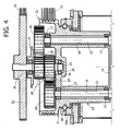
- a multigroove V-belt sheave 21 run over which is a number of endless drive belts 22, the cross section of which has a profile corresponding to that of the multigroove V-belt sheave 21 and each of which draws its motion from a pulley 23 ( Figures 1 - 3 ) actuated by the electric motor 5 with the interposition of a motor reducer 24.
- the planetary supporting structure 15 also supports a shaft 25 in such a way that it can turn about the central axis 11.
- the shaft 25 is mounted so that it can turn by means of bearings 26 at its bottom end above the wall 20 and at its top end above a wall 27 forming part of the planetary supporting structure 15.
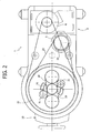
- Fitted on the shaft 25 are two coaxial pulleys 28 set axially on top of one another, each of which is connected, by means of a toothed belt 29 (see Figures 2 , 4 ), to a respective toothed pulley 30 fitted on the top end of the corresponding shaft 13 of a respective kneading implement 12.
- a belt-tensioning element 31 associated to each of the belts 29 is a belt-tensioning element 31.
- the shaft 25 carries, at its top end, a grooved pulley 32, which draws its motion from the electric motor 6 by means of V belts that engage the pulley 32, and a pulley 34 mounted on the output shaft of the motor 6.
- the tank 9 is prepared with the ingredients necessary for the dough and, in the case of the example illustrated, set in the operative position by engaging the carriage 10 to the fixed structure of the machine. Said operation is performed with the top head 8 in the raised condition. Then, the head is lowered so as to bring the kneading implements 12 down within the tank, and then the two motors 5, 6 are activated.
- the rotation of the motor 5 causes, as a result of the transmission consisting of the motor reducer 24, the belt 22, and the pulleys 23 and 21, rotation of the planetary structure 15.
- the kneading implements 12 thus perform with their axes an orbital movement about the central axis 11 of the tank.
- the motor 6 causes, via the transmission comprising the belt 33 and the pulleys 34 and 32, rotation of the shaft 25 and consequently rotation of the two pulleys 28.
- the latter transmit their rotation to the two kneading implements by means of the belts 29, so that said implements turn about their axes whilst they perform their orbital movement about the central axis 11 of the tank.
- All the means of transmission provided in the machine are lubricant-free so that the problem of a risk of contamination of the foodstuff that exists, instead, in machines equipped with gear transmissions is solved at the root.
- the structure of the machine is relatively simple and reliable, thanks in particular to the fact that the planetary structure 15 is supported in rotation about the central axis 11 in an area corresponding to its outer circumferential surface.
- Particularly advantageous is the provision of a single rolling bearing 18 for the purpose of supporting the planetary structure 15 so that it can turn.
- Figure 5 shows a detail of a preferred embodiment of the ball bearing 18, which comprises a series of balls that engage an inner ring 18c rotating with the planetary structure 15, and two outer rings 18a and 18b set on top of one another, screwed to the non-rotating structure of the head.
- a cylindrical casing 70 which is to engage within the tank 9 (see also Figures 1 , 3 ) for isolating the kneading environment from the external environment, in order to keep it above or below atmospheric pressure, according to the specific needs of the dough. In this case it is necessary to ensure pressure tightness within the kneading environment notwithstanding the fact that the planetary structure 15 is mounted so that it can turn with respect to the structure of the head 7.
- annular cavity 15b concentric with the axis 11 of rotation of the planetary structure, housed within which is an annular sealing gasket 51, which is also concentric with the axis 11.
- the gasket 51 has a front surface, orthogonal to the axis 11, co-operating in sliding contact with a surface 50a of the rotating structure 15.
- the chamber 52 defined between the bottom of the cavity 15b and the gasket 51 is in communication via channels 53 made in the plate 15a with an independent source of pressurized air (not illustrated), so that the gasket 51 is constantly pushed against the surface 50a.
- the rotation of the surface 50a with respect to the gasket 51 leads to the gasket progressively wearing out by friction. Consequently, the axial dimension of the gasket is progressively reduced, whilst the pressure in the chamber 52 always keeps the gasket itself in contact with the wall 50a.
Landscapes
- Life Sciences & Earth Sciences (AREA)
- Engineering & Computer Science (AREA)
- Food Science & Technology (AREA)
- Chemical & Material Sciences (AREA)
- Chemical Kinetics & Catalysis (AREA)
- Mixers Of The Rotary Stirring Type (AREA)
- Food-Manufacturing Devices (AREA)
- Preparation Of Clay, And Manufacture Of Mixtures Containing Clay Or Cement (AREA)
- Cereal-Derived Products (AREA)
Claims (12)
- Planetenknetmaschine für Lebensmittel, umfassend:einen Behälter (9);ein oder mehrere Knetwerkzeuge (12), die sich um jeweils vertikale Achsen (14) drehen können, welche in einem Abstand von einer vertikalen Mittelachse (11) angeordnet sind;eine Planetenkonstruktion (15) zum Stützen der Knetwerkzeuge (12), auf der jedes Knetwerkzeug (12) so angebracht ist, dass es sich um seine eigene Achse (14) drehen kann, wobei die Planeten-Stützkonstruktion (15) wiederum so angebracht ist, dass sie sich um die Mittelachse (11) des Behälters (9) auf einer Stützkonstruktion (7) der Maschine (1) drehen kann;erste Mittel zum Steuern einer Rotation der Planetenkonstruktion (15) um die Mittelachse (11) des Behälters (9); undzweite Mittel zum Steuern einer Rotation jedes Knetwerkzeugs (12) um seine eigene Achse (14),wobei die ersten Steuermittel und die zweiten Steuermittel einen ersten Elektromotor (5) und einen zweiten Elektromotor (6) umfassen und eine erste Transmission (21-23), die den ersten Elektromotor (5) mit der vorgenannten Planetenkonstruktion (15) verbindet, und eine zweite Transmission (34, 33, 32, 25, 28, 29, 30), die den zweiten Elektromotor (6) mit jedem Knetwerkzeug, das sich drehen kann (12), verbindet, und wobei jeder der ersten und der zweiten Transmissionen schmiermittelfrei ist und vorzugsweise von einer Art ist, die ein oder mehrere endlose Übertragungselemente (22, 33, 29) aufweist,
dadurch gekennzeichnet, dass das endlose Übertragungselement ein Riemen ist, und dass die Planetenkonstruktion (15) einen Körper aufweist, der drehbar die Werkzeuge (12) um ihre Achsen (14) stützt, wobei der Körper eine umlaufende Außenfläche aufweist und drehbar um die Mittelachse (11) von der Stützkonstruktion (7) der Maschine durch ein Wälzlager (18), welches sich auf der umlaufenden Außenfläche befindet, radial auf der Außenseite in Bezug auf die Achsen (14) der Werkzeuge (12), gestützt ist. - Knetmaschine nach Anspruch 1, dadurch gekennzeichnet, das das endlose Übertragungselement ein Zahnriemen ist.
- Knetmaschine nach Anspruch 1, dadurch gekennzeichnet, dass sie ein einzelnes Wälzlager (18) zum Stützen der Planetenkonstruktion (15) umfasst, das einen äußeren Ring aufweist, der von der tragenden Konstruktion (7) getragen wird und dafür ausgelegt ist, das Gewicht der Planetenkonstruktion (15) zu halten.
- Knetmaschine nach Anspruch 3, dadurch gekennzeichnet, dass das einzelne Wälzlager den Innenring zum Eingreifen der Wälzkörper direkt in der umlaufenden Außenfläche der Planetenkonstruktion (15) ausbildet.
- Knetmaschine nach Anspruch 1, dadurch gekennzeichnet, dass die Planetenkonstruktion (15) eine Riemenscheibe (21) zum Eingreifen in einen endlosen Antriebsriemen (22), der seine Bewegung von einer Riemenscheibe (23) bezieht, die von dem ersten Elektromotor (5) bewegt ist.
- Knetmaschine nach Anspruch 1, dadurch gekennzeichnet, dass die Planetenkonstruktion (15) umfangsseitig eine Reihe zylindrischer Hohlräume (16) aufweist, innerhalb derer vertikale, drehbare Schäfte angebracht sind (13), von denen jeder jeweils ein Knetwerkzeug (12) trägt.
- Knetmaschine nach Anspruch 6, dadurch gekennzeichnet, dass jeder der Schäfte eine Riemenscheibe (30) trägt, die über einen Riemenantrieb mit dem zweiten Elektromotor (6) verbunden ist.
- Knetmaschine nach Anspruch 7, dadurch gekennzeichnet, dass die Riemenscheiben, die von den Schäften (13) der Knetwerkzeuge (12) getragen werden, über jeweilige Riemenantriebe (29) mit zwei koaxialen Riemenscheiben (28) verbunden sind, die axial übereinander auf einem Schaft (25) montiert sind, der so gestützt ist, dass er durch die Planetenkonstruktion (15) um die vorgenannte Mittelachse (11) gedreht werden kann, wobei der Schaft (25) eine weitere Riemenscheibe (32) trägt, die über einen Riemenantrieb (32, 33, 34) von dem zweiten Elektromotor (6) bewegt wird.
- Knetmaschine nach Anspruch 1, dadurch gekennzeichnet, dass die Planetenkonstruktion (15) mit einer Dichtung (51) versehen ist, die von der feststehenden Konstruktion (7) der Maschine getragen wird, um die Knetumgebung von der äußeren Umgebung zu isolieren, damit die Knetumgebung bei einem Druck gehalten werden kann, der sich von dem atmosphärischen Druck unterscheidet.
- Knetmaschine nach Anspruch 9, dadurch gekennzeichnet, dass die Dichtung (51) ein ringförmiges Element ist, das konzentrisch in Bezug auf die Rotationsachse (11) der Planetenkonstruktion eingesetzt ist und senkrecht zu der Achse (11) eine vordere Dichtfläche aufweist, die mit einer ihr gegenüberliegenden Fläche (50a) zusammenwirkt, die an der Planetenkonstruktion (15) feststehend ist.
- Knetmaschine nach Anspruch 9, dadurch gekennzeichnet, dass die Dichtung (51) derart angebracht ist, dass sie axial in einer ringförmigen Ausnehmung (15b) eines Elements (15a), das fest mit der Struktur des Kopfendes (7) verbunden ist, gleiten kann, und dass sie einem Druck ausgesetzt ist, der von einer unabhängigen Druckquelle ausgeübt wird, die versucht, sie gegen die zusammenwirkende Fläche (50a) der Planetenkonstruktion (15) zu drücken.
- Knetmaschine nach Anspruch 11, dadurch gekennzeichnet, dass die Dichtung (51) aus Kunststoff, vorzugsweise PTFE, hergestellt ist.
Applications Claiming Priority (1)
| Application Number | Priority Date | Filing Date | Title |
|---|---|---|---|
| IT000892A ITTO20040892A1 (it) | 2004-12-21 | 2004-12-21 | Macchina impastatrice planetaria per impasti alimentari |
Publications (2)
| Publication Number | Publication Date |
|---|---|
| EP1676629A1 EP1676629A1 (de) | 2006-07-05 |
| EP1676629B1 true EP1676629B1 (de) | 2008-06-25 |
Family
ID=36029174
Family Applications (1)
| Application Number | Title | Priority Date | Filing Date |
|---|---|---|---|
| EP05106652A Expired - Lifetime EP1676629B1 (de) | 2004-12-21 | 2005-07-20 | Knetmaschine mit Planetengetriebe zur Verarbeitung von Lebensmitteln |
Country Status (4)
| Country | Link |
|---|---|
| EP (1) | EP1676629B1 (de) |
| AT (1) | ATE399053T1 (de) |
| DE (1) | DE602005007695D1 (de) |
| IT (1) | ITTO20040892A1 (de) |
Families Citing this family (4)
| Publication number | Priority date | Publication date | Assignee | Title |
|---|---|---|---|---|
| EP1969943A1 (de) | 2007-03-16 | 2008-09-17 | SANCASSIANO S.p.A. | Knetmaschine für Lebensmittel |
| RU2333404C1 (ru) * | 2007-03-26 | 2008-09-10 | Государственное образовательное учреждение высшего профессионального образования "Петербургский государственный университет путей сообщения" | Планетарный механизм |
| IT1391902B1 (it) * | 2008-11-12 | 2012-01-27 | Domino S R L | Macchina impastatrice perfezionata |
| CN110881489B (zh) * | 2019-12-25 | 2021-04-06 | 河南职业技术学院 | 一种层叠式仿人工揉面装置 |
Family Cites Families (9)
| Publication number | Priority date | Publication date | Assignee | Title |
|---|---|---|---|---|
| DE572800C (de) * | ||||
| US4132484A (en) * | 1974-06-11 | 1979-01-02 | Hans Kimmel | Mixer, particularly heating-cooling mixer for chemical processes |
| ES478241A1 (es) * | 1978-02-15 | 1980-01-01 | Baker Perkins Holdings Ltd | Maquina elaboradora para el tratamiento de productos, espe- cialmente en forma pastosa y metodo correspondiente. |
| DE2831686A1 (de) * | 1978-07-19 | 1980-02-07 | Eckhard Schulz | Mischmaschine |
| US4697929A (en) * | 1986-10-28 | 1987-10-06 | Charles Ross & Son Company | Planetary mixers |
| DE4118794A1 (de) * | 1991-06-07 | 1992-12-10 | Mti Mischtechnik Industrieanla | Vertikal-pastenmischer |
| CH686933A5 (de) * | 1992-04-15 | 1996-08-15 | Fischer Georg Giessereianlagen | Vorrichtung zum Mischen und Aufbereiten von rieselfaehigen Materialien. |
| GB2355415A (en) * | 1999-10-22 | 2001-04-25 | Augusts Ltd | Pan mixer having independently driven planetary mixing tools |
| DE10012072B4 (de) * | 2000-03-14 | 2015-08-27 | Hermann Linden Gmbh & Co. Kg | Inline Mischer |
-
2004
- 2004-12-21 IT IT000892A patent/ITTO20040892A1/it unknown
-
2005
- 2005-07-20 EP EP05106652A patent/EP1676629B1/de not_active Expired - Lifetime
- 2005-07-20 DE DE602005007695T patent/DE602005007695D1/de not_active Expired - Lifetime
- 2005-07-20 AT AT05106652T patent/ATE399053T1/de not_active IP Right Cessation
Also Published As
| Publication number | Publication date |
|---|---|
| ITTO20040892A1 (it) | 2005-03-21 |
| EP1676629A1 (de) | 2006-07-05 |
| DE602005007695D1 (de) | 2008-08-07 |
| ATE399053T1 (de) | 2008-07-15 |
Similar Documents
| Publication | Publication Date | Title |
|---|---|---|
| US6733375B2 (en) | Horizontal finishing machine | |
| CN102834647B (zh) | 用于冲压压力机的传动单元和装置 | |
| KR101933118B1 (ko) | 감속기용 누유방지 구조 | |
| US4007560A (en) | Two wheel lapping machine | |
| US9879771B2 (en) | Dry well shaft assembly | |
| EP1676629B1 (de) | Knetmaschine mit Planetengetriebe zur Verarbeitung von Lebensmitteln | |
| US2795155A (en) | Speed reducers | |
| CN117366216B (zh) | 一种行星减速机齿轮润滑机构 | |
| EP1696111A3 (de) | Vorrichtung zum Übertragen der Drehbewegung zu einer Antriebsachse, insbesondere für Flüssigkeitspumpen | |
| US9982753B1 (en) | Housing-rotatable planetary gear reducer for stand mixer | |
| US20060178093A1 (en) | High speed vertical processor | |
| US7516695B2 (en) | Press machine | |
| EP3228903B1 (de) | Vorrichtung zur übertragung der rotationsleistung, maschine mit solch einer vorrichtung und verwendung solch einer vorrichtung | |
| SE468167B (sv) | Anordning foer utmatning av partikelformigt material | |
| RU2513380C2 (ru) | Кухонный прибор с планетарной передачей | |
| CN117899698B (zh) | 一种护肤手套生产用溶剂制备装置 | |
| JP3158312B2 (ja) | 缶成形装置 | |
| CN219193367U (zh) | 一种磁力轮输送机 | |
| US5352150A (en) | Feeding device installed in a loading bin, for special use in a sausage filling machine | |
| US10760673B2 (en) | Planetary roller transmission | |
| CN218753140U (zh) | 一种无油高密封性的自动上甄机 | |
| CN222415686U (zh) | 一种轴承座组件和用于栽培食用菌的高温灭菌器 | |
| CN210580835U (zh) | 一种食品药品高温高压杀菌设备 | |
| CN113562661A (zh) | 一种内置式旋升装置 | |
| CN206280447U (zh) | 一种花键联动定位传动机构及设有该机构的蔬菜脱水机 |
Legal Events
| Date | Code | Title | Description |
|---|---|---|---|
| PUAI | Public reference made under article 153(3) epc to a published international application that has entered the european phase |
Free format text: ORIGINAL CODE: 0009012 |
|
| AK | Designated contracting states |
Kind code of ref document: A1 Designated state(s): AT BE BG CH CY CZ DE DK EE ES FI FR GB GR HU IE IS IT LI LT LU LV MC NL PL PT RO SE SI SK TR |
|
| AX | Request for extension of the european patent |
Extension state: AL BA HR MK YU |
|
| 17P | Request for examination filed |
Effective date: 20060704 |
|
| 17Q | First examination report despatched |
Effective date: 20060728 |
|
| AKX | Designation fees paid |
Designated state(s): AT BE BG CH CY CZ DE DK EE ES FI FR GB GR HU IE IS IT LI LT LU LV MC NL PL PT RO SE SI SK TR |
|
| GRAP | Despatch of communication of intention to grant a patent |
Free format text: ORIGINAL CODE: EPIDOSNIGR1 |
|
| GRAS | Grant fee paid |
Free format text: ORIGINAL CODE: EPIDOSNIGR3 |
|
| GRAA | (expected) grant |
Free format text: ORIGINAL CODE: 0009210 |
|
| AK | Designated contracting states |
Kind code of ref document: B1 Designated state(s): AT BE BG CH CY CZ DE DK EE ES FI FR GB GR HU IE IS IT LI LT LU LV MC NL PL PT RO SE SI SK TR |
|
| REG | Reference to a national code |
Ref country code: GB Ref legal event code: FG4D |
|
| REG | Reference to a national code |
Ref country code: CH Ref legal event code: EP |
|
| REF | Corresponds to: |
Ref document number: 602005007695 Country of ref document: DE Date of ref document: 20080807 Kind code of ref document: P |
|
| REG | Reference to a national code |
Ref country code: IE Ref legal event code: FG4D |
|
| PG25 | Lapsed in a contracting state [announced via postgrant information from national office to epo] |
Ref country code: FI Free format text: LAPSE BECAUSE OF FAILURE TO SUBMIT A TRANSLATION OF THE DESCRIPTION OR TO PAY THE FEE WITHIN THE PRESCRIBED TIME-LIMIT Effective date: 20080625 Ref country code: SI Free format text: LAPSE BECAUSE OF FAILURE TO SUBMIT A TRANSLATION OF THE DESCRIPTION OR TO PAY THE FEE WITHIN THE PRESCRIBED TIME-LIMIT Effective date: 20080625 |
|
| PG25 | Lapsed in a contracting state [announced via postgrant information from national office to epo] |
Ref country code: NL Free format text: LAPSE BECAUSE OF FAILURE TO SUBMIT A TRANSLATION OF THE DESCRIPTION OR TO PAY THE FEE WITHIN THE PRESCRIBED TIME-LIMIT Effective date: 20080625 Ref country code: PL Free format text: LAPSE BECAUSE OF FAILURE TO SUBMIT A TRANSLATION OF THE DESCRIPTION OR TO PAY THE FEE WITHIN THE PRESCRIBED TIME-LIMIT Effective date: 20080625 Ref country code: LV Free format text: LAPSE BECAUSE OF FAILURE TO SUBMIT A TRANSLATION OF THE DESCRIPTION OR TO PAY THE FEE WITHIN THE PRESCRIBED TIME-LIMIT Effective date: 20080625 Ref country code: AT Free format text: LAPSE BECAUSE OF FAILURE TO SUBMIT A TRANSLATION OF THE DESCRIPTION OR TO PAY THE FEE WITHIN THE PRESCRIBED TIME-LIMIT Effective date: 20080625 |
|
| NLV1 | Nl: lapsed or annulled due to failure to fulfill the requirements of art. 29p and 29m of the patents act | ||
| PG25 | Lapsed in a contracting state [announced via postgrant information from national office to epo] |
Ref country code: SE Free format text: LAPSE BECAUSE OF FAILURE TO SUBMIT A TRANSLATION OF THE DESCRIPTION OR TO PAY THE FEE WITHIN THE PRESCRIBED TIME-LIMIT Effective date: 20080925 Ref country code: IS Free format text: LAPSE BECAUSE OF FAILURE TO SUBMIT A TRANSLATION OF THE DESCRIPTION OR TO PAY THE FEE WITHIN THE PRESCRIBED TIME-LIMIT Effective date: 20081025 Ref country code: LT Free format text: LAPSE BECAUSE OF FAILURE TO SUBMIT A TRANSLATION OF THE DESCRIPTION OR TO PAY THE FEE WITHIN THE PRESCRIBED TIME-LIMIT Effective date: 20080625 |
|
| PG25 | Lapsed in a contracting state [announced via postgrant information from national office to epo] |
Ref country code: SK Free format text: LAPSE BECAUSE OF FAILURE TO SUBMIT A TRANSLATION OF THE DESCRIPTION OR TO PAY THE FEE WITHIN THE PRESCRIBED TIME-LIMIT Effective date: 20080625 Ref country code: BE Free format text: LAPSE BECAUSE OF FAILURE TO SUBMIT A TRANSLATION OF THE DESCRIPTION OR TO PAY THE FEE WITHIN THE PRESCRIBED TIME-LIMIT Effective date: 20080625 Ref country code: ES Free format text: LAPSE BECAUSE OF FAILURE TO SUBMIT A TRANSLATION OF THE DESCRIPTION OR TO PAY THE FEE WITHIN THE PRESCRIBED TIME-LIMIT Effective date: 20081006 Ref country code: PT Free format text: LAPSE BECAUSE OF FAILURE TO SUBMIT A TRANSLATION OF THE DESCRIPTION OR TO PAY THE FEE WITHIN THE PRESCRIBED TIME-LIMIT Effective date: 20081125 Ref country code: RO Free format text: LAPSE BECAUSE OF FAILURE TO SUBMIT A TRANSLATION OF THE DESCRIPTION OR TO PAY THE FEE WITHIN THE PRESCRIBED TIME-LIMIT Effective date: 20080625 |
|
| PG25 | Lapsed in a contracting state [announced via postgrant information from national office to epo] |
Ref country code: MC Free format text: LAPSE BECAUSE OF NON-PAYMENT OF DUE FEES Effective date: 20080731 |
|
| REG | Reference to a national code |
Ref country code: IE Ref legal event code: MM4A |
|
| PG25 | Lapsed in a contracting state [announced via postgrant information from national office to epo] |
Ref country code: EE Free format text: LAPSE BECAUSE OF FAILURE TO SUBMIT A TRANSLATION OF THE DESCRIPTION OR TO PAY THE FEE WITHIN THE PRESCRIBED TIME-LIMIT Effective date: 20080625 Ref country code: BG Free format text: LAPSE BECAUSE OF FAILURE TO SUBMIT A TRANSLATION OF THE DESCRIPTION OR TO PAY THE FEE WITHIN THE PRESCRIBED TIME-LIMIT Effective date: 20080925 Ref country code: DK Free format text: LAPSE BECAUSE OF FAILURE TO SUBMIT A TRANSLATION OF THE DESCRIPTION OR TO PAY THE FEE WITHIN THE PRESCRIBED TIME-LIMIT Effective date: 20080625 |
|
| PLBE | No opposition filed within time limit |
Free format text: ORIGINAL CODE: 0009261 |
|
| STAA | Information on the status of an ep patent application or granted ep patent |
Free format text: STATUS: NO OPPOSITION FILED WITHIN TIME LIMIT |
|
| 26N | No opposition filed |
Effective date: 20090326 |
|
| PG25 | Lapsed in a contracting state [announced via postgrant information from national office to epo] |
Ref country code: IE Free format text: LAPSE BECAUSE OF NON-PAYMENT OF DUE FEES Effective date: 20080720 |
|
| REG | Reference to a national code |
Ref country code: CH Ref legal event code: PL |
|
| GBPC | Gb: european patent ceased through non-payment of renewal fee |
Effective date: 20090720 |
|
| PG25 | Lapsed in a contracting state [announced via postgrant information from national office to epo] |
Ref country code: CH Free format text: LAPSE BECAUSE OF NON-PAYMENT OF DUE FEES Effective date: 20090731 Ref country code: LI Free format text: LAPSE BECAUSE OF NON-PAYMENT OF DUE FEES Effective date: 20090731 |
|
| PG25 | Lapsed in a contracting state [announced via postgrant information from national office to epo] |
Ref country code: GB Free format text: LAPSE BECAUSE OF NON-PAYMENT OF DUE FEES Effective date: 20090720 |
|
| PG25 | Lapsed in a contracting state [announced via postgrant information from national office to epo] |
Ref country code: HU Free format text: LAPSE BECAUSE OF FAILURE TO SUBMIT A TRANSLATION OF THE DESCRIPTION OR TO PAY THE FEE WITHIN THE PRESCRIBED TIME-LIMIT Effective date: 20081226 Ref country code: LU Free format text: LAPSE BECAUSE OF NON-PAYMENT OF DUE FEES Effective date: 20080720 Ref country code: CY Free format text: LAPSE BECAUSE OF FAILURE TO SUBMIT A TRANSLATION OF THE DESCRIPTION OR TO PAY THE FEE WITHIN THE PRESCRIBED TIME-LIMIT Effective date: 20080625 |
|
| PG25 | Lapsed in a contracting state [announced via postgrant information from national office to epo] |
Ref country code: TR Free format text: LAPSE BECAUSE OF FAILURE TO SUBMIT A TRANSLATION OF THE DESCRIPTION OR TO PAY THE FEE WITHIN THE PRESCRIBED TIME-LIMIT Effective date: 20080625 |
|
| PG25 | Lapsed in a contracting state [announced via postgrant information from national office to epo] |
Ref country code: GR Free format text: LAPSE BECAUSE OF FAILURE TO SUBMIT A TRANSLATION OF THE DESCRIPTION OR TO PAY THE FEE WITHIN THE PRESCRIBED TIME-LIMIT Effective date: 20080926 |
|
| REG | Reference to a national code |
Ref country code: FR Ref legal event code: PLFP Year of fee payment: 12 |
|
| PGFP | Annual fee paid to national office [announced via postgrant information from national office to epo] |
Ref country code: CZ Payment date: 20160713 Year of fee payment: 12 |
|
| REG | Reference to a national code |
Ref country code: FR Ref legal event code: PLFP Year of fee payment: 13 |
|
| PG25 | Lapsed in a contracting state [announced via postgrant information from national office to epo] |
Ref country code: CZ Free format text: LAPSE BECAUSE OF NON-PAYMENT OF DUE FEES Effective date: 20170720 |
|
| REG | Reference to a national code |
Ref country code: FR Ref legal event code: PLFP Year of fee payment: 14 |
|
| REG | Reference to a national code |
Ref country code: DE Ref legal event code: R079 Ref document number: 602005007695 Country of ref document: DE Free format text: PREVIOUS MAIN CLASS: B01F0007300000 Ipc: B01F0027950000 |
|
| PGFP | Annual fee paid to national office [announced via postgrant information from national office to epo] |
Ref country code: DE Payment date: 20240730 Year of fee payment: 20 |
|
| PGFP | Annual fee paid to national office [announced via postgrant information from national office to epo] |
Ref country code: FR Payment date: 20240725 Year of fee payment: 20 |
|
| PGFP | Annual fee paid to national office [announced via postgrant information from national office to epo] |
Ref country code: IT Payment date: 20240705 Year of fee payment: 20 |
|
| REG | Reference to a national code |
Ref country code: DE Ref legal event code: R071 Ref document number: 602005007695 Country of ref document: DE |