EP1676642A1 - Procédé de revêtement et un ecran pour un composant - Google Patents
Procédé de revêtement et un ecran pour un composant Download PDFInfo
- Publication number
- EP1676642A1 EP1676642A1 EP06250023A EP06250023A EP1676642A1 EP 1676642 A1 EP1676642 A1 EP 1676642A1 EP 06250023 A EP06250023 A EP 06250023A EP 06250023 A EP06250023 A EP 06250023A EP 1676642 A1 EP1676642 A1 EP 1676642A1
- Authority
- EP
- European Patent Office
- Prior art keywords
- shield
- edge
- component
- recited
- airfoil
- Prior art date
- Legal status (The legal status is an assumption and is not a legal conclusion. Google has not performed a legal analysis and makes no representation as to the accuracy of the status listed.)
- Granted
Links
Images


Classifications
-
- C—CHEMISTRY; METALLURGY
- C25—ELECTROLYTIC OR ELECTROPHORETIC PROCESSES; APPARATUS THEREFOR
- C25D—PROCESSES FOR THE ELECTROLYTIC OR ELECTROPHORETIC PRODUCTION OF COATINGS; ELECTROFORMING; APPARATUS THEREFOR
- C25D5/00—Electroplating characterised by the process; Pretreatment or after-treatment of workpieces
- C25D5/02—Electroplating of selected surface areas
- C25D5/022—Electroplating of selected surface areas using masking means
-
- B—PERFORMING OPERATIONS; TRANSPORTING
- B05—SPRAYING OR ATOMISING IN GENERAL; APPLYING FLUENT MATERIALS TO SURFACES, IN GENERAL
- B05B—SPRAYING APPARATUS; ATOMISING APPARATUS; NOZZLES
- B05B12/00—Arrangements for controlling delivery; Arrangements for controlling the spray area
- B05B12/16—Arrangements for controlling delivery; Arrangements for controlling the spray area for controlling the spray area
- B05B12/20—Masking elements, i.e. elements defining uncoated areas on an object to be coated
Definitions
- the present invention relates generally to a method of coating and a shield for a component.
- the present invention relates to a photochemical edge shield that protects, for example, cooling slots of a vane of a gas turbine engine during a ceramic coating process.
- a gas turbine engine includes alternating rows of rotary airfoils or blades and stationary airfoils or vanes. Each vane includes cooling slots that allow air to enter and cool the vane during use.
- the vanes are usually made of nickel superalloy and are commonly coated with a ceramic coating to provide a thermal barrier.
- a shield has been employed to cover the cooling slots and prevent the ceramic coating from entering the cooling slots during ceramic coating process.
- the shield of the prior art includes two projections that each fit into a corresponding slot in the airfoil to locate the shield relative to the airfoil. The projections are located at opposite ends of the shield, and a curved edge extends between the projections.
- the airfoil is also commonly masked before coating to prevent the coating from flowing into the cooling slots.
- a grit blasting step is then employed after coating to remove any ceramic residue in the cooling slots.
- a drawback to conventional shields is that the ceramic coating can leak around the shield and possibly flow into the cooling slots. Additionally, the steps of masking and grit blasting are costly. Finally, the shield does not include any feature to secure the shield relative to the airfoil.
- a gas turbine engine is used for power generation or propulsion.
- the gas turbine engine includes altemating rows of rotary airfoils or blades and static airfoils or vanes.
- Each vane includes a trailing edge having a curvature and cooling slots. During use, the vane becomes very hot, and the cooling slots allow air to enter and cool the vane.
- the vane is made of a nickel superalloy and is coated with a ceramic coating to provide a thermal barrier.
- a photochemical edge shield is positioned on the vane before the ceramic coating process to prevent the ceramic coating from flowing into and clogging the cooling slots.
- the photochemical edge shield includes an edge having a curvature and projections that project from the edge.
- the edge of the photochemical edge shield has substantially the same shape and curvature as the trailing edge of the vane.
- the number of projections is equal to the number of cooling slots.
- a top surface of the photochemical edge shield is substantially planar and flat, and a bottom surface of the photochemical edge shield includes a recessed edge.
- the curvature of the recessed edge is approximately equal to the curvature of the edge of the photochemical edge shield.
- a recessed space defined between the each of the projections extends between the edge and the recessed edge.
- the photochemical edge also includes a fold over flap separated from a body by a fold line having a reduced thickness.
- the photochemical edge shield is positioned on the vane such that the bottom surface contacts the vane and each of the projections is received in one of the cooling slots.
- the photochemical edge shield is then bent at the fold line such that the fold over flap is located under the vane.
- the photochemical edge shield is then tack welded to secure the photochemical edge shield to the vane. After the ceramic coating process is completed, the photochemical edge shield is removed from the vane.
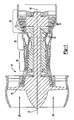
- FIG. 1 schematically illustrates a gas turbine engine 10 used for power generation or propulsion.
- the gas turbine engine 10 includes an axial centerline 12, a fan 14, a compressor section 16, a combustion section 18 and a turbine 20. Air compressed in the compressor section 16 is mixed with fuel, burned in the combustion section 18 and expanded in the turbine 20. The air compressed in the compressor section 16 and the fuel mixture expanded in the turbine 20 are both referred to as a hot gas stream flow 28.
- Rotors 22 of the turbine 20 rotate in response to the expansion and drive the compressor section 16 and the fan 14.
- the turbine 20 also includes alternating rows of rotary airfoils or blades 24 on the rotors 22 and static airfoils or vanes 27.
- the vanes 27 could be made of a base metal of nickel superalloy.
- FIG. 2 illustrates a portion of a vane assembly.
- the vane assembly can include an airfoil section 26 extending between one or more platforms 25.
- the vane assembly includes one or more interior passageways (not shown).
- the airfoil section 26 includes a trailing edge 30 having a curvature and cooling slots 32 on the pressure side of the airfoil section 26.
- the cooling slots 32 communicate with the interior passageways.
- Each cooling slot 32 is separated by a wall 56.
- a back edge 29 is located behind the cooling slots 32.
- Bleed air typically drawn from the relatively cooler compressor section 16
- the cooling slots 32 allow the bleed air within the interior passageways to exit the vane assembly and to merge with the core airflow.
- the gas path section of the airfoil section 26 is coated with a ceramic coating to provide a thermal barrier.
- the ceramic coating has a low thermal conductivity and provides heat protection. During application of the ceramic coating, whether during original manufacture or during a subsequent repair operation, the cooling slots 32 can become clogged.
- FIGS 3 and 4 illustrate a photochemical edge shield 34 that is positioned on the airfoil section 26 to protect the cooling slots 32 during the ceramic coating process and to prevent the ceramic coating from flowing into and clogging the cooling slots 32.
- a photochemical shield is meant a shield which is formed photochemically or by a photochemical process.
- a shield in accordance with the invention may be formed by any suitable method.
- the photochemical edge shield 34 includes a body 48 having an edge 36 that conforms to the shape of the airfoil section 26 of the vane assembly. Specifically, the edge 36 of the photochemical edge shield 34 is curved since the trailing edge 30 of the airfoil section 26 is curved
- the body 48 also includes projections 38 extending from the edge 36.
- Each of the projections 38 corresponds to a respective cooling slot 32 in the airfoil section 26. Accordingly, each projection 38 conforms to the shape of the respective cooling slot 32.
- the ends of each projection 38 could be substantially curved or semicircular in shape.
- a locating arm 40 on each end of the photochemical edge shield 34 inserts into an opening 58 in the airfoil section 26 to ensure that the photochemical edge shield 34 is properly aligned with the airfoil section 26.
- the photochemical edge shield 34 can be made of various materials.
- the photochemical edge shield 34 can be made of stainless steel, brass or copper.
- the photochemical edge shield 34 can be made of any material, and one skilled in the art would know what materials to employ.
- a top surface 41 of the photochemical edge shield 34 could be substantially planar, continuous and flat That is, the top surface 41 does not include any recessed spaces.
- the bottom surface 44 of the photochemical edge shield 34 includes a recessed edge 46. The curvature of the recessed edge 46 is approximately equal to the curvature of the edge 36.
- a recessed space 50 is defined between adjacent projections 38, and each recessed space 50 extends between the edge 36 and the recessed edge 46.
- each recessed space 50 has a thickness x
- the body 48 and the projections 38 of the photochemical edge shield 34 have a thickness y, which is greater than the thickness x.
- the photochemical edge shield 34 has a constant thickness and no recessed portions between the projections 38.
- the photochemical edge shield 34 can also include a fold line 60 having a reduced thickness that separates the body 48 from a fold over flap 42.
- the photochemical edge shield 34 can also include one or more holes 52 that allow a fixture (not shown) to help position the photochemical edge shield 34 on the airfoil section 26 of the vane assembly before the ceramic coating process begins.
- the fixture can help control the depth that the projections 38 enter the cooling slots 32 of the airfoil section 26.
- the photochemical edge shield 34 is positioned on the airfoil section 26 as shown in Figure 6 such that each of the projections 38 is received in a corresponding one of the cooling slots 32.
- Each recessed space 50 receives a corresponding one of the walls 56 that are between each of the cooling slots 32.
- the locating arms 40 locate the photochemical edge shield 34 relative to the airfoil section 26.
- the photochemical edge shield 34 is bent along the fold line 60 such that the fold over flap 42 is bent around the trailing edge 30 of the airfoil section 26 to reside on the suction side of the airfoil section 26, as shown in Figure 6.
- the body 48 of the photochemical edge shield 34 and the fold over flap 44 can be separate components.
- the photochemical edge shield 34 is then secured to the airfoil section 26 to prevent distortion during the ceramic coating process.
- the photochemical edge shield 34 can be secured to the airfoil section 26 by tack welding. Three to five tack welds can be employed.
- the photochemical edge shield 34 can include tabs in the body 48 that can be bent inwardly to contact the airfoil section 26 and to secure the photochemical edge shield 34 to the airfoil section 26.
- any method can be used to secure the photochemical edge shield 34 to the airfoil section 26, and one skilled in the art could select which technique to use.
- a sprayer 54 applies the ceramic coating to the airfoil section 26 using, for example, conventional techniques.
- the projections 38 of the photochemical edge shield 34 received in the cooling slots 32 prevent the ceramic coating from entering and clogging the cooling slots 32.
- the contact of the recessed edge 46 of the photochemical edge shield 34 and the trailing edge 30 of the airfoil section 26 and the contact of the edge 36 of the photochemical edge shield 34 and the back edge 29 of the airfoil section 26 also provide a seal that further prevents the ceramic coating from entering the cooling slots 32. Therefore, an additional masking and grit blasting step is not needed to remove the ceramic coating from the cooling slots 32.
- the photochemical edge shield 34 is removed from the airfoil section 26.
- the fixture engages the holes 52 to remove the photochemical edge shield 34 from the airfoil section 26.
- the coating process of the present invention is less expensive than the prior art technique because the masking and grit blasting steps are not needed.
- the photochemical edge shield 34 can also be coated with a coating to prevent the ceramic coating from adhering to the photochemical edge shield 34 and to prevent flaking.
- a coating of titanium dioxide is applied to the photochemical edge shield 34 to prevent the ceramic coating from adhering to the photochemical edge shield 34.
- the airfoil section 126 can include a trailing edge 130 with a reverse curvature.
- the photochemical edge shield 134 also has an edge 136 with a reverse curvature. That is, the curvatures of the trailing edge 130 and the edge 136 are substantially equal.
Landscapes
- Chemical & Material Sciences (AREA)
- Engineering & Computer Science (AREA)
- Chemical Kinetics & Catalysis (AREA)
- Electrochemistry (AREA)
- Materials Engineering (AREA)
- Metallurgy (AREA)
- Organic Chemistry (AREA)
- Turbine Rotor Nozzle Sealing (AREA)
Priority Applications (1)
| Application Number | Priority Date | Filing Date | Title |
|---|---|---|---|
| EP10005981.5A EP2226128B1 (fr) | 2005-01-04 | 2006-01-04 | Procédé de revêtement et un écran pour un composant |
Applications Claiming Priority (1)
| Application Number | Priority Date | Filing Date | Title |
|---|---|---|---|
| US11/028,880 US7510375B2 (en) | 2005-01-04 | 2005-01-04 | Method of coating and a shield for a component |
Related Child Applications (2)
| Application Number | Title | Priority Date | Filing Date |
|---|---|---|---|
| EP10005981.5A Division EP2226128B1 (fr) | 2005-01-04 | 2006-01-04 | Procédé de revêtement et un écran pour un composant |
| EP10005981.5 Division-Into | 2010-06-10 |
Publications (2)
| Publication Number | Publication Date |
|---|---|
| EP1676642A1 true EP1676642A1 (fr) | 2006-07-05 |
| EP1676642B1 EP1676642B1 (fr) | 2011-07-20 |
Family
ID=36097011
Family Applications (2)
| Application Number | Title | Priority Date | Filing Date |
|---|---|---|---|
| EP10005981.5A Expired - Lifetime EP2226128B1 (fr) | 2005-01-04 | 2006-01-04 | Procédé de revêtement et un écran pour un composant |
| EP06250023A Expired - Lifetime EP1676642B1 (fr) | 2005-01-04 | 2006-01-04 | Appareil et procédé pour la protection des rainures de refroidissement d'une ailette pendant le revêtement |
Family Applications Before (1)
| Application Number | Title | Priority Date | Filing Date |
|---|---|---|---|
| EP10005981.5A Expired - Lifetime EP2226128B1 (fr) | 2005-01-04 | 2006-01-04 | Procédé de revêtement et un écran pour un composant |
Country Status (3)
| Country | Link |
|---|---|
| US (2) | US7510375B2 (fr) |
| EP (2) | EP2226128B1 (fr) |
| JP (1) | JP4283270B2 (fr) |
Cited By (2)
| Publication number | Priority date | Publication date | Assignee | Title |
|---|---|---|---|---|
| EP2053142A3 (fr) * | 2007-10-24 | 2012-01-25 | United Technologies Corporation | Procédé de vaporisation d'un composant de moteur à turbine |
| CN103882360A (zh) * | 2014-03-26 | 2014-06-25 | 哈尔滨东安发动机(集团)有限公司 | 热喷涂表面通孔的防护方法 |
Families Citing this family (15)
| Publication number | Priority date | Publication date | Assignee | Title |
|---|---|---|---|---|
| EP1820873A1 (fr) * | 2006-01-17 | 2007-08-22 | Siemens Aktiengesellschaft | Procédé de fabrication des composants de turbine |
| US8967078B2 (en) * | 2009-08-27 | 2015-03-03 | United Technologies Corporation | Abrasive finish mask and method of polishing a component |
| US20110171390A1 (en) * | 2010-01-08 | 2011-07-14 | United Technologies Corporation One Financial Plaza | Fixture for coating application |
| EP2362068A1 (fr) * | 2010-02-19 | 2011-08-31 | Siemens Aktiengesellschaft | Aube de turbine |
| EP2418357A1 (fr) | 2010-08-05 | 2012-02-15 | Siemens Aktiengesellschaft | Aube de turbine et procédé pour revêtement de la barrière thermique |
| US10100650B2 (en) * | 2012-06-30 | 2018-10-16 | General Electric Company | Process for selectively producing thermal barrier coatings on turbine hardware |
| US9181809B2 (en) | 2012-12-04 | 2015-11-10 | General Electric Company | Coated article |
| US11035249B2 (en) * | 2014-07-23 | 2021-06-15 | Pratt & Whitney Canada Corp. | Method of manufacturing gas turbine engine element having at least one elongated opening |
| US10639703B2 (en) | 2018-05-18 | 2020-05-05 | United Technologies Corporation | Rivet extractor |
| US11154901B2 (en) | 2018-07-05 | 2021-10-26 | Raytheon Technologies Corporation | Offset masking device and method |
| US11203938B2 (en) * | 2018-11-08 | 2021-12-21 | General Electric Company | Airfoil coupon attachment |
| US11143033B2 (en) | 2018-11-08 | 2021-10-12 | General Electric Company | Turbomachine blade tip attachment |
| CN111516988B (zh) * | 2020-04-30 | 2022-03-15 | 中国航发北京航空材料研究院 | 内腔带扰流柱结构的薄壁空心叶片尾劈缝的保护工装 |
| DE102021213531A1 (de) | 2021-11-30 | 2023-06-01 | Siemens Energy Global GmbH & Co. KG | Selektive Entfernung von Beschichtungen aus benachbarten Taschen und Turbinenschaufel |
| US12306108B2 (en) | 2023-04-20 | 2025-05-20 | General Electric Company | Systems and methods of locating cooling features in a gas turbine component under thermal barrier coatings |
Citations (7)
| Publication number | Priority date | Publication date | Assignee | Title |
|---|---|---|---|---|
| US4398495A (en) * | 1982-04-02 | 1983-08-16 | Harris Jr Louis W | Paint shield |
| US5225246A (en) * | 1990-05-14 | 1993-07-06 | United Technologies Corporation | Method for depositing a variable thickness aluminide coating on aircraft turbine blades |
| US5565035A (en) | 1996-03-14 | 1996-10-15 | United Technologies Corporation | Fixture for masking a portion of an airfoil during application of a coating |
| EP0908538A1 (fr) | 1997-09-26 | 1999-04-14 | General Electric Company | Procédé et dispositif pour prévenir le placage de matériau dans les ouvertures de surface des aubes de turbine |
| EP0925845A2 (fr) * | 1997-12-19 | 1999-06-30 | United Technologies Corporation | Ecran et procédé de protection de la surface d'une pièce à profil d'aile d'avion |
| EP0965391A1 (fr) | 1998-06-17 | 1999-12-22 | United Technologies Corporation | Procédé et dispositif pour couvrir une aube de turbine |
| EP1116523A2 (fr) * | 1999-12-15 | 2001-07-18 | United Technologies Corporation | Dispositif et procédé de masquage |
Family Cites Families (6)
| Publication number | Priority date | Publication date | Assignee | Title |
|---|---|---|---|---|
| US3638788A (en) * | 1969-10-09 | 1972-02-01 | Solomon Nathan | Cassette cover |
| US3675363A (en) * | 1969-10-09 | 1972-07-11 | Mattel Inc | Foldable toys |
| AU4994290A (en) * | 1989-02-22 | 1990-08-30 | Nagoya Oilchemical Co., Ltd. | Masking member |
| US5034576A (en) * | 1990-02-20 | 1991-07-23 | Proform Fitness Products, Inc. | Console switch |
| US5498126A (en) | 1994-04-28 | 1996-03-12 | United Technologies Corporation | Airfoil with dual source cooling |
| JP2000034902A (ja) | 1998-07-17 | 2000-02-02 | Mitsubishi Heavy Ind Ltd | ガスタービン冷却動翼 |
-
2005
- 2005-01-04 US US11/028,880 patent/US7510375B2/en not_active Expired - Lifetime
- 2005-12-19 JP JP2005364188A patent/JP4283270B2/ja not_active Expired - Fee Related
-
2006
- 2006-01-04 EP EP10005981.5A patent/EP2226128B1/fr not_active Expired - Lifetime
- 2006-01-04 EP EP06250023A patent/EP1676642B1/fr not_active Expired - Lifetime
-
2008
- 2008-12-02 US US12/326,292 patent/US7939135B2/en not_active Expired - Lifetime
Patent Citations (7)
| Publication number | Priority date | Publication date | Assignee | Title |
|---|---|---|---|---|
| US4398495A (en) * | 1982-04-02 | 1983-08-16 | Harris Jr Louis W | Paint shield |
| US5225246A (en) * | 1990-05-14 | 1993-07-06 | United Technologies Corporation | Method for depositing a variable thickness aluminide coating on aircraft turbine blades |
| US5565035A (en) | 1996-03-14 | 1996-10-15 | United Technologies Corporation | Fixture for masking a portion of an airfoil during application of a coating |
| EP0908538A1 (fr) | 1997-09-26 | 1999-04-14 | General Electric Company | Procédé et dispositif pour prévenir le placage de matériau dans les ouvertures de surface des aubes de turbine |
| EP0925845A2 (fr) * | 1997-12-19 | 1999-06-30 | United Technologies Corporation | Ecran et procédé de protection de la surface d'une pièce à profil d'aile d'avion |
| EP0965391A1 (fr) | 1998-06-17 | 1999-12-22 | United Technologies Corporation | Procédé et dispositif pour couvrir une aube de turbine |
| EP1116523A2 (fr) * | 1999-12-15 | 2001-07-18 | United Technologies Corporation | Dispositif et procédé de masquage |
Cited By (3)
| Publication number | Priority date | Publication date | Assignee | Title |
|---|---|---|---|---|
| EP2053142A3 (fr) * | 2007-10-24 | 2012-01-25 | United Technologies Corporation | Procédé de vaporisation d'un composant de moteur à turbine |
| US8173218B2 (en) | 2007-10-24 | 2012-05-08 | United Technologies Corporation | Method of spraying a turbine engine component |
| CN103882360A (zh) * | 2014-03-26 | 2014-06-25 | 哈尔滨东安发动机(集团)有限公司 | 热喷涂表面通孔的防护方法 |
Also Published As
| Publication number | Publication date |
|---|---|
| EP2226128A1 (fr) | 2010-09-08 |
| US20090104356A1 (en) | 2009-04-23 |
| US7939135B2 (en) | 2011-05-10 |
| EP1676642B1 (fr) | 2011-07-20 |
| US7510375B2 (en) | 2009-03-31 |
| EP2226128B1 (fr) | 2014-04-16 |
| JP2006189046A (ja) | 2006-07-20 |
| JP4283270B2 (ja) | 2009-06-24 |
| US20060147300A1 (en) | 2006-07-06 |
Similar Documents
| Publication | Publication Date | Title |
|---|---|---|
| US7939135B2 (en) | Method of shielding and coating an airfoil | |
| EP1106787B1 (fr) | Refroidissement d'un segment d'un anneau de guidage de turbine | |
| PL202702B1 (pl) | Segment dyszy turbiny oraz sposób naprawy segmentu dyszy turbiny | |
| EP1517003B1 (fr) | Aube de turbine refroidie | |
| JP4020856B2 (ja) | タービンノズルセグメント及びその修理方法 | |
| EP1657405B1 (fr) | Assemblage d'aubes directrices de turbine à gaz | |
| EP1227218A2 (fr) | Anneau de guidage pour une turbine et sa méthode de réparation | |
| JP2009162227A (ja) | タービンノズル区画体の修繕方法 | |
| US20200024951A1 (en) | Component for a turbine engine with a cooling hole | |
| GB1605335A (en) | A rotor blade for a gas turbine engine | |
| US8292587B2 (en) | Turbine blade assemblies and methods of manufacturing the same | |
| JP2003201861A (ja) | タービンノズルセグメント及びその修理方法 | |
| EP3508689A1 (fr) | Passage de refroidissement à deux parties pour profil aérodynamique | |
| EP1967697A2 (fr) | Segment d'anneau de distributeur de turbine et procédé de réparation | |
| EP3508691B1 (fr) | Procédé de formation d'un passage de refroidissement de composant de turbine avec élément de couvercle | |
| CA2551889C (fr) | Ensemble d'enveloppe de turbine refroidie et methode de refroidissement d'une enveloppe | |
| CN108331617A (zh) | 用于冲击冷却的部件及包括所述部件的旋转机械 | |
| EP4534801A1 (fr) | Redirection basée sur un profil thermique d'un fluide de refroidissement de composant de turbine par modification ciblée d'une section transversale d'un passage de refroidissement | |
| US11236625B2 (en) | Method of making a cooled airfoil assembly for a turbine engine |
Legal Events
| Date | Code | Title | Description |
|---|---|---|---|
| PUAI | Public reference made under article 153(3) epc to a published international application that has entered the european phase |
Free format text: ORIGINAL CODE: 0009012 |
|
| AK | Designated contracting states |
Kind code of ref document: A1 Designated state(s): AT BE BG CH CY CZ DE DK EE ES FI FR GB GR HU IE IS IT LI LT LU LV MC NL PL PT RO SE SI SK TR |
|
| AX | Request for extension of the european patent |
Extension state: AL BA HR MK YU |
|
| 17P | Request for examination filed |
Effective date: 20060705 |
|
| 17Q | First examination report despatched |
Effective date: 20060811 |
|
| AKX | Designation fees paid |
Designated state(s): DE FR GB |
|
| GRAP | Despatch of communication of intention to grant a patent |
Free format text: ORIGINAL CODE: EPIDOSNIGR1 |
|
| RTI1 | Title (correction) |
Free format text: APPARATUS FOR PROTECTING COOLING SLOTS OF AN AIRFOIL DURING COATING AND CORRESPONDING METHOD |
|
| GRAS | Grant fee paid |
Free format text: ORIGINAL CODE: EPIDOSNIGR3 |
|
| GRAA | (expected) grant |
Free format text: ORIGINAL CODE: 0009210 |
|
| AK | Designated contracting states |
Kind code of ref document: B1 Designated state(s): DE FR GB |
|
| REG | Reference to a national code |
Ref country code: GB Ref legal event code: FG4D |
|
| REG | Reference to a national code |
Ref country code: DE Ref legal event code: R081 Ref document number: 602006023147 Country of ref document: DE Owner name: UNITED TECHNOLOGIES CORP. (N.D.GES.D. STAATES , US Free format text: FORMER OWNER: UNITED TECHNOLOGIES CORP. (N.D.GES.D. STAATES DELAWARE), HARTFORD, CONN., US |
|
| REG | Reference to a national code |
Ref country code: DE Ref legal event code: R096 Ref document number: 602006023147 Country of ref document: DE Effective date: 20110915 |
|
| PLBE | No opposition filed within time limit |
Free format text: ORIGINAL CODE: 0009261 |
|
| STAA | Information on the status of an ep patent application or granted ep patent |
Free format text: STATUS: NO OPPOSITION FILED WITHIN TIME LIMIT |
|
| 26N | No opposition filed |
Effective date: 20120423 |
|
| REG | Reference to a national code |
Ref country code: DE Ref legal event code: R097 Ref document number: 602006023147 Country of ref document: DE Effective date: 20120423 |
|
| REG | Reference to a national code |
Ref country code: FR Ref legal event code: ST Effective date: 20120928 |
|
| PG25 | Lapsed in a contracting state [announced via postgrant information from national office to epo] |
Ref country code: FR Free format text: LAPSE BECAUSE OF NON-PAYMENT OF DUE FEES Effective date: 20120131 |
|
| REG | Reference to a national code |
Ref country code: DE Ref legal event code: R082 Ref document number: 602006023147 Country of ref document: DE Representative=s name: SCHMITT-NILSON SCHRAUD WAIBEL WOHLFROM PATENTA, DE |
|
| REG | Reference to a national code |
Ref country code: DE Ref legal event code: R082 Ref document number: 602006023147 Country of ref document: DE Representative=s name: SCHMITT-NILSON SCHRAUD WAIBEL WOHLFROM PATENTA, DE Ref country code: DE Ref legal event code: R081 Ref document number: 602006023147 Country of ref document: DE Owner name: UNITED TECHNOLOGIES CORP. (N.D.GES.D. STAATES , US Free format text: FORMER OWNER: UNITED TECHNOLOGIES CORPORATION, HARTFORD, CONN., US |
|
| REG | Reference to a national code |
Ref country code: DE Ref legal event code: R079 Ref document number: 602006023147 Country of ref document: DE Free format text: PREVIOUS MAIN CLASS: B05B0015040000 Ipc: B05B0014000000 |
|
| PGFP | Annual fee paid to national office [announced via postgrant information from national office to epo] |
Ref country code: DE Payment date: 20201217 Year of fee payment: 16 |
|
| REG | Reference to a national code |
Ref country code: DE Ref legal event code: R119 Ref document number: 602006023147 Country of ref document: DE |
|
| REG | Reference to a national code |
Ref country code: DE Ref legal event code: R081 Ref document number: 602006023147 Country of ref document: DE Owner name: RAYTHEON TECHNOLOGIES CORPORATION (N.D.GES.D.S, US Free format text: FORMER OWNER: UNITED TECHNOLOGIES CORP. (N.D.GES.D. STAATES DELAWARE), FARMINGTON, CONN., US |
|
| PG25 | Lapsed in a contracting state [announced via postgrant information from national office to epo] |
Ref country code: DE Free format text: LAPSE BECAUSE OF NON-PAYMENT OF DUE FEES Effective date: 20220802 |
|
| PGFP | Annual fee paid to national office [announced via postgrant information from national office to epo] |
Ref country code: GB Payment date: 20241224 Year of fee payment: 20 |
|
| REG | Reference to a national code |
Ref country code: GB Ref legal event code: PE20 Expiry date: 20260103 |