EP1676680A2 - Elektrischer Vibrationsrasierapparat - Google Patents
Elektrischer Vibrationsrasierapparat Download PDFInfo
- Publication number
- EP1676680A2 EP1676680A2 EP05258090A EP05258090A EP1676680A2 EP 1676680 A2 EP1676680 A2 EP 1676680A2 EP 05258090 A EP05258090 A EP 05258090A EP 05258090 A EP05258090 A EP 05258090A EP 1676680 A2 EP1676680 A2 EP 1676680A2
- Authority
- EP
- European Patent Office
- Prior art keywords
- blade
- outside
- slit
- holder
- outside blade
- Prior art date
- Legal status (The legal status is an assumption and is not a legal conclusion. Google has not performed a legal analysis and makes no representation as to the accuracy of the status listed.)
- Granted
Links
- 230000008878 coupling Effects 0.000 claims abstract description 15
- 238000010168 coupling process Methods 0.000 claims abstract description 15
- 238000005859 coupling reaction Methods 0.000 claims abstract description 15
- 238000006073 displacement reaction Methods 0.000 description 6
- 230000004048 modification Effects 0.000 description 2
- 238000012986 modification Methods 0.000 description 2
- NNJVILVZKWQKPM-UHFFFAOYSA-N Lidocaine Chemical compound CCN(CC)CC(=O)NC1=C(C)C=CC=C1C NNJVILVZKWQKPM-UHFFFAOYSA-N 0.000 description 1
- 230000000694 effects Effects 0.000 description 1
- 230000005489 elastic deformation Effects 0.000 description 1
- 239000011888 foil Substances 0.000 description 1
- 229940025586 lidopen Drugs 0.000 description 1
Images


Classifications
-
- B—PERFORMING OPERATIONS; TRANSPORTING
- B26—HAND CUTTING TOOLS; CUTTING; SEVERING
- B26B—HAND-HELD CUTTING TOOLS NOT OTHERWISE PROVIDED FOR
- B26B19/00—Clippers or shavers operating with a plurality of cutting edges, e.g. hair clippers, dry shavers
- B26B19/02—Clippers or shavers operating with a plurality of cutting edges, e.g. hair clippers, dry shavers of the reciprocating-cutter type
- B26B19/04—Cutting heads therefor; Cutters therefor; Securing equipment thereof
- B26B19/10—Cutting heads therefor; Cutters therefor; Securing equipment thereof involving two or more different types of reciprocating cutting elements, e.g. a pair of toothed shearing elements combined with a pair of perforated cutting elements or a combined toothed and perforated cutting assembly
-
- B—PERFORMING OPERATIONS; TRANSPORTING
- B26—HAND CUTTING TOOLS; CUTTING; SEVERING
- B26B—HAND-HELD CUTTING TOOLS NOT OTHERWISE PROVIDED FOR
- B26B19/00—Clippers or shavers operating with a plurality of cutting edges, e.g. hair clippers, dry shavers
- B26B19/02—Clippers or shavers operating with a plurality of cutting edges, e.g. hair clippers, dry shavers of the reciprocating-cutter type
- B26B19/04—Cutting heads therefor; Cutters therefor; Securing equipment thereof
Definitions
- the present invention relates to a reciprocation type electric shaver, and especially relates to a configuration of an outside blade unit.
- an outside blade unit of a reciprocation type electric shaver for example, shown in WO94/23913 or Japanese Lid-Open Patent Publication No. 9-253353 comprises an outside blade unit configured by a main blade, a slit blade and an outside blade holder to which these blades are installed capable of freely floating up and down.
- the slit blade may be disengaged from the outside blade holder due to shortage of hooking dimension of the hooking piece in the longitudinal direction when the slit blade is floated with inclination so that an end of the slit blade goes down lower than the other end.
- the present invention is conceived to solve the problems of the above-mentioned conventional electric shaver, and to provide a reciprocation type electric shaver in which a slit blade may not be disengaged from an outside blade holder in longitudinal direction of the slit blade when the slit blade is floated with inclination so that a user can be used safely, a displacement of the slit blade in floating motion can be increased so that contact feeling to the skin can be improved, and the slit blade and the outside blade holder can be downsized so that following characteristic to a skin can be increased.
- a reciprocation type electric shaver in accordance with an aspect of the present invention has an outside blade unit detachable from a main body.
- the outside blade unit comprises:
- the slit blade is held on the outside blade holder not only in the lateral direction by the coupling structure but also in the lateral direction by the retaining structure, so that the disengagement of the slit blade from the outside blade holder can be prevented more reliably even when the slit blade is floated with inclination, in comparison with that in the conventional electric shaver in which the slit blade is held on the outside blade holder only in the longitudinal direction.
- the electric shaver can be used safely, and the displacement of the slit blade in the floating motion can be enlarged so that the contact feel of the blade to user's skin can be improved.
- the slit blade and the outside blade holder can be downsized, so that the following characteristic of the blades to concave and convex surface of the skin is improved.
- end portions of the slit blade and the outside blade holder in the longitudinal direction rarely touch the skin, so that the following characteristic of the blades to concave and convex surface of skin is improved much higher, and the contact feeling to the skin is increased much higher.
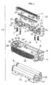
- the reciprocation type electric shaver 100 in accordance with the embodiment is configured that a head unit 101 is coupled with a main body 102 capable of swinging freely.
- An outside blade unit 110 which is comprised of a head cover 111, an outside blade holder 8, a slit blade 112 used for rough shaving and two main blades 113 disposed on both sides of the slit blade 112, is detachably attached to the head unit 101.
- FIG. 1 shows a configuration of the outside blade unit 110.
- Each main blade 113 is comprised of an inside blade holder 10 and an outside blade 9 having a foil shape and attached to the inside blade holder 10.
- the inside blade holder 10 has engaging protrusions 13 protruded from side face thereof to be engaged with engaging recesses 18 formed on an inner side faces of an outside blade holder 8, and guide protrusions 24 protruded from both end faces in a longitudinal direction of the outside blade unit 110 to be engaged with guide grooves 25 on an inner end faces of the outside blade holder 8.
- the slit blade 112 is comprised of a stationary blade 1 having a substantially comb shape and a moving blade 2 which is reciprocally moved with contacting to an inside face of the stationary blade 1.
- the main blade 113 is comprised of the outside blade 9 having a lot of blade holes and an inside blade 11 which is reciprocally moved with contacting to an inside face of the outside blade 9.
- the slit blade 112 and the main blades 113 are respectively held on the outside blade holder 8 capable of floating up and down.
- the slit blade 112 and the main blades 113 are respectively driven in reciprocal motion by a driving force of the motor 14.
- the slit blade 112 is held by upward pressing forces of floating springs 6 and 7.
- a support member 5 is disposed below the stationary blade 1, and slit blade joints 3 and 4 are respectively disposed on both side of the support 5 in the longitudinal direction.
- Each of the support member 5 and the slit blade joints 3 and 4 has heat seal bosses 33 formed on both sides thereof.
- each of the stationary blade 1 and the moving blade 2 has plural pairs of hooks 34 formed on both sides thereof.
- the heat seal bosses 33 of the slit blade joints 3 and 4 are melted so that the stationary blade 1 is fixed to the slit blade joints 3 and 4 under a condition that the hooks 34 of the stationary blade 1 are engaged with the heat seal bosses 33 of the slit blade joints 3 and 4.
- heat seal bosses 33 of the support member 5 are melted so that the moving blade 2 is fixed to the support blade 2 under a condition that the hooks 34 of the moving blade 2 are engaged with the heat seal bosses 33 of the support member 5.
- each of the slit blade joints 3 and 4 has a first spring support boss 50 formed to protrude upward from a bottom face 41 and a second spring support boss 37 is formed to protrude downward from a ceiling face 42.
- a third spring support boss 51 is formed to protrude downward from both end portion of the support member 5 in the longitudinal direction.
- a pair of hooking protrusions 40 is formed at counter-cornered positions on both side faces of the supporting member 5, and hooking holes 15 are formed on both side faces of the moving blade 2 corresponding to the hooking protrusions 40.
- Each floating spring 6 is supported between the first spring support boss 50 of each of the slit blade joints 3 and 4 and the third spring support boss 51 of the support member 5. Thereby, a unified body of the support member 5 and the moving blade 2 is pressed to the stationary blade 1 by the pressure of the floating springs 6 and movably held in the longitudinal direction in an inner space between the stationary blade 1 and the slit blade joints 3 and 4.
- each of the slit blade joints 3 and 4 has a hooking piece 19 protruded downward at an end facing to an inner face of the outside blade holder 8.
- a protrusion 22 is further formed on an outer face of the hooking piece 19 protruded outward.
- FIG. 9 shows a state that the hooking piece 19 is engaged with a hooking groove 16 formed on the inner face of the outside blade holder 8.
- a pair of fourth spring support bosses 31 is formed to protrude upward from a bottom face of the outside blade holder 8 at positions corresponding to the second spring support bosses 37 of the slit blade joints 3 and 4.
- Each of the floating springs 7 is supported between the second spring support boss 37 of each of the slit blade joints 3 and 4 and the fourth spring support boss 31 of the outside blade holder 8.
- a pair of holes 32 is formed on the bottom face of the outside blade holder 8 in the vicinities of the fourth spring support bosses 31, through which shaved chips are fallen. Thereby, it is possible to prevent piling up of the shaved chips, so that the slit blade 112 can be floated smoothly.
- a pair of operation buttons 12 is provided on both sides of the outside blade holder 8 in the longitudinal direction which serves as an element of an attaching and detaching structure and is used to detach the outside blade holder 8 from the outside blade unit 110.
- the outside blade holder 8 further has a pair of elastic frames 23 provided front and rear side thereof and elastically deformed in the longitudinal direction designated by arrow E and in the lateral direction designated by arrow F. The elastic frames 23 are deformed by pushing the operation buttons 12 from both sides in the longitudinal direction, so that the outside blade holder 8 can be detached entirely from the outside blade unit 110.
- a coupling structure 120 for coupling the slit blade 112 on the outside blade holder 8 capable of floating up and down is configured by the hooking piece 19 formed on each of the slit blade joints 3 and 4 and the hooking groove 16 formed on the inner face 8a of the outside blade holder 8.
- a pair of side walls 16a constituting the hooking groove 16 is formed to protrude inwardly from the inner face 8a of the outside blade holder 8.
- a pair of fitting protrusions 17 is further formed to protrude in the lateral direction designated by arrow F for facing each other from inward ends of the side walls 16a.
- both coupling structures 120 provided on both sides of the outside blade holder 8 in the longitudinal direction have the same configuration and arranged symmetrical with respect to the center lines of the slit blade 112 in the lateral directions. Furthermore, each coupling structure 120 is configured symmetrical with respect to the center line of the slit blade 112 in the longitudinal direction.
- the fitting protrusions 17 formed on the outside blade holder 8 and the fitting recess 20 formed on the slit blade joints 3 and 4 serve as a retaining structure 130 for preventing the disengagement of the slit blade 112 from the outside blade holder 8 when the slit blade 112 is floated up and down, especially floated with inclination.
- the fitting recesses 20 are formed to concave on upper half of both sides 19c of the hooking piece 19 of the slit joints 3 and 4 in the lateral direction designated by arrow F in FIG. 9.
- Each fitting recess 20 has a rectangular shape longer in heightwise when it is observed from the lateral direction.
- the fitting protrusions 17 are formed on upper ends of the side walls 16a of the hooking groove 16.
- a dimension of the fitting recess 20 is a little larger than a dimension of the fitting protrusion 17 in heightwise direction of the outside blade unit 110 designated by arrow G, so that the slit blade 112 can be floated up and down with respect to the outside blade holder 8 by a difference between the dimensions of the fitting recess 20 and the fitting protrusion 17.
- the fitting protrusions 17 are fitted to the fitting recesses 20 in the lateral direction shown by arrow F, it is possible to prevent the disengagement of the hooking piece 19 from the hooking groove 16 even when the slit blade 112 is floated with inclination.
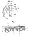
- FIG. 11 a state that the slit blade 112 is floated with inclination is shown in FIG. 11.
- one dotted chain line N designates a reference line when the slit blade 112 is not floated, that is the slit blade 112 is parallel to the upper edge of the outside blade holder 8.
- the disengagement of the slit blade 112 from the outside blade holder 8 in the longitudinal direction designated by arrow E can be prevented by hooking of the hooking pieces 19 of the slit blade joints 3 and 4 with the hooking grooves 16 of the outside blade holder 8. Furthermore, the disengagement of the slit blade 112 from the outside blade holder 8 in the lateral direction designated by arrow F can be prevented by fitting of the fitting protrusions 17 formed on the side walls 16a of the hooking grooves 16 and the fitting recess 20 formed on the hooking pieces 19.
- the fitting protrusions 17 and the fitting recesses 20 can serve as a retaining structure for preventing the disengagement of the slit blade 112 from the outside blade holder 8 upward in the heightwise direction designated by arrow G. Therefore, the slit blade 112 is rarely disengaged from the outside blade holder 8 even when the slit blade 112 is floated with inclination, so that it is possible to increase the displacement of the slit blade in the heightwise direction. Consequently, it is possible to improve the contact feeling to the skin. Furthermore, the hooking dimension of the hooking piece 19 in the longitudinal direction can be shortened, so that the lengths of the slit blade 112 and the outside blade holder 8 in the longitudinal direction can be shortened, too.
- the slit blade 112 and the outside blade holder 8 can be downsized, so that the following characteristic of the blades to concave and convex surface of skin is improved, and the contact feeling to the skin is increased higher. Still furthermore, end portions of the slit blade 112 and the outside blade holder 8 in the longitudinal direction rarely touch the skin, so that the following characteristic of the blades to concave and convex surface of skin is improved much higher, and the contact feeling to the skin is increased much higher.
- side walls 19a and 19b of the fitting recess 20 are formed to protrude in the lateral direction designated by arrow F, in other words, the thickness of the hooking piece 19 in the lateral direction is partially made thicker, so that the mechanical strength of the hooking piece 19 is increased. Consequently, the rigidity of the entire of the slit blade 112 can be ensured, so that it is possible to reduce the impact to the slit blade 112 even when the electric shaver 100 is fallen.
- the slit blade 112 can be floated smoother, and gaps between the slit blade 112 and the main blades 113 can be maintained even. Consequently, it is possible to prevent that the blade cuts into the skin deeper.
- the outside blade holder 8 When the operation buttons 12 of the outside blade holder 8 is inwardly pushed in the longitudinal direction by fingers, the outside blade holder 8 is elastically deformed, so that it is easily detached from the head cover 111. Thereby, the slit blade 112 and the main blades 113 can be washed or replaced, easily. Furthermore, the impact applied to the blades due to falling of the electric shaver can be reduced by the elasticity of the outside blade holder 8. Still furthermore, it is possible to prevent the spill of the shaved chips from both sides of the outside blade holder 8 in the longitudinal direction by the elasticity of the outside blade holder 8.
- the fitting protrusions 17 serve as positioning guide of the fitting pieces 19 of the slit blade joints 3 and 4 disposed at both sides of the slit blade 112 in the longitudinal direction, so that the hooking pieces 19 are evenly inserted into the hooking grooves 16 on the both sides of the outside blade holder 8. Consequently, plastic deformation of the hooking pieces 19 and/or the side walls 16a of the hooking grooves 16 can be prevented.
- the inclination of the slit blade 112 with respect to the outside blade holder 8 when the slit blade 112 is attached to the outside blade holder 8 can be reduced, so that the floating springs 7 can easily and simultaneously attached between the silt blade 112 and the outside blade holder 8. Consequently, the assemble workability of the outside blade unit 110 of the electric shaver can be increased.
- the chamfer serves as a guide to reduce the displacement of the hooking pieces 19 with respect to the hooking grooves 16 when the slit blade 112 is attached to the outside blade holder 8. Consequently, the assemble workability of the outside blade unit 110 of the electric shaver 100 can be increased. Still furthermore, it is possible to prevent that the appearance of the outside blade holder 8 is damaged while the outside blade unit 110 is assembled.
- the outside blade unit 110 having one slit blade 112 and two man blades 113 is described as an example.
- the numbers of the slit blade 112 and the main blade 113 are not limited to the above description. It is possible to constitute the outside blade unit to have, for example, one slit blade and one main blade.
Landscapes
- Life Sciences & Earth Sciences (AREA)
- Forests & Forestry (AREA)
- Engineering & Computer Science (AREA)
- Mechanical Engineering (AREA)
- Dry Shavers And Clippers (AREA)
Applications Claiming Priority (1)
| Application Number | Priority Date | Filing Date | Title |
|---|---|---|---|
| JP2004381386A JP4725103B2 (ja) | 2004-12-28 | 2004-12-28 | 往復式電気かみそり |
Publications (3)
| Publication Number | Publication Date |
|---|---|
| EP1676680A2 true EP1676680A2 (de) | 2006-07-05 |
| EP1676680A3 EP1676680A3 (de) | 2006-08-16 |
| EP1676680B1 EP1676680B1 (de) | 2010-05-12 |
Family
ID=36143716
Family Applications (1)
| Application Number | Title | Priority Date | Filing Date |
|---|---|---|---|
| EP05258090A Expired - Lifetime EP1676680B1 (de) | 2004-12-28 | 2005-12-28 | Elektrischer Vibrationsrasierapparat |
Country Status (7)
| Country | Link |
|---|---|
| US (1) | US7464471B2 (de) |
| EP (1) | EP1676680B1 (de) |
| JP (1) | JP4725103B2 (de) |
| KR (1) | KR100742626B1 (de) |
| CN (2) | CN2866031Y (de) |
| AT (1) | ATE467491T1 (de) |
| DE (1) | DE602005021195D1 (de) |
Cited By (4)
| Publication number | Priority date | Publication date | Assignee | Title |
|---|---|---|---|---|
| EP1886776A1 (de) * | 2006-08-11 | 2008-02-13 | Izumi Products Company | Elektrischer Kolbenrasierapparat |
| EP1886775A1 (de) * | 2006-08-11 | 2008-02-13 | Izumi Products Company | Elektrischer Kolbenrasierapparat |
| EP1886774A1 (de) * | 2006-08-11 | 2008-02-13 | Izumi Products Company | Rastvorrichtung für einen elektrischen Rasierapparat |
| EP2208590A1 (de) * | 2009-01-16 | 2010-07-21 | Panasonic Electric Works Co., Ltd. | Elektrischer Rasierapparat |
Families Citing this family (34)
| Publication number | Priority date | Publication date | Assignee | Title |
|---|---|---|---|---|
| JP4725103B2 (ja) * | 2004-12-28 | 2011-07-13 | パナソニック電工株式会社 | 往復式電気かみそり |
| GB2425277B (en) * | 2005-02-11 | 2009-12-02 | Gillette Co | Electric razor assembly |
| JP4604846B2 (ja) * | 2005-05-31 | 2011-01-05 | パナソニック電工株式会社 | 体毛処理器具 |
| JP4229091B2 (ja) * | 2005-05-31 | 2009-02-25 | パナソニック電工株式会社 | 体毛処理器具 |
| JP4715425B2 (ja) * | 2005-09-27 | 2011-07-06 | パナソニック電工株式会社 | 電気かみそり |
| KR200409341Y1 (ko) * | 2005-12-02 | 2006-02-22 | 오태준 | 헤드무빙 전기면도기 |
| JP4127290B2 (ja) * | 2006-04-25 | 2008-07-30 | 松下電工株式会社 | 電気かみそり用の内刃及び往復式電気かみそり |
| DE102006034050A1 (de) * | 2006-07-20 | 2008-01-24 | Braun Gmbh | Elektrischer Rasierapparat |
| JP4225329B2 (ja) * | 2006-07-21 | 2009-02-18 | パナソニック電工株式会社 | 電気かみそり |
| JP2008093284A (ja) * | 2006-10-13 | 2008-04-24 | Matsushita Electric Works Ltd | 往復動式電気カミソリの外刃およびその製造方法 |
| JP4595967B2 (ja) * | 2007-07-12 | 2010-12-08 | パナソニック電工株式会社 | 往復式電気かみそりの刃 |
| JP4595968B2 (ja) * | 2007-07-12 | 2010-12-08 | パナソニック電工株式会社 | 往復式電気かみそりの内刃 |
| CA2763243C (en) * | 2009-05-28 | 2016-10-25 | Koninklijke Philips Electronics N.V. | Pivoting arrangement |
| US20120151774A1 (en) * | 2009-09-25 | 2012-06-21 | Panasonic Corporation | Electric shaver |
| EP2425938B1 (de) * | 2010-09-03 | 2014-02-26 | Braun GmbH | Rasierkopf mit mehreren Rasiereinheiten |
| JP5603198B2 (ja) * | 2010-10-14 | 2014-10-08 | パナソニック株式会社 | 電気かみそり |
| CN102689318B (zh) * | 2012-06-14 | 2014-11-26 | 浙江海顺电工有限公司 | 一种剃须刀及其往复式“t”字型刀头装置 |
| US20150314461A1 (en) * | 2014-05-02 | 2015-11-05 | Raymond Industrial Ltd. | Hybrid Shaving System |
| US9713877B2 (en) | 2014-11-12 | 2017-07-25 | Medline Industries, Inc. | Clipper head with drag reduction |
| USD779123S1 (en) | 2014-11-12 | 2017-02-14 | Medline Industries, Inc. | Clipper head |
| JP6471984B2 (ja) * | 2016-06-16 | 2019-02-20 | パナソニックIpマネジメント株式会社 | 電気かみそり、当該電気かみそりで用いられる外刃 |
| EP3300856B1 (de) | 2016-09-28 | 2021-06-02 | Braun GmbH | Bartschneider |
| EP3300847B1 (de) * | 2016-09-28 | 2019-10-30 | Braun GmbH | Bartschneider |
| EP3300857A1 (de) | 2016-09-28 | 2018-04-04 | Braun GmbH | Bartschneider |
| CN107650162A (zh) * | 2017-06-15 | 2018-02-02 | 东莞市润佳电器科技有限公司 | 新型多功能剃须刀 |
| USD952946S1 (en) | 2017-09-01 | 2022-05-24 | Church & Dwight Co., Inc. | Hair removal device |
| USD914977S1 (en) | 2019-07-19 | 2021-03-30 | Church & Dwight Co., Inc. | Handle for hair removal apparatus |
| USD925830S1 (en) | 2019-07-19 | 2021-07-20 | Church & Dwight Co., Inc. | Head assembly for hair removal apparatus |
| CN112549090B (zh) * | 2019-09-26 | 2024-03-19 | 麦克赛尔泉株式会社 | 往复式电动剃刀 |
| USD914978S1 (en) | 2019-10-18 | 2021-03-30 | Church & Dwight Co., Inc. | Hair removal apparatus |
| USD936899S1 (en) | 2019-10-18 | 2021-11-23 | Church & Dwight Co., Inc. | Hair removal apparatus |
| USD940958S1 (en) | 2019-11-18 | 2022-01-11 | Church & Dwight Co., Inc. | Articulating blade assembly for hair removal device |
| USD942687S1 (en) | 2019-11-18 | 2022-02-01 | Church & Dwight Co., Inc. | Articulating blade assembly for hair removal device |
| EP4124419B1 (de) * | 2021-07-29 | 2025-07-16 | Braun GmbH | Haarentfernungsvorrichtung |
Citations (3)
| Publication number | Priority date | Publication date | Assignee | Title |
|---|---|---|---|---|
| WO1994023913A1 (de) | 1993-04-13 | 1994-10-27 | Braun Aktiengesellschaft | Scherkopf für einen trockenrasierapparat |
| JPH09253353A (ja) | 1996-03-19 | 1997-09-30 | Izumi Prod Co | 往復式電気かみそり |
| JP2006181289A (ja) | 2004-12-28 | 2006-07-13 | Matsushita Electric Works Ltd | 往復式電気かみそり |
Family Cites Families (12)
| Publication number | Priority date | Publication date | Assignee | Title |
|---|---|---|---|---|
| US237310A (en) * | 1881-02-01 | Foed l | ||
| JP2686017B2 (ja) * | 1992-04-23 | 1997-12-08 | 松下電工株式会社 | 往復式電気かみそり |
| US5398412A (en) * | 1992-04-23 | 1995-03-21 | Matsushita Electric Works, Ltd. | Reciprocatory dry shaver |
| JPH0919571A (ja) * | 1995-07-07 | 1997-01-21 | Matsushita Electric Works Ltd | 往復式電気かみそり |
| US6098288A (en) * | 1996-03-26 | 2000-08-08 | Matsushita Electric Works, Ltd. | Reciprocating-type electric shaver |
| JP3814965B2 (ja) * | 1997-07-28 | 2006-08-30 | 松下電工株式会社 | 往復式電気かみそり |
| JP3747620B2 (ja) * | 1998-03-26 | 2006-02-22 | 松下電工株式会社 | 往復式電気かみそり |
| JP3721783B2 (ja) * | 1998-05-26 | 2005-11-30 | 松下電工株式会社 | 往復式電気かみそり |
| CN100410032C (zh) * | 2001-09-10 | 2008-08-13 | 松下电工株式会社 | 干剃须刀的内刀头的制造方法 |
| JP3979052B2 (ja) | 2001-09-25 | 2007-09-19 | 松下電工株式会社 | 往復式電気かみそり |
| JP4273786B2 (ja) * | 2003-02-25 | 2009-06-03 | パナソニック電工株式会社 | 電気かみそり |
| JP4127290B2 (ja) * | 2006-04-25 | 2008-07-30 | 松下電工株式会社 | 電気かみそり用の内刃及び往復式電気かみそり |
-
2004
- 2004-12-28 JP JP2004381386A patent/JP4725103B2/ja not_active Expired - Fee Related
-
2005
- 2005-12-26 KR KR1020050129591A patent/KR100742626B1/ko not_active Expired - Fee Related
- 2005-12-28 CN CNU2005200373709U patent/CN2866031Y/zh not_active Expired - Lifetime
- 2005-12-28 DE DE602005021195T patent/DE602005021195D1/de not_active Expired - Lifetime
- 2005-12-28 CN CNB2005100488069A patent/CN100410033C/zh not_active Expired - Fee Related
- 2005-12-28 AT AT05258090T patent/ATE467491T1/de not_active IP Right Cessation
- 2005-12-28 US US11/318,561 patent/US7464471B2/en not_active Expired - Lifetime
- 2005-12-28 EP EP05258090A patent/EP1676680B1/de not_active Expired - Lifetime
Patent Citations (3)
| Publication number | Priority date | Publication date | Assignee | Title |
|---|---|---|---|---|
| WO1994023913A1 (de) | 1993-04-13 | 1994-10-27 | Braun Aktiengesellschaft | Scherkopf für einen trockenrasierapparat |
| JPH09253353A (ja) | 1996-03-19 | 1997-09-30 | Izumi Prod Co | 往復式電気かみそり |
| JP2006181289A (ja) | 2004-12-28 | 2006-07-13 | Matsushita Electric Works Ltd | 往復式電気かみそり |
Cited By (7)
| Publication number | Priority date | Publication date | Assignee | Title |
|---|---|---|---|---|
| EP1886776A1 (de) * | 2006-08-11 | 2008-02-13 | Izumi Products Company | Elektrischer Kolbenrasierapparat |
| EP1886775A1 (de) * | 2006-08-11 | 2008-02-13 | Izumi Products Company | Elektrischer Kolbenrasierapparat |
| EP1886774A1 (de) * | 2006-08-11 | 2008-02-13 | Izumi Products Company | Rastvorrichtung für einen elektrischen Rasierapparat |
| US7707726B2 (en) | 2006-08-11 | 2010-05-04 | Izumi Products Company | Reciprocating electric shaver |
| US8136249B2 (en) | 2006-08-11 | 2012-03-20 | Izumi Products Company | Locking device |
| EP2208590A1 (de) * | 2009-01-16 | 2010-07-21 | Panasonic Electric Works Co., Ltd. | Elektrischer Rasierapparat |
| US8479397B2 (en) | 2009-01-16 | 2013-07-09 | Panasonic Corporation | Electric shaver |
Also Published As
| Publication number | Publication date |
|---|---|
| JP4725103B2 (ja) | 2011-07-13 |
| CN2866031Y (zh) | 2007-02-07 |
| ATE467491T1 (de) | 2010-05-15 |
| DE602005021195D1 (de) | 2010-06-24 |
| KR100742626B1 (ko) | 2007-07-25 |
| EP1676680A3 (de) | 2006-08-16 |
| EP1676680B1 (de) | 2010-05-12 |
| US20060137187A1 (en) | 2006-06-29 |
| CN1807034A (zh) | 2006-07-26 |
| US7464471B2 (en) | 2008-12-16 |
| JP2006181289A (ja) | 2006-07-13 |
| KR20060079748A (ko) | 2006-07-06 |
| CN100410033C (zh) | 2008-08-13 |
Similar Documents
| Publication | Publication Date | Title |
|---|---|---|
| EP1676680B1 (de) | Elektrischer Vibrationsrasierapparat | |
| US6073348A (en) | Reciprocating electric shaver | |
| KR100894759B1 (ko) | 전기면도기 | |
| US5189792A (en) | Reciprocatory electric shaver | |
| CN101687327B (zh) | 往复式电动剃刀的内刃 | |
| CN100352625C (zh) | 电动剃须刀 | |
| EP3378611A1 (de) | Rasierer | |
| CN101687326B (zh) | 往复式电动剃刀的刃 | |
| JP4873454B2 (ja) | 電気かみそり | |
| JP3721783B2 (ja) | 往復式電気かみそり | |
| JP4863271B2 (ja) | 電気かみそり | |
| JP4378913B2 (ja) | 往復式電気かみそり | |
| JP2567081Y2 (ja) | 往復式電気かみそり | |
| JP2823319B2 (ja) | 往復式電気かみそり | |
| JP5603198B2 (ja) | 電気かみそり | |
| HK1020178A (en) | Reciprocating electric shaver | |
| HK1020178B (en) | Reciprocating electric shaver | |
| JPH06182062A (ja) | 往復式電気かみそり | |
| HK1139359A (zh) | 往复式电动剃刀的内刃 | |
| HK1138810A (en) | Blade of reciprocating electric shaver | |
| JP2001300158A (ja) | 往復式電気かみそり | |
| JPH0919571A (ja) | 往復式電気かみそり | |
| JPH04348786A (ja) | 往復式電気かみそり |
Legal Events
| Date | Code | Title | Description |
|---|---|---|---|
| PUAI | Public reference made under article 153(3) epc to a published international application that has entered the european phase |
Free format text: ORIGINAL CODE: 0009012 |
|
| AK | Designated contracting states |
Kind code of ref document: A2 Designated state(s): AT BE BG CH CY CZ DE DK EE ES FI FR GB GR HU IE IS IT LI LT LU LV MC NL PL PT RO SE SI SK TR |
|
| AX | Request for extension of the european patent |
Extension state: AL BA HR MK YU |
|
| PUAL | Search report despatched |
Free format text: ORIGINAL CODE: 0009013 |
|
| AK | Designated contracting states |
Kind code of ref document: A3 Designated state(s): AT BE BG CH CY CZ DE DK EE ES FI FR GB GR HU IE IS IT LI LT LU LV MC NL PL PT RO SE SI SK TR |
|
| AX | Request for extension of the european patent |
Extension state: AL BA HR MK YU |
|
| 17P | Request for examination filed |
Effective date: 20061009 |
|
| AKX | Designation fees paid |
Designated state(s): AT BE BG CH CY CZ DE DK EE ES FI FR GB GR HU IE IS IT LI LT LU LV MC NL PL PT RO SE SI SK TR |
|
| 17Q | First examination report despatched |
Effective date: 20071023 |
|
| RAP1 | Party data changed (applicant data changed or rights of an application transferred) |
Owner name: PANASONIC ELECTRIC WORKS CO., LTD. |
|
| GRAP | Despatch of communication of intention to grant a patent |
Free format text: ORIGINAL CODE: EPIDOSNIGR1 |
|
| RIN1 | Information on inventor provided before grant (corrected) |
Inventor name: KOMORI, SHUNSUKE Inventor name: SHIBA, TAKESHI Inventor name: FUKUTANI, MAKOTO |
|
| GRAS | Grant fee paid |
Free format text: ORIGINAL CODE: EPIDOSNIGR3 |
|
| GRAA | (expected) grant |
Free format text: ORIGINAL CODE: 0009210 |
|
| AK | Designated contracting states |
Kind code of ref document: B1 Designated state(s): AT BE BG CH CY CZ DE DK EE ES FI FR GB GR HU IE IS IT LI LT LU LV MC NL PL PT RO SE SI SK TR |
|
| REG | Reference to a national code |
Ref country code: GB Ref legal event code: FG4D |
|
| REG | Reference to a national code |
Ref country code: CH Ref legal event code: EP |
|
| REG | Reference to a national code |
Ref country code: IE Ref legal event code: FG4D |
|
| REF | Corresponds to: |
Ref document number: 602005021195 Country of ref document: DE Date of ref document: 20100624 Kind code of ref document: P |
|
| REG | Reference to a national code |
Ref country code: NL Ref legal event code: VDEP Effective date: 20100512 |
|
| LTIE | Lt: invalidation of european patent or patent extension |
Effective date: 20100512 |
|
| PG25 | Lapsed in a contracting state [announced via postgrant information from national office to epo] |
Ref country code: NL Free format text: LAPSE BECAUSE OF FAILURE TO SUBMIT A TRANSLATION OF THE DESCRIPTION OR TO PAY THE FEE WITHIN THE PRESCRIBED TIME-LIMIT Effective date: 20100512 Ref country code: SE Free format text: LAPSE BECAUSE OF FAILURE TO SUBMIT A TRANSLATION OF THE DESCRIPTION OR TO PAY THE FEE WITHIN THE PRESCRIBED TIME-LIMIT Effective date: 20100512 Ref country code: LT Free format text: LAPSE BECAUSE OF FAILURE TO SUBMIT A TRANSLATION OF THE DESCRIPTION OR TO PAY THE FEE WITHIN THE PRESCRIBED TIME-LIMIT Effective date: 20100512 Ref country code: ES Free format text: LAPSE BECAUSE OF FAILURE TO SUBMIT A TRANSLATION OF THE DESCRIPTION OR TO PAY THE FEE WITHIN THE PRESCRIBED TIME-LIMIT Effective date: 20100823 |
|
| PG25 | Lapsed in a contracting state [announced via postgrant information from national office to epo] |
Ref country code: FI Free format text: LAPSE BECAUSE OF FAILURE TO SUBMIT A TRANSLATION OF THE DESCRIPTION OR TO PAY THE FEE WITHIN THE PRESCRIBED TIME-LIMIT Effective date: 20100512 Ref country code: LV Free format text: LAPSE BECAUSE OF FAILURE TO SUBMIT A TRANSLATION OF THE DESCRIPTION OR TO PAY THE FEE WITHIN THE PRESCRIBED TIME-LIMIT Effective date: 20100512 Ref country code: SI Free format text: LAPSE BECAUSE OF FAILURE TO SUBMIT A TRANSLATION OF THE DESCRIPTION OR TO PAY THE FEE WITHIN THE PRESCRIBED TIME-LIMIT Effective date: 20100512 Ref country code: AT Free format text: LAPSE BECAUSE OF FAILURE TO SUBMIT A TRANSLATION OF THE DESCRIPTION OR TO PAY THE FEE WITHIN THE PRESCRIBED TIME-LIMIT Effective date: 20100512 Ref country code: IS Free format text: LAPSE BECAUSE OF FAILURE TO SUBMIT A TRANSLATION OF THE DESCRIPTION OR TO PAY THE FEE WITHIN THE PRESCRIBED TIME-LIMIT Effective date: 20100912 |
|
| PG25 | Lapsed in a contracting state [announced via postgrant information from national office to epo] |
Ref country code: PL Free format text: LAPSE BECAUSE OF FAILURE TO SUBMIT A TRANSLATION OF THE DESCRIPTION OR TO PAY THE FEE WITHIN THE PRESCRIBED TIME-LIMIT Effective date: 20100512 Ref country code: GR Free format text: LAPSE BECAUSE OF FAILURE TO SUBMIT A TRANSLATION OF THE DESCRIPTION OR TO PAY THE FEE WITHIN THE PRESCRIBED TIME-LIMIT Effective date: 20100813 Ref country code: CY Free format text: LAPSE BECAUSE OF FAILURE TO SUBMIT A TRANSLATION OF THE DESCRIPTION OR TO PAY THE FEE WITHIN THE PRESCRIBED TIME-LIMIT Effective date: 20100512 |
|
| PG25 | Lapsed in a contracting state [announced via postgrant information from national office to epo] |
Ref country code: DK Free format text: LAPSE BECAUSE OF FAILURE TO SUBMIT A TRANSLATION OF THE DESCRIPTION OR TO PAY THE FEE WITHIN THE PRESCRIBED TIME-LIMIT Effective date: 20100512 Ref country code: EE Free format text: LAPSE BECAUSE OF FAILURE TO SUBMIT A TRANSLATION OF THE DESCRIPTION OR TO PAY THE FEE WITHIN THE PRESCRIBED TIME-LIMIT Effective date: 20100512 Ref country code: PT Free format text: LAPSE BECAUSE OF FAILURE TO SUBMIT A TRANSLATION OF THE DESCRIPTION OR TO PAY THE FEE WITHIN THE PRESCRIBED TIME-LIMIT Effective date: 20100913 |
|
| PG25 | Lapsed in a contracting state [announced via postgrant information from national office to epo] |
Ref country code: BE Free format text: LAPSE BECAUSE OF FAILURE TO SUBMIT A TRANSLATION OF THE DESCRIPTION OR TO PAY THE FEE WITHIN THE PRESCRIBED TIME-LIMIT Effective date: 20100512 Ref country code: CZ Free format text: LAPSE BECAUSE OF FAILURE TO SUBMIT A TRANSLATION OF THE DESCRIPTION OR TO PAY THE FEE WITHIN THE PRESCRIBED TIME-LIMIT Effective date: 20100512 Ref country code: RO Free format text: LAPSE BECAUSE OF FAILURE TO SUBMIT A TRANSLATION OF THE DESCRIPTION OR TO PAY THE FEE WITHIN THE PRESCRIBED TIME-LIMIT Effective date: 20100512 Ref country code: SK Free format text: LAPSE BECAUSE OF FAILURE TO SUBMIT A TRANSLATION OF THE DESCRIPTION OR TO PAY THE FEE WITHIN THE PRESCRIBED TIME-LIMIT Effective date: 20100512 |
|
| PLBE | No opposition filed within time limit |
Free format text: ORIGINAL CODE: 0009261 |
|
| STAA | Information on the status of an ep patent application or granted ep patent |
Free format text: STATUS: NO OPPOSITION FILED WITHIN TIME LIMIT |
|
| 26N | No opposition filed |
Effective date: 20110215 |
|
| REG | Reference to a national code |
Ref country code: DE Ref legal event code: R097 Ref document number: 602005021195 Country of ref document: DE Effective date: 20110214 |
|
| PG25 | Lapsed in a contracting state [announced via postgrant information from national office to epo] |
Ref country code: MC Free format text: LAPSE BECAUSE OF NON-PAYMENT OF DUE FEES Effective date: 20101231 |
|
| REG | Reference to a national code |
Ref country code: CH Ref legal event code: PL |
|
| REG | Reference to a national code |
Ref country code: FR Ref legal event code: ST Effective date: 20110831 |
|
| PG25 | Lapsed in a contracting state [announced via postgrant information from national office to epo] |
Ref country code: FR Free format text: LAPSE BECAUSE OF NON-PAYMENT OF DUE FEES Effective date: 20110103 Ref country code: IE Free format text: LAPSE BECAUSE OF NON-PAYMENT OF DUE FEES Effective date: 20101228 Ref country code: LI Free format text: LAPSE BECAUSE OF NON-PAYMENT OF DUE FEES Effective date: 20101231 Ref country code: CH Free format text: LAPSE BECAUSE OF NON-PAYMENT OF DUE FEES Effective date: 20101231 |
|
| PG25 | Lapsed in a contracting state [announced via postgrant information from national office to epo] |
Ref country code: BG Free format text: LAPSE BECAUSE OF FAILURE TO SUBMIT A TRANSLATION OF THE DESCRIPTION OR TO PAY THE FEE WITHIN THE PRESCRIBED TIME-LIMIT Effective date: 20100512 Ref country code: LU Free format text: LAPSE BECAUSE OF NON-PAYMENT OF DUE FEES Effective date: 20101228 Ref country code: HU Free format text: LAPSE BECAUSE OF FAILURE TO SUBMIT A TRANSLATION OF THE DESCRIPTION OR TO PAY THE FEE WITHIN THE PRESCRIBED TIME-LIMIT Effective date: 20101113 |
|
| PG25 | Lapsed in a contracting state [announced via postgrant information from national office to epo] |
Ref country code: TR Free format text: LAPSE BECAUSE OF FAILURE TO SUBMIT A TRANSLATION OF THE DESCRIPTION OR TO PAY THE FEE WITHIN THE PRESCRIBED TIME-LIMIT Effective date: 20100512 |
|
| PGFP | Annual fee paid to national office [announced via postgrant information from national office to epo] |
Ref country code: GB Payment date: 20121227 Year of fee payment: 8 Ref country code: IT Payment date: 20121218 Year of fee payment: 8 |
|
| PG25 | Lapsed in a contracting state [announced via postgrant information from national office to epo] |
Ref country code: BG Free format text: LAPSE BECAUSE OF FAILURE TO SUBMIT A TRANSLATION OF THE DESCRIPTION OR TO PAY THE FEE WITHIN THE PRESCRIBED TIME-LIMIT Effective date: 20100812 |
|
| GBPC | Gb: european patent ceased through non-payment of renewal fee |
Effective date: 20131228 |
|
| PG25 | Lapsed in a contracting state [announced via postgrant information from national office to epo] |
Ref country code: GB Free format text: LAPSE BECAUSE OF NON-PAYMENT OF DUE FEES Effective date: 20131228 |
|
| PG25 | Lapsed in a contracting state [announced via postgrant information from national office to epo] |
Ref country code: IT Free format text: LAPSE BECAUSE OF NON-PAYMENT OF DUE FEES Effective date: 20131231 |
|
| PG25 | Lapsed in a contracting state [announced via postgrant information from national office to epo] |
Ref country code: IT Free format text: LAPSE BECAUSE OF NON-PAYMENT OF DUE FEES Effective date: 20131228 |
|
| PGFP | Annual fee paid to national office [announced via postgrant information from national office to epo] |
Ref country code: DE Payment date: 20220308 Year of fee payment: 18 |
|
| REG | Reference to a national code |
Ref country code: DE Ref legal event code: R119 Ref document number: 602005021195 Country of ref document: DE |
|
| PG25 | Lapsed in a contracting state [announced via postgrant information from national office to epo] |
Ref country code: DE Free format text: LAPSE BECAUSE OF NON-PAYMENT OF DUE FEES Effective date: 20240702 |
|
| PG25 | Lapsed in a contracting state [announced via postgrant information from national office to epo] |
Ref country code: DE Free format text: LAPSE BECAUSE OF NON-PAYMENT OF DUE FEES Effective date: 20240702 |