EP1676806A1 - Detecteur de defauts de cables metalliques pour ascenseur - Google Patents
Detecteur de defauts de cables metalliques pour ascenseur Download PDFInfo
- Publication number
- EP1676806A1 EP1676806A1 EP04818978A EP04818978A EP1676806A1 EP 1676806 A1 EP1676806 A1 EP 1676806A1 EP 04818978 A EP04818978 A EP 04818978A EP 04818978 A EP04818978 A EP 04818978A EP 1676806 A1 EP1676806 A1 EP 1676806A1
- Authority
- EP
- European Patent Office
- Prior art keywords
- wire rope
- flaw
- detection apparatus
- elevator
- signals
- Prior art date
- Legal status (The legal status is an assumption and is not a legal conclusion. Google has not performed a legal analysis and makes no representation as to the accuracy of the status listed.)
- Withdrawn
Links
Images
Classifications
-
- B—PERFORMING OPERATIONS; TRANSPORTING
- B66—HOISTING; LIFTING; HAULING
- B66B—ELEVATORS; ESCALATORS OR MOVING WALKWAYS
- B66B5/00—Applications of checking, fault-correcting, or safety devices in elevators
- B66B5/02—Applications of checking, fault-correcting, or safety devices in elevators responsive to abnormal operating conditions
- B66B5/12—Applications of checking, fault-correcting, or safety devices in elevators responsive to abnormal operating conditions in case of rope or cable slack
- B66B5/125—Applications of checking, fault-correcting, or safety devices in elevators responsive to abnormal operating conditions in case of rope or cable slack electrical
-
- B—PERFORMING OPERATIONS; TRANSPORTING
- B66—HOISTING; LIFTING; HAULING
- B66B—ELEVATORS; ESCALATORS OR MOVING WALKWAYS
- B66B7/00—Other common features of elevators
- B66B7/12—Checking, lubricating, or cleaning means for ropes, cables or guides
- B66B7/1207—Checking means
- B66B7/1215—Checking means specially adapted for ropes or cables
- B66B7/123—Checking means specially adapted for ropes or cables by analysing magnetic variables
-
- G—PHYSICS
- G01—MEASURING; TESTING
- G01N—INVESTIGATING OR ANALYSING MATERIALS BY DETERMINING THEIR CHEMICAL OR PHYSICAL PROPERTIES
- G01N27/00—Investigating or analysing materials by the use of electric, electrochemical, or magnetic means
- G01N27/72—Investigating or analysing materials by the use of electric, electrochemical, or magnetic means by investigating magnetic variables
- G01N27/82—Investigating or analysing materials by the use of electric, electrochemical, or magnetic means by investigating magnetic variables for investigating the presence of flaws
- G01N27/83—Investigating or analysing materials by the use of electric, electrochemical, or magnetic means by investigating magnetic variables for investigating the presence of flaws by investigating stray magnetic fields
Definitions
- the present invention relates to a flaw detection apparatus for a wire rope of an elevator, which is used for the maintenance of a wire rope suspending an elevator car of an elevator.
- a wire rope supporting an elevator car of an elevator must be maintained in accordance with regulations and repaired as needed.
- breaking and abrasion of wires is checked for by visually observing the wires to determine a remaining strength of the wire rope.
- visual observation is not easy because of the thin wires.
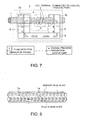
- a magnetic flaw detection apparatus shown in Fig. 7 has conventionally been used for more rapidly detecting a flaw in wires, such as breaking, abrasion, kinks, and so on.
- the reference numbers 1 and 2 show a rope to be measured and a flaw detector (hereinafter referred to as a "probe") of the magnetic flaw detection apparatus, respectively.
- the probe 2 includes a magnetic part 3 for exciting the rope 1 to be measured, and a sensor part 4 for detecting a flux change observed on a surface of the rope 1.
- the magnetic part 3 has a magnet 5 formed of a permanent magnet, a yoke 6 of a rectangular cross-section, and two magnetic poles 7a and 7b each having a U-shaped groove portion.
- a magnetic field is generated in the yoke 6 in a direction shown in Fig. 7, and a magnetic channel is formed inside the measured rope 1 through the magnetic poles 7a and 7b.
- a leakage flux changes the magnetic field in the air at the flaw portion 1a (Fig. 8 is a conceptual view thereof).
- an electromotive force (signal) is generated in the sensor part 4, and then the signal is output to a process/display part 8.
- a maintenance operator can specify the most deteriorated portion in the rope, based on a displayed signal waveform, and determine a strength of the deteriorated portion.
- Such a flaw detection apparatus can facilitate a flaw detection operation, which results in a significant reduction of a time required for the maintenance operation of the rope.
- the sensor part 4 is made of a coil in the example shown in Fig. 7, galvanomagnetic-effect devices (Hall-effect devices) may be alternatively used therefor (not shown).
- the coil When the coil is used, a relative velocity is needed between the measured rope 1 and the probe 2, and a variation of the velocity has an impact on a flaw-detection sensibility.
- the Hall-effect devices serving as detecting elements when used, an output in proportion to a flux density can be obtained, and a flaw-detection sensibility independent from a relative velocity can be provided.
- a wire rope of a diameter smaller than that of a conventional wire rope is used in an elevator, which allows a size reduction of a driving sheave as well as a size reduction of an electric motor by reducing a torque required for a hoist. Therefore, space and energy necessary for the whole structure can be effectively saved.
- the wire rope of a smaller diameter means a wire rope having a nominal diameter of 4 mm to 8 mm.
- the wire rope of such size is formed of wires each having a diameter of about 0.3 mm to 0.7 mm.
- breaking of the wire can be observed with the naked eye.
- the wire rope of a smaller diameter entails an increased number of wires each having a thinner diameter, and a narrower distance between the wire ropes than the conventional one. As a result, a longer time is required for a maintenance operation, especially for a flaw detection operation and a strength determination operation.
- the leakage flux at a flaw portion is generally reduced because of the thinner wires, which leads to a deterioration of a flaw detection sensibility of the leakage flux.
- the ferromagnetic body when there is a ferromagnetic body such as another rope near the measured rope, the ferromagnetic body is magnetized, so that the magnetized ferromagnetic body influences the magnetic sensors censoring the measured rope to generate noise signals other than those showing a flaw.
- these inconveniences may largely be dependent on positions and sizes of the rope and the magnetic sensors, such disadvantages are inconsistent with the desired aspects of the elevator in terms of an achievement of space-saving elevator equipments and an improvement of a flaw detection performance. Accordingly, no concrete idea has been proposed heretofore, with respect to a magnetic flaw detection apparatus which can be suitably used in an elevator having a wire rope of a smaller diameter so as to save space.
- An object of the present invention is to provide a flaw detection apparatus for a wire rope of an elevator, that can provide an enhanced maintenance workability when used in a space- and energy-saving elevator having a wire rope of a smaller diameter.
- the present invention is flaw detection apparatus for a wire rope of an elevator for detecting a flaw portion of a wire rope of an elevator having a nominal diameter of 4mm to 8mm, comprising: a plurality of flaw detectors disposed near the wire rope; wherein each of the flaw detectors has a first and a second magnetic poles of different polarity, and a magnetic sensor of a U-shape disposed between the first and second magnetic poles, each of the U-shaped magnetic sensors has a bottom radius in the range of 2mm to 5mm, a difference between the bottom radius of the magnetic sensor and a half of the nominal diameter of the wire rope being equal to or less than 1.5mm, and a distance between sidewalls of the magnetic sensors of the adjacent flaw detectors in a plan view is equal to or more than 2 mm.
- the adjacent flaw detectors are staggered relative to a longitudinal direction of the wire rope.
- the flaw detection apparatus further comprises a filter for filtering to eliminate noises other than signals showing a flaw of the wire rope from signals that are output from the magnetic sensors of the plurality of flaw detectors, wherein after filtering the noises, all of the rest signals are summed up.
- the flaw detection apparatus further comprises means for eliminating signals under a threshold value from signals that are output from the magnetic sensors of the plurality of flaw detectors, wherein after deleting the signals under the threshold value, all the rest signals are summed up.
- the flaw detection apparatus for a wire rope of an elevator according to the present invention, further comprises securing members for holding and securing the respective flaw detectors on predetermined positions of an elevator shaft or a machineroom.
- the securing members for holding the flaw detectors are disposed near a hoist.
- the securing members hold the flaw detectors at positions where a side surface of the wire rope which is in contact with a groove of a driving sheave of the hoist and bottom surfaces of the magnetic sensors of the flaw detectors are opposed to each other.
- the flaw detection apparatus for a wire rope of an elevator according to the present invention, further comprises securing members for holding and securing the flaw detectors on an elevator car.
- the flaw detection apparatus comprises means for converting analogue signals, that are output from the magnetic sensors of the plurality of flaw detectors, to digital signals and storing the digital signals.
- the flaw detection apparatus further comprises a device for displaying a sum of signals that are output from the magnetic sensors of the plurality of flaw detectors.
- each of the U-shaped magnetic sensors covers at least a semi-circumference or more of the wire rope.
- a flaw of the wire rope in an elevator having a wire rope of a small diameter having a nominal diameter of 4 mm to 8 mm, a flaw of the wire rope can be detected in a highly reliable manner with a minimum space.
- a time required for detecting a flaw can be drastically reduced in an elevator having an increased number of wire ropes. Accordingly, a time period when the elevator is stopped for a maintenance can be shortened, which in turn elongates a time period when the elevator is in service.
- the flaw detection apparatus according to the present invention makes it possible for an operator to gather signals outside an elevator shaft whereby an improved safety is provided.
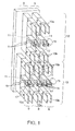
- FIGS. 1 to 6 are views showing an embodiment of the flaw detection apparatus for a wire rope of an elevator according to the present invention.
- the flaw detection apparatus for a wire rope of an elevator can be applied to an elevator using a wire rope of a smaller diameter so as to save space and energy.
- a nominal diameter of the rope is in a range of 4 mm to 8 mm.
- the flaw detection apparatus for a wire rope of an elevator includes a plurality of flaw detectors (unit probes) 9.
- Each of the flaw detectors (unit probes) 9 has a first and a second magnetic poles 10a and 10b of different polarity, and a magnetic sensor 11 of a U-shape disposed between the first magnetic pole 10a and the second magnetic pole 10b.
- the first magnetic pole 10a is a north pole
- the second magnetic pole 10b is a south pole.
- a wire rope 1 is measured when the wire rope 1 is fitted in the first and second magnetic poles 10a and 10 and the magnetic sensor 11 of each of the unit probes 9.
- the measured wire rope 1 is in a tensioned condition.
- a space-saving rope layout can be realized in an elevator.
- the U-shaped magnetic sensor 11 covers at least a semi-circumference or more of the wire rope 1.
- the two unit probes 9 are arranged in parallel in an upper portion 12, while the three unit probes 9 are arranged in parallel in a lower portion 13. That is, the five unit probes 9 are staggered relative to a longitudinal direction of the wire rope 1, so that a flaw detection can be simultaneously carried out for the five wire ropes 1.
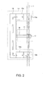
- Each of the unit probes 9 has a magnetic part 14 (see Fig. 2) for exciting the wire rope 1, and the magnetic sensor 11 for detecting a leakage flux (a leakage magnetic flux).
- Fig. 2 shows a side view of the unit probe 9.
- the reference numbers 15a and 15b indicate permanent magnets each having a polarity in a direction shown in Fig. 2.
- the magnetic poles 10a and 10b are formed of a ferromagnetic material, and are adjacent to the permanent magnets 15a and 15b.
- Each of the magnetic poles 10a and 10b has a U-shaped groove in which the measured wire rope 1 is fitted.
- the reference number 16 indicates a yoke formed of a ferromagnetic material for forming a magnetic channel.
- the magnetic sensor 11 has a coil 17, and a base part 18 formed of a nonmagnetic material for holding the coil 17 near a side surface of the measured rope 1.
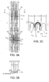
- the reference number 19 in Fig. 3(a) indicates a magnetic shielding plate disposed on the magnetic sensor 11 for shielding noises generated by a leakage flux (a leakage magnetic flux) of the wire rope 1 (the magnetic shielding plate 19 is omitted in Fig. 1 for simplicity).
- Figs. 3(a) to 3(c) show the magnetic sensor 11 whose position and dimension have a great impact on a flaw detection for the plurality of wire ropes 1.
- Fig. 3(a) shows the magnetic sensor 11
- Fig. 3(b) is a cross-sectional view taken along the X-X line shown in Fig. 3(a)
- Fig. 3(c) is an enlargement view of the "A" portion shown in Fig. 3(b).
- the inventors of the present invention tested a flaw detection for the wire ropes 1 of an elevator each having a nominal diameter of 4 mm to 8mm.
- the inventors found that a desired flaw detection sensibility could be obtained with a bottom radius r 1 of the U-shaped magnetic sensor 11 being in a range of 2 mm to 5 mm, a difference between the bottom radius r 1 of the U-shaped magnetic sensor 11 and a half of the nominal diameter (r 0 ) of each wire rope 1 being equal to or less than 1.5 mm, and the radius r 1 of magnetic sensor 11 being greater than the radius ro of the wire rope 1.
- a sliding member 20 formed of a nonmagnetic material is interposed between the magnetic sensor 11 and the measured wire rope 1 for practical use.
- a distance ⁇ 0 between sidewalls of the adjacent magnetic sensors 11 in plan view is set equal to or more than 2 mm including the sliding member 20, and the unit probes 9 are longitudinally staggered.
- the magnetic poles 10a and 10b of each of the unit probes 9 are positioned as shown in Fig. 1. Consequently, noises caused by the leakage flux (leakage magnetic flux) between the adjacent wire ropes 1 can be reduced to a negligible degree for a flaw detection.
- the flaw detection apparatus for a wire rope of an elevator which has the small-sized unit probes 9 capable of detecting a flaw in a highly reliable manner, is adapted to the five wire ropes 1.
- the above features and effects have no relation to the number of ropes.
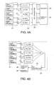
- Fig. 4(a) shows one of the features of a signal process including a signal display of the flaw detection apparatus of the present invention.
- the reference number 21 depicts a probe part including the plurality of unit probes 9 according to the present invention.
- Signals generated in the magnetic sensor 11 of each of the unit probes 9 are transmitted to a signal process part 22 through terminals T1 to T5 of the magnetic sensor 11.
- the signals are amplified in the signal process part 22 (an amplifier is not shown)
- the signals are subjected to a signal process such as filtering if necessary.
- the signals are digitalized by an A/D converter 23.
- the digitalized signals can be easily stored in a memory 24.
- the digitalization of the signals can reduce a deterioration in transmission and memorization of the signals which are carried out downstream the signal process part 22, and can allow a use of a prevailing apparatus such as a personal computer as signal-display means.
- the signals from the unit probes 9 are all transmitted to one display part 25, e.g., a personal computer, and are then simultaneously displayed on a screen. Since all of the wire ropes 1 used in an elevator are fitted in the respective unit probes 9, a flaw detection for all of the ropes can be carried out by only one scanning. Further, since the signals are displayed on a screen all together, a time required for a flaw detection can be largely shortened.
- the reason why the signals can be summed up is as follows: This is because the wire rope 1 of an elevator is apt to be particularly damaged at portions where the wire rope 1 passes round a hoist when an elevator car stops at certain floors. By displaying a sum of the signals, the signals to be observed are noticeable whereby a flaw portion can be easily grasped. It may be considered that noises included in the signals are also summed up, which makes unclear the signals showing a flaw. Thus, in order to avoid the unclear signals, a process shown in Fig. 4(b) such as filtering or eliminating signals of negligible low levels can be carried out before summing up the signals.
- Figs. 4(a) and 4(b) show the memory 24 for storing signals which is integral with the display part 25 for displaying signals
- the memory 24 can be integrally formed with the signal process part 22, and disposed directly downstream the A/D converter 23.
- a detachable nonvolatile memory may be used as the memory 24 disposed directly downstream the A/D converter 23. In this case, after signals are gathered, the memory 24 can be detached from the signal process part 22, and then connected to the display part 25 which is thus separated from the signal process part 22. As a result, a part required for a flaw detection operation can be made compact.
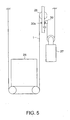
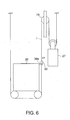
- Figs. 5 and 6 show an example of a machineroom-less elevator using a wire rope of a small diameter.
- the reference number 26 depicts an elevator car
- 27 depicts a counterweight
- 28 depicts a hoist secured in an elevator shaft, e.g., a top thereof
- 30 depicts at least a probe part of the flaw detection apparatus.
- the probe part 30 having the plurality of unit probes 9 is positioned and secured on the measured rope 1 by securing means 30a such that a bottom of the U-shaped magnetic sensor 11 is tightly in contact with the measured rope 1 in a direction of the arrow shown in Fig. 5.
- the probe part 30 is secured near the hoist 28 by the securing means 30a such that a side surface of the measured rope 1 which is in contact with a bottom surface of a groove formed in a driving sheave of the hoist 28 is brought into contact with the bottom of the U-shaped magnetic sensor 11.
- the reason for setting the above direction and position of the probe part 30 relative to the measured rope 1 is as follows: In general, the wire rope 1 is most severely damaged by the driving sheave of the hoist 28. By setting the direction and position of the probe part 30 as mentioned above, it is possible to securely detect a flaw portion of the wire rope 1 passing round the hoist 28.
- the measured wire rope 1 is scanned, and signals are gathered, after the elevator is activated for an inspection operation, for example. Since the flaw detection apparatus for a wire rope of an elevator according to the present invention can be held in the elevator shaft in the manner shown in the drawings, an operator can detect a flaw portion outside the elevator shaft, which contributes, in particular, an improvement of the safety of a machineroom-less elevator.
- the probe part 30 may be secured on the elevator car 26 by the securing means 30a.
- a power can be supplied from the elevator car 26 to the probe part 30.
- an operator can secure the probe part 30 on the elevator car 26 located at any position, a labor required for installing the apparatus can be saved.
Landscapes
- Chemical & Material Sciences (AREA)
- Chemical Kinetics & Catalysis (AREA)
- Electrochemistry (AREA)
- Physics & Mathematics (AREA)
- Health & Medical Sciences (AREA)
- Life Sciences & Earth Sciences (AREA)
- Analytical Chemistry (AREA)
- Biochemistry (AREA)
- General Health & Medical Sciences (AREA)
- General Physics & Mathematics (AREA)
- Immunology (AREA)
- Pathology (AREA)
- Investigating Or Analyzing Materials By The Use Of Magnetic Means (AREA)
- Lift-Guide Devices, And Elevator Ropes And Cables (AREA)
- Maintenance And Inspection Apparatuses For Elevators (AREA)
Applications Claiming Priority (2)
| Application Number | Priority Date | Filing Date | Title |
|---|---|---|---|
| JP2003392788A JP2005154042A (ja) | 2003-11-21 | 2003-11-21 | エレベータ用ワイヤロープ探傷装置 |
| PCT/JP2004/017256 WO2005049471A1 (fr) | 2003-11-21 | 2004-11-19 | Detecteur de defauts de cables metalliques pour ascenseur |
Publications (2)
| Publication Number | Publication Date |
|---|---|
| EP1676806A1 true EP1676806A1 (fr) | 2006-07-05 |
| EP1676806A4 EP1676806A4 (fr) | 2008-02-27 |
Family
ID=34616466
Family Applications (1)
| Application Number | Title | Priority Date | Filing Date |
|---|---|---|---|
| EP04818978A Withdrawn EP1676806A4 (fr) | 2003-11-21 | 2004-11-19 | Detecteur de defauts de cables metalliques pour ascenseur |
Country Status (6)
| Country | Link |
|---|---|
| US (1) | US20070090834A1 (fr) |
| EP (1) | EP1676806A4 (fr) |
| JP (1) | JP2005154042A (fr) |
| CN (1) | CN1882493A (fr) |
| TW (1) | TWI261570B (fr) |
| WO (1) | WO2005049471A1 (fr) |
Cited By (3)
| Publication number | Priority date | Publication date | Assignee | Title |
|---|---|---|---|---|
| WO2009107033A1 (fr) * | 2008-02-28 | 2009-09-03 | Amc Instruments S.R.L. | Dispositif de surveillance de systèmes multicâbles |
| US20100019762A1 (en) * | 2007-01-31 | 2010-01-28 | Mitsubishi Electric Corporation | Wire rope flaw detector |
| US8476898B2 (en) | 2007-11-13 | 2013-07-02 | Mitsubishi Electric Corporation | Rope tester detection plate |
Families Citing this family (40)
| Publication number | Priority date | Publication date | Assignee | Title |
|---|---|---|---|---|
| DE112007003297B4 (de) * | 2007-01-31 | 2015-05-21 | Mitsubishi Electric Corp. | Drahtseildefektdetektor |
| JP4415041B2 (ja) * | 2007-10-10 | 2010-02-17 | 三菱電機ビルテクノサービス株式会社 | ロープ点検方法 |
| JP5023112B2 (ja) * | 2009-07-31 | 2012-09-12 | 株式会社日立製作所 | エレベーター |
| JP5574809B2 (ja) * | 2010-05-07 | 2014-08-20 | 三菱電機株式会社 | ワイヤロープ探傷器およびワイヤロープ探傷器を用いた検出方法 |
| US9136749B1 (en) * | 2012-09-28 | 2015-09-15 | John M. Callier | Elevator electrical power system |
| JP6193077B2 (ja) * | 2012-10-30 | 2017-09-06 | 東京製綱株式会社 | ワイヤロープの検査装置 |
| CN103896122A (zh) * | 2013-06-27 | 2014-07-02 | 洛阳威尔若普检测技术有限公司 | 基于电磁感应的电梯钢丝绳断绳监测装置 |
| DE102013017110A1 (de) * | 2013-08-28 | 2015-03-05 | Liebherr-Components Biberach Gmbh | Vorrichtung zur Erkennung der Ablegereife eines hochfesten Faserseils beim Einsatz an Hebezeugen |
| DE102013111013A1 (de) * | 2013-10-04 | 2015-04-09 | Pfeifer Drako Drahtseilwerk Gmbh & Co. Kg | Einrichtung zum zerstörungsfreien Prüfen von Stahldrahtseilen |
| FI125313B (en) * | 2013-11-12 | 2015-08-31 | Konecranes Oyj | Apparatus and arrangement for monitoring the condition of an object having an elongate iron longitudinal axis |
| JP6226131B2 (ja) * | 2014-02-21 | 2017-11-08 | 住友電工スチールワイヤー株式会社 | Pc鋼材の張力測定装置 |
| US20150239708A1 (en) * | 2014-02-25 | 2015-08-27 | Thyssenkrupp Elevator Ag | System and Method for Monitoring a Load Bearing Member |
| CN104229583A (zh) * | 2014-09-19 | 2014-12-24 | 洛阳泰斯特探伤技术有限公司 | 一种电梯曳引钢丝绳系在线同步感应探伤装置 |
| CN106324080A (zh) * | 2015-06-17 | 2017-01-11 | 江苏省特种设备安全监督检验研究院 | 可移动多回路港口集装箱起重机钢丝绳在线检测装置 |
| WO2017022764A1 (fr) * | 2015-08-06 | 2017-02-09 | 三菱電機株式会社 | Détecteur de défaut de câble métallique |
| KR102008172B1 (ko) * | 2015-08-19 | 2019-08-07 | 미쓰비시덴키 가부시키가이샤 | 와이어 로프 손상 검출 장치 및 조정 지그 |
| CN105293242B (zh) * | 2015-11-25 | 2018-07-17 | 佛山住友富士电梯有限公司 | 一种电梯曳引绳检测装置 |
| US10724992B2 (en) | 2016-03-24 | 2020-07-28 | Mitsubishi Electric Corporation | Wire rope flaw detector and adjustment method therefor |
| CN105675713B (zh) * | 2016-04-06 | 2018-08-07 | 山西慧达澳星科技有限公司 | 一种电梯曳引钢带无损检测装置及方法 |
| WO2017198612A1 (fr) * | 2016-05-17 | 2017-11-23 | Inventio Ag | Procédé et dispositif pour détecter des détériorations dans un moyen de suspension pour une installation d'ascenseur |
| WO2018109824A1 (fr) * | 2016-12-13 | 2018-06-21 | 東京製綱株式会社 | Procédé de détection de dommages d'un câble métallique, et dispositif de traitement de signaux et dispositif de détection de dommages servant à la détection de dommages d'un câble métallique |
| JP2018100167A (ja) * | 2016-12-20 | 2018-06-28 | 東芝エレベータ株式会社 | 異常検出器及び異常検出方法 |
| JP6844431B2 (ja) * | 2017-06-12 | 2021-03-17 | 三菱電機ビルテクノサービス株式会社 | エレベーターのロープ検査装置 |
| US10549953B2 (en) * | 2017-07-17 | 2020-02-04 | Thyssenkrupp Elevator Ag | Elevator belt position tracking system |
| CA3106666A1 (fr) * | 2017-07-18 | 2020-01-24 | Chun Ming Lau | Systeme et procede de gestion et de surveillance de systemes de levage et d'installations de construction |
| JP6450445B1 (ja) * | 2017-12-18 | 2019-01-09 | 東芝エレベータ株式会社 | ロープ間ピッチ矯正方法および装置 |
| KR102322952B1 (ko) * | 2018-01-29 | 2021-11-05 | 미쓰비시덴키 가부시키가이샤 | 와이어 로프 탐상 장치의 출력 확인 장치 |
| JP6863518B2 (ja) * | 2018-03-08 | 2021-04-21 | 株式会社島津製作所 | 磁性体検査装置 |
| CN109557174B (zh) * | 2018-12-11 | 2021-08-20 | 山东科技大学 | 一种电梯曳引钢丝绳剩余寿命在线预测系统及方法 |
| CN110702779B (zh) * | 2019-11-19 | 2023-08-15 | 中国计量大学 | 滑索漏磁检测装置 |
| CN110702780B (zh) * | 2019-11-19 | 2023-08-15 | 中国计量大学 | 滑索漏磁检测故障区精确排查装置 |
| DE102020127250A1 (de) * | 2020-10-15 | 2022-04-21 | Pierre Verreet | Verfahren und Vorrichtung zur Überwachung der Integrität einer Drahtseilanordnung |
| JP7185857B2 (ja) * | 2021-03-31 | 2022-12-08 | フジテック株式会社 | エレベータ用ロープテスタ |
| JP7058789B1 (ja) | 2021-07-06 | 2022-04-22 | 三菱電機株式会社 | ワイヤーロープ探傷装置 |
| US20230026092A1 (en) * | 2021-07-20 | 2023-01-26 | Shimadzu Corporation | Equipment recording system and equipment recording method |
| JP7652012B2 (ja) * | 2021-08-23 | 2025-03-27 | 株式会社島津製作所 | ワイヤロープ検査装置 |
| CN114460165A (zh) * | 2021-12-30 | 2022-05-10 | 康达电梯有限公司 | 物联型阵列传感式曳引钢丝绳断丝检测装置、方法及电梯 |
| CN115072526B (zh) * | 2022-06-14 | 2023-08-18 | 宁波市特种设备检验研究院 | 一种智能电梯钢带表面缺陷检测装置 |
| WO2024047269A1 (fr) * | 2022-08-29 | 2024-03-07 | Kone Corporation | Système d'ascenseur |
| CN119147621B (zh) * | 2024-11-14 | 2025-04-15 | 安测智能科技(洛阳)有限公司 | 基于可变磁场阵列的钢丝绳缺陷检测方法及装置 |
Family Cites Families (16)
| Publication number | Priority date | Publication date | Assignee | Title |
|---|---|---|---|---|
| DE2521552A1 (de) * | 1975-05-15 | 1976-12-02 | Westfaelische Berggewerkschaft | Geraet fuer die betriebliche pruefung von drahtseilen, insbesondere des untertagebergbaus, z.b. von foerderseilen |
| GB2012966A (en) * | 1977-10-06 | 1979-08-01 | Health & Safety Executive | Apparatus for non-destructive testing of elongate objects |
| JPS54164183A (en) * | 1978-06-16 | 1979-12-27 | Hitachi Ltd | Magnetic flaw detector of rore |
| JPS56148052A (en) * | 1980-04-21 | 1981-11-17 | Hitachi Elevator Eng & Serv Co Ltd | Electromagnetic flaw detector for continuous magnetic material |
| US4538107A (en) * | 1983-01-10 | 1985-08-27 | Varone Richard B | Cable failure detection system |
| JPH04254753A (ja) * | 1991-02-06 | 1992-09-10 | Hitachi Building Syst Eng & Service Co Ltd | ワイヤーロープの磁気探傷装置 |
| EP0518635B1 (fr) * | 1991-06-11 | 2003-05-21 | Newt Holdings Limited | Sonde |
| US5828213A (en) * | 1996-10-21 | 1998-10-27 | Hickman; Jack R. | Method and apparatus for magnetically sampling the uniformity of an elongate object |
| US5804964A (en) * | 1996-11-29 | 1998-09-08 | Noranda Inc. | Wire rope damage index monitoring device |
| JP2000344441A (ja) * | 1999-06-04 | 2000-12-12 | Hitachi Building Systems Co Ltd | ロープ探傷装置の保持装置 |
| JP2002139349A (ja) * | 2000-11-06 | 2002-05-17 | Sony Corp | 位置検出装置および方法、サーボ装置およびサーボ方法並びにモータ |
| JP4500437B2 (ja) * | 2000-12-15 | 2010-07-14 | 株式会社日立ビルシステム | ワイヤーロープの損傷検出装置 |
| US20020104715A1 (en) * | 2001-02-07 | 2002-08-08 | Vlad Zaharia | Strategic placement of an elevator inspection device based upon system and component arrangement arrangement |
| JP2002333431A (ja) * | 2001-05-10 | 2002-11-22 | Hitachi Building Systems Co Ltd | ワイヤロープ診断測定装置 |
| JP2003050230A (ja) * | 2001-08-06 | 2003-02-21 | Toshiba Elevator Co Ltd | ワイヤロープ探傷装置 |
| FI119234B (fi) * | 2002-01-09 | 2008-09-15 | Kone Corp | Hissi |
-
2003
- 2003-11-21 JP JP2003392788A patent/JP2005154042A/ja active Pending
-
2004
- 2004-11-19 CN CN200480033728.9A patent/CN1882493A/zh active Pending
- 2004-11-19 WO PCT/JP2004/017256 patent/WO2005049471A1/fr not_active Ceased
- 2004-11-19 EP EP04818978A patent/EP1676806A4/fr not_active Withdrawn
- 2004-11-19 US US10/579,796 patent/US20070090834A1/en not_active Abandoned
- 2004-11-19 TW TW093135669A patent/TWI261570B/zh not_active IP Right Cessation
Cited By (4)
| Publication number | Priority date | Publication date | Assignee | Title |
|---|---|---|---|---|
| US20100019762A1 (en) * | 2007-01-31 | 2010-01-28 | Mitsubishi Electric Corporation | Wire rope flaw detector |
| US8536861B2 (en) * | 2007-01-31 | 2013-09-17 | Mitsubishi Electric Corporation | Wire rope flaw detector |
| US8476898B2 (en) | 2007-11-13 | 2013-07-02 | Mitsubishi Electric Corporation | Rope tester detection plate |
| WO2009107033A1 (fr) * | 2008-02-28 | 2009-09-03 | Amc Instruments S.R.L. | Dispositif de surveillance de systèmes multicâbles |
Also Published As
| Publication number | Publication date |
|---|---|
| WO2005049471A1 (fr) | 2005-06-02 |
| JP2005154042A (ja) | 2005-06-16 |
| TW200526506A (en) | 2005-08-16 |
| TWI261570B (en) | 2006-09-11 |
| EP1676806A4 (fr) | 2008-02-27 |
| CN1882493A (zh) | 2006-12-20 |
| US20070090834A1 (en) | 2007-04-26 |
Similar Documents
| Publication | Publication Date | Title |
|---|---|---|
| EP1676806A1 (fr) | Detecteur de defauts de cables metalliques pour ascenseur | |
| US6633159B1 (en) | Method and apparatus for magnetic detection of degradation of jacketed elevator rope | |
| JP5150454B2 (ja) | エレベーターロープ診断装置 | |
| JP4179141B2 (ja) | ワイヤロープの磁気探傷装置 | |
| JP4450594B2 (ja) | ロープテスタ | |
| TWI286120B (en) | Steel cable abnormality detection device | |
| JP4825525B2 (ja) | ワイヤロープの探傷装置 | |
| JP2002181792A (ja) | ワイヤーロープの損傷検出装置 | |
| CN112997074B (zh) | 磁性体检查装置和磁性体检查系统 | |
| JPH0149898B2 (fr) | ||
| KR100827790B1 (ko) | 와이어로프 결함탐지시스템 및 그 방법 | |
| EP0847953A1 (fr) | Alignement magnétique entre un ascenseur et un palier | |
| JPH09184824A (ja) | ワイヤロープ電磁探傷装置の防振プローブ | |
| JPH07181167A (ja) | 鋼索監視装置 | |
| KR102346012B1 (ko) | 체인 진단 장치 및 방법 | |
| JP4179149B2 (ja) | ワイヤロープの磁気探傷装置および磁気探傷装置付滑車 | |
| JP2002116187A (ja) | 鋼索用磁気探傷装置および感磁性素子解析方法 | |
| JP2009265008A (ja) | ワイヤーロープの探傷装置 | |
| RU2224265C2 (ru) | Устройство для обнаружения внутренней коррозии стальных канатов | |
| JPH11230947A (ja) | ワイヤーロープの磁気探傷装置 | |
| JPH11304766A (ja) | 鋼索用探傷装置 | |
| HK1149077A (en) | Method and apparatus for detecting elevator rope degradation using electrical or magnetic energy | |
| PL169517B1 (pl) | Głowica pomiarowa do badań magnetycznych lin stalowo-gumowych |
Legal Events
| Date | Code | Title | Description |
|---|---|---|---|
| PUAI | Public reference made under article 153(3) epc to a published international application that has entered the european phase |
Free format text: ORIGINAL CODE: 0009012 |
|
| 17P | Request for examination filed |
Effective date: 20060425 |
|
| AK | Designated contracting states |
Kind code of ref document: A1 Designated state(s): DE FI FR GB |
|
| DAX | Request for extension of the european patent (deleted) | ||
| A4 | Supplementary search report drawn up and despatched |
Effective date: 20080129 |
|
| RIC1 | Information provided on ipc code assigned before grant |
Ipc: B66B 5/12 20060101ALI20080123BHEP Ipc: G01N 27/83 20060101ALI20080123BHEP Ipc: B66B 7/12 20060101AFI20050608BHEP |
|
| 17Q | First examination report despatched |
Effective date: 20100609 |
|
| STAA | Information on the status of an ep patent application or granted ep patent |
Free format text: STATUS: THE APPLICATION IS DEEMED TO BE WITHDRAWN |
|
| 18D | Application deemed to be withdrawn |
Effective date: 20101020 |