EP1677332A2 - Procédé de fabrication d'une source de rayonnement - Google Patents
Procédé de fabrication d'une source de rayonnement Download PDFInfo
- Publication number
- EP1677332A2 EP1677332A2 EP05027023A EP05027023A EP1677332A2 EP 1677332 A2 EP1677332 A2 EP 1677332A2 EP 05027023 A EP05027023 A EP 05027023A EP 05027023 A EP05027023 A EP 05027023A EP 1677332 A2 EP1677332 A2 EP 1677332A2
- Authority
- EP
- European Patent Office
- Prior art keywords
- glass
- carrier element
- metal foam
- radiation source
- ceramic
- Prior art date
- Legal status (The legal status is an assumption and is not a legal conclusion. Google has not performed a legal analysis and makes no representation as to the accuracy of the status listed.)
- Withdrawn
Links
Images


Classifications
-
- H—ELECTRICITY
- H01—ELECTRIC ELEMENTS
- H01J—ELECTRIC DISCHARGE TUBES OR DISCHARGE LAMPS
- H01J9/00—Apparatus or processes specially adapted for the manufacture, installation, removal, maintenance of electric discharge tubes, discharge lamps, or parts thereof; Recovery of material from discharge tubes or lamps
- H01J9/24—Manufacture or joining of vessels, leading-in conductors or bases
-
- B—PERFORMING OPERATIONS; TRANSPORTING
- B22—CASTING; POWDER METALLURGY
- B22F—WORKING METALLIC POWDER; MANUFACTURE OF ARTICLES FROM METALLIC POWDER; MAKING METALLIC POWDER; APPARATUS OR DEVICES SPECIALLY ADAPTED FOR METALLIC POWDER
- B22F7/00—Manufacture of composite layers, workpieces, or articles, comprising metallic powder, by sintering the powder, with or without compacting wherein at least one part is obtained by sintering or compression
- B22F7/06—Manufacture of composite layers, workpieces, or articles, comprising metallic powder, by sintering the powder, with or without compacting wherein at least one part is obtained by sintering or compression of composite workpieces or articles from parts, e.g. to form tipped tools
- B22F7/062—Manufacture of composite layers, workpieces, or articles, comprising metallic powder, by sintering the powder, with or without compacting wherein at least one part is obtained by sintering or compression of composite workpieces or articles from parts, e.g. to form tipped tools involving the connection or repairing of preformed parts
-
- B—PERFORMING OPERATIONS; TRANSPORTING
- B22—CASTING; POWDER METALLURGY
- B22F—WORKING METALLIC POWDER; MANUFACTURE OF ARTICLES FROM METALLIC POWDER; MAKING METALLIC POWDER; APPARATUS OR DEVICES SPECIALLY ADAPTED FOR METALLIC POWDER
- B22F7/00—Manufacture of composite layers, workpieces, or articles, comprising metallic powder, by sintering the powder, with or without compacting wherein at least one part is obtained by sintering or compression
- B22F7/002—Manufacture of composite layers, workpieces, or articles, comprising metallic powder, by sintering the powder, with or without compacting wherein at least one part is obtained by sintering or compression of porous nature
- B22F7/004—Manufacture of composite layers, workpieces, or articles, comprising metallic powder, by sintering the powder, with or without compacting wherein at least one part is obtained by sintering or compression of porous nature comprising at least one non-porous part
- B22F7/006—Manufacture of composite layers, workpieces, or articles, comprising metallic powder, by sintering the powder, with or without compacting wherein at least one part is obtained by sintering or compression of porous nature comprising at least one non-porous part the porous part being obtained by foaming
-
- H—ELECTRICITY
- H01—ELECTRIC ELEMENTS
- H01J—ELECTRIC DISCHARGE TUBES OR DISCHARGE LAMPS
- H01J5/00—Details relating to vessels or to leading-in conductors common to two or more basic types of discharge tubes or lamps
- H01J5/50—Means forming part of the tube or lamps for the purpose of providing electrical connection to it
- H01J5/54—Means forming part of the tube or lamps for the purpose of providing electrical connection to it supported by a separate part, e.g. base
- H01J5/58—Means for fastening the separate part to the vessel, e.g. by cement
-
- H—ELECTRICITY
- H01—ELECTRIC ELEMENTS
- H01J—ELECTRIC DISCHARGE TUBES OR DISCHARGE LAMPS
- H01J61/00—Gas-discharge or vapour-discharge lamps
- H01J61/02—Details
- H01J61/36—Seals between parts of vessels; Seals for leading-in conductors; Leading-in conductors
-
- H—ELECTRICITY
- H01—ELECTRIC ELEMENTS
- H01J—ELECTRIC DISCHARGE TUBES OR DISCHARGE LAMPS
- H01J61/00—Gas-discharge or vapour-discharge lamps
- H01J61/02—Details
- H01J61/52—Cooling arrangements; Heating arrangements; Means for circulating gas or vapour within the discharge space
- H01J61/523—Heating or cooling particular parts of the lamp
-
- H—ELECTRICITY
- H01—ELECTRIC ELEMENTS
- H01J—ELECTRIC DISCHARGE TUBES OR DISCHARGE LAMPS
- H01J9/00—Apparatus or processes specially adapted for the manufacture, installation, removal, maintenance of electric discharge tubes, discharge lamps, or parts thereof; Recovery of material from discharge tubes or lamps
- H01J9/02—Manufacture of electrodes or electrode systems
-
- H—ELECTRICITY
- H01—ELECTRIC ELEMENTS
- H01J—ELECTRIC DISCHARGE TUBES OR DISCHARGE LAMPS
- H01J9/00—Apparatus or processes specially adapted for the manufacture, installation, removal, maintenance of electric discharge tubes, discharge lamps, or parts thereof; Recovery of material from discharge tubes or lamps
- H01J9/24—Manufacture or joining of vessels, leading-in conductors or bases
- H01J9/34—Joining base to vessel
-
- H—ELECTRICITY
- H01—ELECTRIC ELEMENTS
- H01K—ELECTRIC INCANDESCENT LAMPS
- H01K1/00—Details
- H01K1/42—Means forming part of the lamp for the purpose of providing electrical connection, or support for, the lamp
- H01K1/46—Means forming part of the lamp for the purpose of providing electrical connection, or support for, the lamp supported by a separate part, e.g. base, cap
-
- B—PERFORMING OPERATIONS; TRANSPORTING
- B22—CASTING; POWDER METALLURGY
- B22F—WORKING METALLIC POWDER; MANUFACTURE OF ARTICLES FROM METALLIC POWDER; MAKING METALLIC POWDER; APPARATUS OR DEVICES SPECIALLY ADAPTED FOR METALLIC POWDER
- B22F2998/00—Supplementary information concerning processes or compositions relating to powder metallurgy
Definitions
- the invention relates to a method for producing a radiation source according to the preamble of claims 1 and 2, and to a radiation source having at least one glass or ceramic element and at least one carrier element according to the preamble of claims 25 and 26.
- the present invention relates to the manufacture of a lamp, in particular a discharge lamp, as it is preferably used in lighting, domestic and automotive engineering, as well as such radiation sources themselves.
- the present invention also relates to similar elements and assemblies that a radiation source
- a radiation source For example, a Braun tube, as used in television screens and computer monitors.
- incandescent lamps and discharge lamps often consist of a glass or ceramic hollow body, which is connected to one or more sockets.
- conventional incandescent lamps and discharge lamps have electrical leads, which are connected to a glow device or a discharge device in the interior of the incandescent lamp or discharge lamp.
- the or the base of an incandescent lamp or a discharge lamp are often designed as metallic or ceramic sleeves, wherein the electrical leads are connected to the metallic sleeve or a terminal isolated from the metallic sleeve or with electrically conductive connection elements in a ceramic sleeve.
- the electrical leads are often quartz partially or fully embedded molybdenum foils or wires that are contacted with the metal pedestal or the electrically conductive leads (e.g., by welding, soldering, clamping, crimping, etc.).
- the preparation of the compound is usually carried out in several steps: positioning and fixing the light-generating lamp area opposite the connecting parts, filling the resulting gap with ceramic cement or adhesive, optionally fine alignment of the components to each other, and finally the drying and curing of the ceramic Kitte, optionally supported and accelerated through a heat treatment.
- the above object is achieved by a first aspect according to the invention by a method for producing a radiation source with at least one glass or ceramic element and at least one support element, wherein the glass or ceramic element and the support element are interconnected by metal foam within a connection region.
- the aforementioned object is achieved by a second aspect according to the invention by a method for producing a radiation source with at least one glass or ceramic element and at least one support element, wherein the support element is produced as foamed support member made of metal foam.
- Both methods are advantageously suitable for simplifying the production of a radiation source by the use of metal foam.
- the process chain is reduced to a short heat treatment to initiate the foaming process of the metal foam by the complex drying and heat treatment phase, which is necessary for the curing of a ceramic Kitte.
- the method according to the invention it is possible by the method according to the invention to dispense with a conventional carrier element and instead to produce this as a foamed carrier element made of metal foam. This process further shortens the process chain for producing a radiation source.
- the metal foam is placed in a gap between the glass or ceramic element and the carrier element.
- a connection is made between the glass or ceramic element and the carrier element.
- a foamable starting material is introduced in a gap between the glass or ceramic element and the carrier element.
- the foamable molding material can be prefabricated with any desired format, in particular as a wire-shaped or flat semi-finished material, and loosely inserted between or adjacent to the support element and / or glass or ceramic element.
- the foamable starting material is foamed to the metal foam.
- the connection between the glass or ceramic element and the carrier element is produced. In this way, it is possible to further shorten the process chain, since no metal foam must be provided in advance, but the metal foam is formed at the point where he later met his connection task.
- the carrier element is made of a material whose melting point is equal to or higher than the foaming point of the metal foam. This prevents that the support element deforms or melts when introducing the metal foam or when activating the foamable starting material due to the high temperatures. After the glass or ceramic element and the support member have been previously positioned relative to each other, it is still possible, until the solidification of the metal foam begins to change the position of the glass or ceramic element to the support member to registration inaccuracies, by the introduction of the metal foam or . are formed by the activation of the foamable starting material, to compensate.
- a connection region of the glass or ceramic element to be foamed is positioned in a foaming mold.
- the foaming mold has an image of the carrier element to be foamed as negative on. If metal foam is introduced into the foaming mold or a foamable starting material in the foaming mold is activated, the metal foam combines with the glass or ceramic element and at the same time forms the negative of the foaming mold as a positive image.
- an image of at least one receiving element preferably a receiving undercut, a receiving groove or a receiving thread in the foamed carrier element is achieved by the design of the foam mold.
- the foaming mold is tempered in order to achieve a collapse of pores of the metal foam in those areas of the foamed support element adjoining the foaming mold.
- the metal foam is produced by a melt metallurgical process or by activation of the foamable starting material, preferably by induction, conduction or infrared radiation.
- the induction method is particularly suitable because the heating is rapid and the heat treatment process can be controlled precisely.
- At least one radiation unit and / or at least one electrical supply line is arranged in the glass or ceramic element, and the radiation unit and / or the electrical supply line within the connection region are electrically conductively connected to the carrier element by metal foam. connected to the foamed carrier element.
- connection properties of the metal foam are supported by at least one connecting element on the glass or ceramic element and / or the carrier element, preferably by an undercut and / or a groove.
- further method steps for securing the connection between the glass or ceramic element and the carrier element or the foamed carrier element can be dispensed with.
- the object mentioned at the outset is achieved by a first aspect according to the invention by a radiation source having at least one glass or ceramic element and at least one carrier element, wherein the glass or ceramic element and the carrier element are interconnected by metal foam within a connection region.
- the object mentioned at the outset is achieved by a second aspect according to the invention by a radiation source having at least one glass or ceramic element and at least one carrier element, wherein the carrier element is a foamed carrier element which consists of metal foam.
- metal foam simplifies the production of the radiation source and can therefore be carried out at a lower cost.
- the use of metal foam extends the life of the radiation source, since metal foam is not subject to the destructive mechanisms known from adhesives or ceramic kitten.
- metal foam has a very good thermal conductivity, whereby the cooling of the power supply, especially in lamps with high operating temperatures, such as high-pressure discharge lamps, is favored. Is the radiation source frequently turned on and off Due to its structure, metal foam, due to its structure, makes it possible to better compensate for the stresses that arise in the radiation source as a result of the different thermal expansion and subsequent contraction of the various components of the radiation source.
- a gap between the glass or ceramic element and the carrier element is introduced in the metal foam to compensate for the resulting stresses due to the different thermal expansion behavior of the various components of the radiation source.
- the carrier element consists of a material whose melting point is equal to or higher than the foaming point of the metal foam.
- the carrier element consists of a metallic, ceramic or glass material or a combination of said materials.
- the foamed carrier element is connected in a connecting region with the glass or ceramic element.
- the outer regions of the foamed carrier element have a higher density and lower porosity than regions of the foamed carrier element that lie closer to the foamed glass or ceramic element.
- the dimensional accuracy and the surface quality of the outer region of the foamed carrier element increases, whereby, for example, defined receiving elements in this region can be produced with a required dimensional accuracy and accuracy.
- the radiation source according to the aforementioned device claims is preferably a lamp, for example a discharge lamp, in which high operating temperatures can occur.
- the glass or ceramic element and / or the carrier element at least one connecting element, which is preferably designed as an undercut and / or groove.
- a connecting element By such a connecting element, the frictional and / or positive connection properties of the metal foam are supported, whereby a failure of the compound is prevented, and thereby extends the life of the radiation source.
- the carrier element or the foamed carrier element is a base, a reflector or an end cap. Since these elements have all the surfaces which are suitable for cooling the radiation source, a connection of these carrier elements with the glass or ceramic element which heats up during operation by the thermally highly conductive metal foam enables a rapid removal of the operating heat.
- the carrier element or the foamed carrier element in an outer region at least one receiving element, preferably a receiving undercut, a receiving groove or a receiving thread.
- the radiation source for example, non-positively in a dedicated recording device, for. B. a lamp holder can be introduced.
- At least one radiation unit and / or at least one electrical supply line is arranged in the glass or ceramic element.
- the radiation unit and / or the electrical supply lead is electrically conductively connected by metal foam to the carrier element or to the foamed carrier element.
- the metal foam assumes not only a thermally conductive, but also an electrically conductive function, whereby the number of manufacturing steps or the number of components is reduced.
- the radiation unit and / or the electrical supply line within the connection region on an insulation, by the contact with the metal foam and / or other electrically conductive elements, for example, a further supply line is prevented.
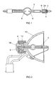
- the structure of a radiation source according to the invention is shown in Fig. 1 using the example of a sectional view of a discharge lamp.
- the discharge lamp consists of a glass or ceramic element 1, in the interior of which a radiation unit 8 is arranged.
- the radiation unit 8 is two electrodes that are surrounded by a gas. But it is also conceivable that the radiation unit 8 is designed, for example, as a filament or as electrodes which are in a vacuum.
- the radiation unit 8 is connected to electrical leads 9.
- the radiation source 8 shown is a, preferably tubular, discharge lamp with two opposite ends, so that the electrical supply line 9 also leads in two opposite directions.
- the discharge lamp shown has a support element 2a, which is designed as a metallic or ceramic base.
- metal foam 4 which connects the glass or ceramic element 1 with the carrier element 2a.
- the metal foam 4 can also connect the electrical supply line 9 within the connection region 3 to the carrier element 2a, for example a metallic base.
- the metal foam 4 can also be used to connect the electrical supply line 9 with a further electrically conductive element within a non-conductive carrier element 2a.
- this connection or the electrical supply line 9 is insulated by a glass or ceramic material at a further electrical supply line or from the metal foam 4 or the carrier element 2a in order to avoid a short circuit during operation of the discharge lamp. This may be necessary, for example, if the radiation source only over a single Has pedestal through which run at least two electrical leads 9, which are needed to power the radiation unit 8 (not shown).
- the metal foam 4 in addition to the function of a thermally conductive joining material also assumes the function of an electrically conductive connection.
- the discharge lamp with a plurality of carrier elements 2 a namely a base 12, a reflector 13 and an end cap 14, is shown in a sectional representation.
- the glass or ceramic element 1 is connected to the base 12 by the metal foam 4.
- the metal foam 4 is also suitable to connect to the reflector 13 and / or the end cap with the base 12, so that an integrated optical system is formed in which all elements are connected to each other by metal foam 4. In certain areas, it may therefore be necessary to electrically insulate the electrical supply lines 9 or the carrier elements 2a which are in contact with the metal foam 4.
- the surface of the entire optical system serves to dissipate the heat generated in the glass or ceramic element 1. This is achieved by the thermal conductivity of the metal foam 4, which is used as a bonding material between the individual components of the optical system. Furthermore, it is possible by the structure and properties of the metal foam 4, to compensate for the different expansion behavior of different materials of the optical system shown.
- FIG. 3 a sectional view of the glass or ceramic element 1 and of the carrier element 2a is shown. Within the connection region 3, the two components are separated by a gap 5 from each other. In the exemplary embodiment shown, furthermore, the glass or ceramic element 1 is provided with an undercut 10, while the carrier element 2 a has a groove 11.
- These connecting elements shown can also be designed differently, the non-positive and / or positive connection properties to support the metal foam 4, when it is introduced into the gap 5.
- connecting elements shown need not necessarily be present on the glass or ceramic element 1 and / or on the carrier elements 2a, since a permanent connection is also made possible exclusively by the cohesive, non-positive and / or positive connection properties of the metal foam.
- the support element 2a may consist of a metallic, ceramic or glass material or of a combination of said materials.
- the carrier element 2a and the glass or ceramic element 1 it must be ensured that these consist of materials whose melting point is equal to or higher than the foaming point of the metal foam 4, since otherwise it would lead to deformation or destruction during introduction of the metal foam 4 the said elements comes.
- the embodiment shown in FIG. 4 differs from the exemplary embodiment shown in FIG. 3 in that the glass or ceramic element 1 and the carrier element 2 a are connected by the metal foam 4, which is introduced into the intermediate space 5 within the connection region 3.
- the metal foam 4 consists for example of tin, zinc, aluminum, copper, iron or a corresponding foamable alloy and has a porous structure.
- the glass or ceramic element 1 and the carrier element 2a are positioned relative to one another. However, it is also possible, after the introduction of the metal foam 4, to position the said elements relative to one another or to carry out a change in position until the solidification of the metal foam 4 commences.
- the glass or ceramic element 1 has a groove 11, while the carrier element 2 a has an undercut 10.
- a foamable starting material 6 is introduced into the intermediate space 5.
- the foamable starting material 6 is for example of an aluminum alloy with a blowing agent, for example titanium hydride.
- the embodiment shown in FIG. 6 differs from the exemplary embodiment shown in FIG. 5 in that the introduced starting material 6 has been activated and has been foamed into the metal foam 4.
- the metal foam 4 fills, as in the embodiment shown in FIG. 4, the gap 5 within the connection region 3 between the glass or ceramic element 1 and the carrier element 2 a.
- the carrier element 2a When choosing the carrier element 2a is to ensure that it consists of a material whose melting point is equal to or higher than the foaming point of the foamable starting material 6.
- the glass or ceramic element 1 and the carrier element 2a are positioned relative to one another. However, it is also possible to change the position of the glass or ceramic element 1 to the carrier element 2a until the solidification of the metal foam 4 begins.
- the metal foam 4 is produced by a melt metallurgical process or by activation of the foamable starting material 6.
- the foamable starting material 6 is preferably produced by a powder metallurgy process, as used, for example, in sintering.
- the activation of the foamable starting material 6 takes place either in a separate device or within the connecting region 3 of the glass or ceramic element 1 or the carrier element 2a or in the intermediate space 5 between the said elements.
- the activation of the foamable starting material 6 preferably takes place by induction, conduction or infrared radiation.
- the carrier element 2a in an outer region at least one receiving element.
- This receiving element is formed for example as an undercut, groove or thread.
- FIG. 7 shows a sectional illustration of the glass or ceramic element 1 in a foaming mold 7.
- the glass or ceramic element 1 is, as already described above, formed.
- the foaming mold 7, in which the glass or ceramic element 1 or the connection region 3 of the glass or ceramic element 1 to be foamed, is positioned, has an image of the support element to be foamed as a negative.
- this includes the imaging of receiving elements, for example undercuts, grooves or threads in the foam mold 7, but on the other hand also the provision of certain areas in the foam mold 7 for other components of the radiation source, such as electrical leads 9 or insulation.
- a foamed support element 2b fills the area between the glass or ceramic element 1 and the foaming mold 7.
- the foamed carrier element 2b can also contain regions which are electrically connected to the electrical supply line 9 and / or the radiation unit 8 or are insulated from these.
- either metal foam 4 is introduced into the foam mold 7, or foamable starting material 6 within the foam mold 7, for example by induction, is activated.
- foamed carrier element 2b Upon solidification of the foamed carrier element 2b, the foamed carrier element 2b is permanently connected to the glass or ceramic element 1.
- the foaming mold 7 may consist of a material that includes the separating function, or consist of a composite system (composite material or foam material-repellent covering layer), which still contains the separating function in addition to the shaping function.
- a split shape can be moved, for example, at an angle to a main axis of the foam body Mold halves are used. After cooling or hardening of the metal foam 4, the radiation source is removed from the foam mold 7.
- FIG. 8 shows a sectional view of the glass or ceramic element 1 with a foamed carrier element 2b which has been removed from the foam mold 7.
- the electrical supply line 9, which is in contact with the radiation unit 8 within the glass or ceramic element 1, is not electrically insulated from it in the present case within the area of the foamed carrier element 2b. Nevertheless, e.g. in the case of several supply lines, such electrical insulation is required or, for other reasons, only desired and realized.
- the outer regions of the foamed carrier element 2b have a higher density and lower porosity than regions of the foamed carrier element 2b, which lie closer to the foamed glass or ceramic element 1. This makes it possible to external recording elements such. B. a receiving thread, faithful to shape and with a higher surface quality.
- the necessary compression of the outer regions of the foamed carrier element 2b can be achieved on the one hand by a corresponding temperature of the foaming mold 7, whereby pores of the metal foam 4 collapse in those adjacent to the foaming mold 7 areas.
- the compression can also take place by means of a heat treatment carried out after demoulding the radiation source and / or mechanical deformation.
- a graduation of the metal foam density can also be realized by the foaming mold material, for example, used in multiple layers and / or used with different propellant contents. Graduation of the metal foam density is further e.g. also possible by combining non-foamable aluminum with foamable molding material (e.g., Al foam).
- the embodiments described above describe a method for producing a radiation source and a radiation source having at least one glass or ceramic element and at least one carrier element, wherein the glass or ceramic element and the carrier element within a connection region are interconnected by metal foam. Furthermore, the embodiments described above describe a method for producing a radiation source and a radiation source having at least one glass or ceramic element and at least one carrier element, wherein the carrier element is a foamed carrier element which consists of metal foam.
Landscapes
- Engineering & Computer Science (AREA)
- Manufacturing & Machinery (AREA)
- Chemical & Material Sciences (AREA)
- Composite Materials (AREA)
- Materials Engineering (AREA)
- Mechanical Engineering (AREA)
- Ceramic Products (AREA)
- Glass Compositions (AREA)
- Physical Or Chemical Processes And Apparatus (AREA)
- Common Detailed Techniques For Electron Tubes Or Discharge Tubes (AREA)
- Manufacture Of Electron Tubes, Discharge Lamp Vessels, Lead-In Wires, And The Like (AREA)
- Vessels And Coating Films For Discharge Lamps (AREA)
Applications Claiming Priority (2)
| Application Number | Priority Date | Filing Date | Title |
|---|---|---|---|
| DE102004063262 | 2004-12-29 | ||
| DE102005001949A DE102005001949B4 (de) | 2004-12-29 | 2005-01-14 | Verfahren zur Herstellung einer Strahlungsquelle und Strahlungsquelle |
Publications (2)
| Publication Number | Publication Date |
|---|---|
| EP1677332A2 true EP1677332A2 (fr) | 2006-07-05 |
| EP1677332A3 EP1677332A3 (fr) | 2009-12-09 |
Family
ID=36123296
Family Applications (1)
| Application Number | Title | Priority Date | Filing Date |
|---|---|---|---|
| EP05027023A Withdrawn EP1677332A3 (fr) | 2004-12-29 | 2005-12-09 | Procédé de fabrication d'une source de rayonnement |
Country Status (7)
| Country | Link |
|---|---|
| US (1) | US20060141894A1 (fr) |
| EP (1) | EP1677332A3 (fr) |
| JP (1) | JP2006190677A (fr) |
| KR (1) | KR20060076232A (fr) |
| CN (1) | CN1870206B (fr) |
| CA (1) | CA2531611A1 (fr) |
| DE (1) | DE102005001949B4 (fr) |
Cited By (6)
| Publication number | Priority date | Publication date | Assignee | Title |
|---|---|---|---|---|
| WO2008019874A1 (fr) * | 2006-08-18 | 2008-02-21 | Fraunhofer-Gesellschaft zur Förderung der angewandten Forschung e.V. | Procédé et semi-produit pour l'assemblage de pièces |
| WO2008145173A1 (fr) * | 2007-05-25 | 2008-12-04 | Osram Gesellschaft mit beschränkter Haftung | Lampe électrique dotée d'une ampoule et procédé de fabrication d'une lampe électrique |
| WO2009046750A1 (fr) * | 2007-10-02 | 2009-04-16 | Osram Gesellschaft mit beschränkter Haftung | Culot de lampe à décharge et procédé de fabrication d'un culot de lampe à décharge |
| WO2010130544A1 (fr) * | 2009-05-15 | 2010-11-18 | Osram Gesellschaft mit beschränkter Haftung | Lampe à décharge sous haute pression dotée d'un élément de refroidissement |
| EP3121659A1 (fr) * | 2015-07-24 | 2017-01-25 | The Swatch Group Research and Development Ltd. | Assemblage de piece en materiau fragile |
| EP3120954A1 (fr) * | 2015-07-24 | 2017-01-25 | The Swatch Group Research and Development Ltd. | Methode de revetement de piece |
Families Citing this family (4)
| Publication number | Priority date | Publication date | Assignee | Title |
|---|---|---|---|---|
| JP5268026B2 (ja) * | 2009-03-04 | 2013-08-21 | 岩崎電気株式会社 | 外管付きランプ |
| JP6195393B1 (ja) * | 2016-03-23 | 2017-09-13 | ウィンボンド エレクトロニクス コーポレーション | 出力回路 |
| EP3653740B1 (fr) * | 2017-07-14 | 2024-12-25 | Japan Science and Technology Agency | Procédé de production de mousse métallique |
| CN109543288B (zh) * | 2018-11-16 | 2020-10-16 | 中国舰船研究设计中心 | 基于突变拓扑态的高功率辐射源设计方法 |
Family Cites Families (11)
| Publication number | Priority date | Publication date | Assignee | Title |
|---|---|---|---|---|
| NL108778C (fr) * | 1958-08-23 | |||
| US3336134A (en) * | 1960-12-14 | 1967-08-15 | Gen Electric | Foam material |
| US3214265A (en) * | 1963-03-11 | 1965-10-26 | Lor Corp | Method of making metal foam bodies |
| NL6609881A (fr) * | 1966-07-14 | 1968-01-15 | ||
| US5374872A (en) * | 1992-11-13 | 1994-12-20 | General Electric Company | Means for supporting and sealing the lead structure of a lamp and method for making such lamp |
| NO311708B1 (no) * | 2000-02-25 | 2002-01-14 | Cymat Corp | Fremgangsmåte og utstyr for tildannelse av stöpte produkter |
| DE10053763C2 (de) * | 2000-10-30 | 2002-10-17 | Pilz Gmbh & Co | Feldbussystem zum Steuern von sicherheitskritischen Prozessen sowie Busanschaltmodul zur Verwendung in einem solchen Feldbussystem |
| US6706239B2 (en) * | 2001-02-05 | 2004-03-16 | Porvair Plc | Method of co-forming metal foam articles and the articles formed by the method thereof |
| US6650033B2 (en) * | 2001-08-06 | 2003-11-18 | Tyco Electronics Corporation | Foamable coupling for lamp assembly and methods for using the coupling |
| DE10220735A1 (de) * | 2002-05-08 | 2003-11-20 | Patent Treuhand Ges Fuer Elektrische Gluehlampen Mbh | Verfahren zum Herstellen einer Metall-Keramik-Verbindung |
| US20050249602A1 (en) * | 2004-05-06 | 2005-11-10 | Melvin Freling | Integrated ceramic/metallic components and methods of making same |
-
2005
- 2005-01-14 DE DE102005001949A patent/DE102005001949B4/de not_active Expired - Fee Related
- 2005-12-09 EP EP05027023A patent/EP1677332A3/fr not_active Withdrawn
- 2005-12-13 US US11/299,684 patent/US20060141894A1/en not_active Abandoned
- 2005-12-23 CA CA002531611A patent/CA2531611A1/fr not_active Abandoned
- 2005-12-28 JP JP2005379679A patent/JP2006190677A/ja active Pending
- 2005-12-28 KR KR1020050131341A patent/KR20060076232A/ko not_active Withdrawn
- 2005-12-29 CN CN2005101378615A patent/CN1870206B/zh not_active Expired - Fee Related
Cited By (11)
| Publication number | Priority date | Publication date | Assignee | Title |
|---|---|---|---|---|
| WO2008019874A1 (fr) * | 2006-08-18 | 2008-02-21 | Fraunhofer-Gesellschaft zur Förderung der angewandten Forschung e.V. | Procédé et semi-produit pour l'assemblage de pièces |
| WO2008145173A1 (fr) * | 2007-05-25 | 2008-12-04 | Osram Gesellschaft mit beschränkter Haftung | Lampe électrique dotée d'une ampoule et procédé de fabrication d'une lampe électrique |
| WO2009046750A1 (fr) * | 2007-10-02 | 2009-04-16 | Osram Gesellschaft mit beschränkter Haftung | Culot de lampe à décharge et procédé de fabrication d'un culot de lampe à décharge |
| WO2010130544A1 (fr) * | 2009-05-15 | 2010-11-18 | Osram Gesellschaft mit beschränkter Haftung | Lampe à décharge sous haute pression dotée d'un élément de refroidissement |
| US8519623B2 (en) | 2009-05-15 | 2013-08-27 | Osram Gmbh | High-pressure discharge lamp having a cooling element |
| EP3121659A1 (fr) * | 2015-07-24 | 2017-01-25 | The Swatch Group Research and Development Ltd. | Assemblage de piece en materiau fragile |
| EP3120954A1 (fr) * | 2015-07-24 | 2017-01-25 | The Swatch Group Research and Development Ltd. | Methode de revetement de piece |
| WO2017016951A1 (fr) * | 2015-07-24 | 2017-02-02 | The Swatch Group Research And Development Ltd | Methode de revetement de piece |
| WO2017016950A1 (fr) * | 2015-07-24 | 2017-02-02 | The Swatch Group Research And Development Ltd | Assemblage de piece en materiau fragile |
| US10933470B2 (en) | 2015-07-24 | 2021-03-02 | The Swatch Group Research And Development Ltd | Assembling a part made of brittle material |
| US11167349B2 (en) | 2015-07-24 | 2021-11-09 | The Swatch Group Research And Development Ltd | Part coating method |
Also Published As
| Publication number | Publication date |
|---|---|
| US20060141894A1 (en) | 2006-06-29 |
| CA2531611A1 (fr) | 2006-06-29 |
| EP1677332A3 (fr) | 2009-12-09 |
| DE102005001949B4 (de) | 2006-10-26 |
| CN1870206A (zh) | 2006-11-29 |
| JP2006190677A (ja) | 2006-07-20 |
| DE102005001949A1 (de) | 2006-07-13 |
| KR20060076232A (ko) | 2006-07-04 |
| CN1870206B (zh) | 2011-08-03 |
Similar Documents
| Publication | Publication Date | Title |
|---|---|---|
| DE3874782T2 (de) | Sicherung mit umhuellung aus fester keramik hoher dichte und herstellungsverfahren dieser sicherung. | |
| DE3620373A1 (de) | Elektrische gluehlampe fuer reihenschaltung und verfahren zu ihrer herstellung | |
| DE4124071C2 (de) | Entladungslampeneinheit | |
| DE102005001949B4 (de) | Verfahren zur Herstellung einer Strahlungsquelle und Strahlungsquelle | |
| DE2647623A1 (de) | Abdichtende elektrische anschlussklemme und verfahren zu deren herstellung | |
| DE3328975A1 (de) | Verfahren zum hartverloeten zweier bauteile mit unterschiedlichen waermeleitfaehigkeiten und hartgeloetetes schaltungsflachgehaeuse | |
| EP3436261B1 (fr) | Procédé de fabrication d'un isolateur céramique | |
| EP1183697B1 (fr) | Soufflet pour condensateur a vide ayant une couche electriquement conductrice reguliere | |
| DE3616673A1 (de) | Halogengluehlampe | |
| AT408299B (de) | Heizvorrichtung für elektrische heizplatten, zündeinrichtungen, temperatursensoren od. dgl. | |
| DE4014745A1 (de) | Einseitig gesockelte elektrische lampe | |
| DE10290590B4 (de) | Verfahren zur Herstellung eines Bogenentladungsröhrenkörpers | |
| DE2737931C2 (de) | Endverschluß für eine Entladungslampe | |
| EP3108489B1 (fr) | Broche de contact, contact tubulaire et procédé de production | |
| EP1481574B1 (fr) | Procede de fabrication d'un element electrode pour chalumeau a plasma | |
| DE10257477B4 (de) | Blitzlampe bildender Verbundkörper und Verfahren zum Herstellen eines eine Blitzlampe bildenden Verbundkörpers | |
| DE2758706A1 (de) | Mikrowellen-magnetron und verfahren zu seiner herstellung | |
| DE2646498C2 (de) | Elektronenstrahlauffänger, insb. für Laufzeitröhren, und Verfahren zu seiner Herstellung | |
| EP1897115A1 (fr) | Systeme d'electrode pour une lampe | |
| DE102010017710A1 (de) | Trägerelement für LED-Modul | |
| DE69819669T2 (de) | Leuchtstofflampe | |
| EP1178519B1 (fr) | Ampoule en quartz avec au moins une traversée éléctrique, procédé pour la fabrication d'une connexion étanche aux gaz entre les deux, et son utilisation dans une lampe à décharge | |
| WO2008145173A1 (fr) | Lampe électrique dotée d'une ampoule et procédé de fabrication d'une lampe électrique | |
| DE112008001624T5 (de) | Hochintensitätsentladungslampe mit verbesserten Dimmeigenschaften | |
| DE69013595T2 (de) | Verfahren zur Herstellung einer gasverschmolzenen Entladungsröhre. |
Legal Events
| Date | Code | Title | Description |
|---|---|---|---|
| PUAI | Public reference made under article 153(3) epc to a published international application that has entered the european phase |
Free format text: ORIGINAL CODE: 0009012 |
|
| AK | Designated contracting states |
Kind code of ref document: A2 Designated state(s): AT BE BG CH CY CZ DE DK EE ES FI FR GB GR HU IE IS IT LI LT LU LV MC NL PL PT RO SE SI SK TR |
|
| AX | Request for extension of the european patent |
Extension state: AL BA HR MK YU |
|
| PUAL | Search report despatched |
Free format text: ORIGINAL CODE: 0009013 |
|
| AK | Designated contracting states |
Kind code of ref document: A3 Designated state(s): AT BE BG CH CY CZ DE DK EE ES FI FR GB GR HU IE IS IT LI LT LU LV MC NL PL PT RO SE SI SK TR |
|
| AX | Request for extension of the european patent |
Extension state: AL BA HR MK YU |
|
| AKY | No designation fees paid | ||
| STAA | Information on the status of an ep patent application or granted ep patent |
Free format text: STATUS: THE APPLICATION IS DEEMED TO BE WITHDRAWN |
|
| 18D | Application deemed to be withdrawn |
Effective date: 20100610 |
|
| REG | Reference to a national code |
Ref country code: DE Ref legal event code: 8566 |