EP1677407B1 - Etranglement à courant circulant - Google Patents
Etranglement à courant circulant Download PDFInfo
- Publication number
- EP1677407B1 EP1677407B1 EP06100076.6A EP06100076A EP1677407B1 EP 1677407 B1 EP1677407 B1 EP 1677407B1 EP 06100076 A EP06100076 A EP 06100076A EP 1677407 B1 EP1677407 B1 EP 1677407B1
- Authority
- EP
- European Patent Office
- Prior art keywords
- sub
- conductors
- conductor
- compensator
- winding
- Prior art date
- Legal status (The legal status is an assumption and is not a legal conclusion. Google has not performed a legal analysis and makes no representation as to the accuracy of the status listed.)
- Expired - Lifetime
Links
Images




Classifications
-
- H—ELECTRICITY
- H02—GENERATION; CONVERSION OR DISTRIBUTION OF ELECTRIC POWER
- H02K—DYNAMO-ELECTRIC MACHINES
- H02K11/00—Structural association of dynamo-electric machines with electric components or with devices for shielding, monitoring or protection
-
- H—ELECTRICITY
- H02—GENERATION; CONVERSION OR DISTRIBUTION OF ELECTRIC POWER
- H02K—DYNAMO-ELECTRIC MACHINES
- H02K3/00—Details of windings
- H02K3/04—Windings characterised by the conductor shape, form or construction, e.g. with bar conductors
- H02K3/18—Windings for salient poles
- H02K3/20—Windings for salient poles for auxiliary purposes, e.g. damping or commutating
Definitions
- the present invention relates to a compensator to be used for minimizing circulatory current losses in connection with the winding of an electric machine, the compensator comprising a frame part made of a magnetically conductive material and a winding formed in the frame part and provided with at least one conductor comprising at least two sub-conductors.
- the present invention relates to an electric machine with a stator comprising a winding with at least one conductor comprising at least two sub-conductors, a compensator being installed in connection with the winding.
- a rotating electric machine consists of a stator and a rotor.
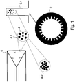
- the stator 3 of the electric machine is provided with grooves 3.1 in which conductors 4 are installed ( Fig. 1 ).
- the conductors normally consist of several parallel sub-conductors 4.1 to facilitate the manufacture and to reduce losses caused by the skin effect.
- a current interchange takes place through loops formed by sub-conductors 4.1, causing so-called circulatory currents in these loops.
- the currents of all the sub-conductors are not in the same phase, and their amplitudes are not equal.
- so-called differential-mode currents flow along the sub-conductors in addition to the common-mode current.
- the resistive losses of the whole conductor 4 are greater than in a case in which the same total current is evenly distributed in all the sub-conductors 4.1. This problem is particularly manifested in machines with a high input frequency. The extra resistive losses due to the circulatory currents cause heating of the winding and limit the power output from the machine.
- the circulatory currents are eliminated, if the winding can be made in such a way that the total flow through the loops formed by the parallel sub-conductors 4.1 is zero.
- the position of each sub-conductor 4.1 in the groove is designed in advance, and the winding is implemented by using so-called Roebel rods in such a way that the total flow of the sub-conductor loops is eliminated almost totally. In smaller machines, however, this is not a practical solution.
- the conductors may be divided into several parallel conductors, and the position of these conductors may be alternating in the grooves. This reduces the extra losses caused by the problem of circulatory currents but increases the amount of work in the production.
- Litz wire consists of a large number of thin parallel wires that are braided or twisted. Such a Litz wire is illustrated by a sub-conductor indicated with the reference 4.2 in Fig. 1 .
- the structure of the Litz wire eliminates efficiently the total fluxes passing through the loops formed by its internal wires; in other words, a similar current flows through all the strands of a single Litz wire.
- the optimum solution would be to make the whole conductor of a single thick Litz wire. In practice, the conductors must be made of several parallel Litz wires, because it is difficult to insert a single thick conductor in a groove.
- the extra losses caused by the circulatory currents may also be reduced by the design of the grooves and by instructions relating to the production of the winding.
- the patent specification GB 797,279 relates to conductor arrangements of an alternating current furnace that has, however, significantly different electrical characteristics than those of a rotating electrical machine.
- the currents flowing in four or more parallel connected conductors supplying alternating current to a furnace are equalized by an iron core having a number of holes through which the conductors pass in pairs in such a manner that the magnetic field of one conductor of a pair opposes the field of the other conductor, and all but two of the conductors each traverse two holes, whereby it is magnetically coupled with each of the two neighbouring conductors, so that all the conductors are linked together in a magnetic chain.
- the two end conductors of the chain each traverse one hole only and are thus only coupled to one other conductor.
- Each conductor may comprise a group of smaller conductors.
- the impedances of the several conductors are preferably arranged to be as equal as possible and the parallel connections are made only at their ends.
- the invention is based on the idea that one or more compensators are coupled to the stator winding of the electric machine to provide a structure to compensate for the differential currents of sub-conductors without causing significant inductance in the common-mode current of the sub-conductors.
- the compensator is used as a kind of choke (filter) for the circulatory currents by causing inductance in the differential-mode currents (circulatory currents).
- the choke according to the present invention applies a frame that is magnetically well conducting and is provided with openings, through which the sub-conductors are led in such a way that in a situation in which an equal current flows along all the sub-conductors, the total current in each opening is substantially zero.
- Suitable frame materials include, for example, armature sheets used in electric machines, ferrite materials, powder metals and amorphous sheets. What is essential is that the material has good relative permeability, a high saturating flux density and small losses. Consequently, the sub-conductors are placed in the openings in such a way that the total flux in each opening is substantially zero when the currents flowing along all the sub-conductors are equal.
- each opening must contain at least two different sub-conductors, and each sub-conductor is led preferably several times through the openings.
- the expression of the total current in each opening is a linear combination of the currents of the sub-conductors.
- the choke To force the current of all the NS sub-conductors to be substantially equal, the choke must contain at least NS - 1 openings. The total currents of the openings make up NS -1 expressions.
- the sub-conductors must be inserted in the openings in such a way that when these expressions are marked to be zero, the only solution to the formed set of equations is the fact that the currents of all the sub-conductors are equal.
- the present invention shows remarkable advantages over solutions of prior art.
- the arrangement of the invention it is possible to eliminate the extra losses caused by circulatory currents almost totally. In this way it is possible to maximize the output of the machine and to minimize the temperatures of the winding.
- the stator winding can be made simple and inexpensive, because the circulatory current phenomenon does not need to be taken into account in the design of the structure of the winding. Windings are often made manually, wherein the stators become unique in view of the circulatory currents. This means that there is a deviation in the quantity of their resistive losses. When a choke is used, such a deviation is significantly reduced or even eliminated, and in all the stators, the quantity of resistive losses is close to the theoretical minimum.
- the required size of the choke is a fraction of the size of the stator of the electric machine.
- the plates needed for the choke can be made, for example, of the extra pieces left over from die-cutting of the armature sheets of the stator or rotor of the electric machine.
- the frame 2 of the compensator 1 is a structure consisting of two parts.
- the first part 2.1 of the frame is intended for a winding
- the second part 2.2 is intended, together with the part 2.1, to form openings with a closed magnetic circuit in the compensator.
- the first part 2.1 and the second part 2.2 of the frame are made of, for example, iron sheets used in the manufacture of the stator 3.
- the first frame part 2.1 is provided with a cogging for the winding of the compensator.
- the cogging comprises preferably as many cogs 2.12 as there are parallel sub-conductors 4.1 in the conductors 4 of the stator winding.
- the number of cogs 2.12 is seven, because the winding 6 of the corresponding stator 3 consists of conductors with 7 sub-conductors, but it is obvious that the invention is not limited to such an application, but the number of sub-conductors 4.1 of the winding may also be other than seven.
- the coils of the winding 6 may also consist of several conductors 4.
- Grooves 2.11 are formed for the winding of the compensator between the cogs 2.12 of the first frame part 2.1 of the compensator.
- Each sub-conductor 4.1 of the conductor 4 of the stator winding is wound the same number of turns around its respective cog 2.12; in other words, the sub-conductor 4.1 is inserted in two adjacent grooves 2.11.
- This placement of the sub-conductors 4.1 around the different cogs is illustrated by Fig. 3b .
- the compensator does not substantially resist the common-mode current.
- the currents flowing along the sub-conductors wound in the same groove do not have the same amplitude or the same phase, they do not compensate for each other. This difference in the currents provides a total current different from zero and a magnetomotive force in the magnetic circuit surrounding the opening 5 connected to the groove, which force, in turn, resists the flowing of the differential-mode current according to Lenz's law.
- the operation of the chokes may be made more effective by increasing the number of laps around the cogs or by increasing the surface area of the cogs. Experiments have shown that good results can be achieved by a winding of only two or three laps. Normally, a winding of four to six laps per sub-conductor will be sufficient.
- the efficiency of the compensation is directly affected by the surface area of the cogs of the choke and the air space between the first part 2.1 and the second part 2.2. The larger the surface area of the cog and the smaller the air space, the more efficient the compensation.
- it can be secured by simulation that the maximum values of the flux density in the magnetic circuit of the choke remain within the linear range of the material, because saturation of the magnetic circuit will result in impaired compensation.
- the coils of the compensator 1 are formed in such a way that the winding of each sub-conductor is started and ended at the same end of the cog in question.
- the coil will have a half lap in addition to the whole laps, which produces a slight inductance in the common-mode current as well.
- This kind of a structure may be used if there is also a need for common-mode inductance.
- Figures 4a and 4b show a modification of the invention, in which planar sheets 2.3, 2.4 are provided with cogs 2.32, 2.42.
- the sub-conductors 4.1 are placed in the spaces 2.31, 2.41 between the cogs in such a way that exactly one sub-conductor 4.1 extends through each space.
- the second planar sheet 2.4 is turned onto the first planar sheet 2.3, wherein openings are formed, two sub-conductors extending in each of the openings and currents flowing in different directions in the sub-conductors.
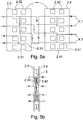
- Figures 5a and 5b show a modification of the structure of Figs. 4a and 4b .
- the cogs of Figs. 4a and 4b are divided into several smaller cogs, wherein the number of openings 5 is significantly increased.
- the frame 2 of the compensator 1 comprises two preferably identical sheet-like elements 2.3, 2.4 with cogs 2.32, 2.42.
- the sub-conductors 4.1 of the conductor 4 are placed in spaces 2.31, 2.41 between the cogs, for example in a stepwise manner as shown.
- Figure 5a shows four sub-conductors 4.1 placed in the spaces 2.32, 2.41 between the cogs 2.32, 2.42.
- the elements 2.3, 2.4 of the frame 2 of the compensator can be placed against each other so that the cogs of both elements 2.3, 2.4 are substantially against each other.
- the structure of Fig. 5b is formed, comprising a large number of openings 5.
- Yet another example on manufacturing the choke is a method in which a magnetic piece is provided, for example by drilling, with holes, through which the sub-conductors are inserted by applying the above-presented principle in such a way that the sum of the currents flowing in each hole is to be zero, when the currents in all the sub-conductors extending through the opening are equal.
- the compensator according to the invention may also be manufactured in such a way that in connection with the manufacture, the magnetic circuit of the stator 3 is provided with a perforation, a cogging or a set of openings implemented in another way, in connection with which the sub-conductors 4.1 can be placed.
- Each conductor 4 of the electric machine, for which compensation is to be provided, is equipped with a respective compensator 1.
- three different compensators 1 are needed, their structures being preferably substantially equal.
- the winding of each compensator 1 is formed, for example, of the winding of the stator, either at the initial end or the terminal end.
- a sufficient free length of the conductor is left at one end of each conductor of the stator.
- the sub-conductors of this conductor left free are wound to the compensator 1 in the above-described manner.
- the sub-conductors 4.1 of three conductors 4 are wound to three compensators 1.
- the compensator may also be manufactured as a component separate from the manufacture of the stator.
- the choke and the stator are wound from the own sub-conductors in the above-described manner, and finally the sub-conductors of the stator and the choke are connected to each other, for example by welding or by crimped connections.
- stator 3 of an electric machine, in which the number of sub-conductors of the conductor is greater than the number of openings 5 in the compensator 1, or there is another reason for reducing the number of sub-conductors to be handled separately.
- the stator 3 is wound by a method known as such but in such a way that at least one end of the coils of the different phases is provided with a sufficient free length of the conductor 4, whose sub-conductors 4.1 can be wound to the compensator 1.
- the above-mentioned separate compensator can be used.
- the currents in the different sub-conductors of the windings of different phases are measured by, for example, a clip-on current meter.
- a sinusoidal current is supplied to the stator.
- the sub-conductors are divided into groups in such a way that those sub-conductors, whose currents are close to each other with respect to the amplitude and the phase, are bundled into a group of their own and they are handled as one sub-conductor during the winding of the compensator.
- Each group should contain substantially the same number of sub-conductors.
- the above-mentioned division into groups may be implemented for example in the following way: After the measurement of the sub-conductors, the currents of the sub-conductors of each conductor are drawn on their respective complex plane.
- Figure 6a shows the currents of the sub-conductors of one phase of a stator, drawn on a complex plane.
- the number of sub-conductors is 56.
- the amplitude and the angle of phase of the complex number indicate the amplitude and the phase of the current of the sub-conductor in question, respectively.
- the measurement results are searched for those two sub-conductors whose currents are farthest away from each other in the complex plane (connected with a solid line 601 in Fig. 6a ).
- the complex plane is then divided into a desired number of ranges (in this case, 7 groups and ranges) by drawing lines (broken lines 602 in Fig. 6a ) substantially perpendicular to said line in such a way that the same number of measurement results of sub-conductors always remain between two successive lines.
- the sub-conductors remaining between two adjacent lines are bundled together.
- Figure 6a shows the distribution of currents without the compensator
- Fig. 6b shows the distribution of currents when the groups of sub-conductors have been wound to the compensator of Fig. 3 .
- the loss coefficient k without the compensator is about 1.14; in other words, the stator has about 14% extra copper losses due to circulatory currents when compared with the theoretical minimum.
- the loss coefficient k is about 1.03; that is, the quantity of extra losses is only about 3%. In practice, this is a good result. If the number of sub-conductors is not divisible by the number of cogs, some of the sub-conductors (preferably those sub-conductors whose current without the compensator is close to the average current) may be left unwound to the choke in such a way that the number of sub-conductors to be wound to the choke is divisible by the number of cogs. On the other hand, a sufficiently good result may be achieved even if each group did not contain the same number of sub-conductors.
- the openings needed in the circulatory current choke may be implemented by using commercially available transformer cores, such as E-cores, toroid cores, or the like.
- Figure 7 shows the compensator made in such a way that the sub-conductors of the conductor, in this case 4 in number, are divided by the above-presented grouping method into two groups of two sub-conductors, and the groups are wound around one toroid.
- a circulatory current choke with more openings could be implemented with several toroids.
- the compensator consists of grooves, in which the sub-conductors are placed in substantially the same order in which the perpendicular projections of the measurement results corresponding to the sub-conductors of Fig. 6 coincide with the line 601.
- one coil is formed by one conductor 4.
- the compensator 1 may also be applied in a case in which a coil consists of several conductors. In such a case, a separate compensator may be used in connection with each conductor, or parallel conductors may be treated as one conductor, in which one common compensator is installed.
- the applicability of the compensator is not limited to the above-described three-phase winding 6 coupled to a triangle, but the compensator may also be applied in an alternating current electric machine, in which the number of phases is other than three and whose coupling is other than a triangle. Furthermore, the applicability of the compensator is not limited by the placement of the conductor turns of the stator winding in the grooves of the stator.
- the compensator 1 in only a part of the phases.
- the choke is constructed in such a way that with a given total current of the conductor, the energy of the magnetic circuit achieves a minimum, when the current flowing along all the sub-conductors is substantially equal.
Landscapes
- Engineering & Computer Science (AREA)
- Power Engineering (AREA)
- Windings For Motors And Generators (AREA)
- Linear Motors (AREA)
- Iron Core Of Rotating Electric Machines (AREA)
Claims (5)
- Une machine électrique rotative comprenant un stator (3) comprenant un enroulement (6) comprenant au moins un conducteur (4) comprenant un premier sous-conducteur et un deuxième sous-conducteur (4.1), dans laquelle le premier et le deuxième sous-conducteur sont connectés en parallèle ; caractérisé en ce que ledit enroulement (6) est pourvu avec au moins un compensateur (1) pour minimiser les pertes de courant circulatoire de l'enroulement (6) de la machine électrique, le compensateur (1) comprenant une partie de cadre (2) en un matériau magnétiquement conducteur et étant pourvu d'au moins une ouverture (5) ; lesdits premier et deuxième sous-conducteurs (4.1) étant disposés de manière à s'étendre géométriquement en anti-parallèle à travers la au moins une ouverture (5) de sorte que le courant total circulant à travers l'ouverture (5) est sensiblement nul, lorsque le courant alternatif fourni au premier sous-conducteur est égal au courant fourni au deuxième sous-conducteur.
- La machine électrique rotative selon la revendication 1, dans laquelle ladite au moins une ouverture (5) a été pourvu en formant la partie de cadre (2) du compensateur (1) de deux pièces (2.1, 22, 2.3, 2.4) équipé d'au moins un premier et un deuxième pignon (2.12, 2.32, 2.42) de telle manière que lorsque les pièces (2.1, 2.2, 2.3, 2.4) de la partie de cadre (2) sont jointes, lesdites au moins une ou plusieurs ouvertures (5) sont formées dans la partie de cadre (2).
- La machine électrique rotative selon la revendication 1, dans laquelle ladite au moins une ouverture (5) a été formée dans la partie de cadre (2) du compensateur par perçage ou poinçonnage.
- La machine électrique rotative selon la revendication 1, dans laquelle ladite au moins une ouverture (5) a été formée en pourvoyant la partie de cadre (2) du compensateur d'une ou plusieurs rainures.
- La machine électrique rotative selon l'une des revendications 1 à 4, dans laquelle chaque sous-conducteur (4.1) du conducteur est constitué d'un fil massif ou d'un toron.
Applications Claiming Priority (1)
| Application Number | Priority Date | Filing Date | Title |
|---|---|---|---|
| FI20055006A FI117732B (fi) | 2005-01-04 | 2005-01-04 | Kiertovirtakuristin |
Publications (3)
| Publication Number | Publication Date |
|---|---|
| EP1677407A2 EP1677407A2 (fr) | 2006-07-05 |
| EP1677407A3 EP1677407A3 (fr) | 2009-09-16 |
| EP1677407B1 true EP1677407B1 (fr) | 2020-09-09 |
Family
ID=34112657
Family Applications (1)
| Application Number | Title | Priority Date | Filing Date |
|---|---|---|---|
| EP06100076.6A Expired - Lifetime EP1677407B1 (fr) | 2005-01-04 | 2006-01-04 | Etranglement à courant circulant |
Country Status (4)
| Country | Link |
|---|---|
| US (1) | US7750526B2 (fr) |
| EP (1) | EP1677407B1 (fr) |
| ES (1) | ES2820326T3 (fr) |
| FI (1) | FI117732B (fr) |
Families Citing this family (3)
| Publication number | Priority date | Publication date | Assignee | Title |
|---|---|---|---|---|
| US7876016B2 (en) * | 2007-11-15 | 2011-01-25 | Sundyne Corporation | Stator winding method and apparatus |
| FI122723B (fi) * | 2007-12-03 | 2012-06-15 | Kemira Oyj | Koostumus ja menetelmä puun käsittelemiseksi |
| DE102013206558A1 (de) * | 2013-04-12 | 2014-10-16 | Robert Bosch Gmbh | Steckverbindung mit fixierter Leitung |
Citations (1)
| Publication number | Priority date | Publication date | Assignee | Title |
|---|---|---|---|---|
| US20020130578A1 (en) * | 2001-03-15 | 2002-09-19 | Tatsuya Anma | Permanent magnet type three-phase AC rotary electric machine |
Family Cites Families (14)
| Publication number | Priority date | Publication date | Assignee | Title |
|---|---|---|---|---|
| US1787133A (en) * | 1925-03-20 | 1930-12-30 | Ilg Electric Ventilating Co | Means for regulating the speed of induction motors |
| GB797279A (en) | 1954-03-12 | 1958-07-02 | Christiania Spigerverk | Improvements in or relating to alternating current electric furnaces |
| GB1101857A (en) | 1965-09-28 | 1968-01-31 | Black & Decker Ltd | Interference suppression choke |
| US3683271A (en) * | 1970-06-23 | 1972-08-08 | Tatsuo Kobayashi | Power supply filter for noise suppression |
| FR2315189A1 (fr) * | 1975-06-17 | 1977-01-14 | Pont A Mousson | Moteur a reluctance variable |
| US3996537A (en) * | 1975-07-21 | 1976-12-07 | Corcom, Inc. | Noise suppression filter |
| JPS5271156A (en) | 1975-12-11 | 1977-06-14 | Tdk Corp | Power input line filter coil |
| US4403401A (en) * | 1978-09-15 | 1983-09-13 | General Electric Company | Method of making a dynamoelectric machine stator having concentric amorphous metal laminations |
| US5015903A (en) * | 1988-08-15 | 1991-05-14 | Pacific Scientific Company | Electronically commutated reluctance motor |
| US4975672A (en) * | 1989-11-30 | 1990-12-04 | The United States Of America As Represented By The Administrator Of The National Aeronautics And Space Administration | High power/high frequency inductor |
| JP3317045B2 (ja) * | 1994-10-14 | 2002-08-19 | 株式会社村田製作所 | コモンモードチョークコイル |
| JP2003125569A (ja) * | 2001-08-08 | 2003-04-25 | Matsushita Electric Ind Co Ltd | ブラシレスモータ |
| US6965183B2 (en) * | 2003-05-27 | 2005-11-15 | Pratt & Whitney Canada Corp. | Architecture for electric machine |
| DE10343293B4 (de) * | 2003-09-18 | 2009-06-10 | Siemens Ag | Elektrische Maschine mit Dämpfungseinrichtung |
-
2005
- 2005-01-04 FI FI20055006A patent/FI117732B/fi active IP Right Grant
-
2006
- 2006-01-04 EP EP06100076.6A patent/EP1677407B1/fr not_active Expired - Lifetime
- 2006-01-04 ES ES06100076T patent/ES2820326T3/es not_active Expired - Lifetime
- 2006-01-04 US US11/324,345 patent/US7750526B2/en active Active
Patent Citations (1)
| Publication number | Priority date | Publication date | Assignee | Title |
|---|---|---|---|---|
| US20020130578A1 (en) * | 2001-03-15 | 2002-09-19 | Tatsuya Anma | Permanent magnet type three-phase AC rotary electric machine |
Also Published As
| Publication number | Publication date |
|---|---|
| US7750526B2 (en) | 2010-07-06 |
| EP1677407A2 (fr) | 2006-07-05 |
| ES2820326T3 (es) | 2021-04-20 |
| FI20055006L (fi) | 2006-07-05 |
| FI20055006A0 (fi) | 2005-01-04 |
| EP1677407A3 (fr) | 2009-09-16 |
| US20060148313A1 (en) | 2006-07-06 |
| FI117732B (fi) | 2007-01-31 |
Similar Documents
| Publication | Publication Date | Title |
|---|---|---|
| CN103930958B (zh) | 用于分裂铁芯构造的缠绕式铁芯制造方法 | |
| JP4800451B1 (ja) | 高周波トランス | |
| US9633776B2 (en) | Variable core electromagnetic device | |
| Vetuschi et al. | Minimization of proximity losses in electrical machines with tooth-wound coils | |
| US6617950B2 (en) | Common mode/differential mode choke | |
| CN1333414C (zh) | 电感器装置和其电感器构架 | |
| JP5824211B2 (ja) | 複合磁気部品及びそれを用いたスイッチング電源装置 | |
| CN103578704A (zh) | 线性电磁装置 | |
| CN105895328B (zh) | 三相五柱式铁芯和静止电磁设备 | |
| CN101578672A (zh) | 兼有电抗器式变压器 | |
| CN105762947A (zh) | 电枢、用于电枢的端部模块和用于装配电枢的方法 | |
| CN101179210B (zh) | 旋转电机的电枢绕组 | |
| RU2082245C1 (ru) | Многофазный трансформатор | |
| WO2014167571A1 (fr) | Bobines d'arrêt triphasées et leurs procédés de fabrication | |
| US7750526B2 (en) | Circulatory current choke | |
| US20220108823A1 (en) | Inductor | |
| US20150279549A1 (en) | Systems and methods for promoting low loss in parallel conductors at high frequencies | |
| CN209357573U (zh) | 三相电抗器的电感平衡磁芯及三相电抗器 | |
| CN211858327U (zh) | 电感结构、电抗装置和变压装置 | |
| CN116031051A (zh) | 变压器 | |
| US20230033439A1 (en) | Electrotechnical device for an aircraft | |
| KR200203543Y1 (ko) | 철심자로에 공극을 갖는 리액터 구조 | |
| CN111524686B (zh) | 电感结构、电抗装置和变压装置 | |
| EP0844626B1 (fr) | Transformateur | |
| RU2584821C1 (ru) | Управляемый электрический реактор с поперечным подмагничиванием |
Legal Events
| Date | Code | Title | Description |
|---|---|---|---|
| PUAI | Public reference made under article 153(3) epc to a published international application that has entered the european phase |
Free format text: ORIGINAL CODE: 0009012 |
|
| AK | Designated contracting states |
Kind code of ref document: A2 Designated state(s): AT BE BG CH CY CZ DE DK EE ES FI FR GB GR HU IE IS IT LI LT LU LV MC NL PL PT RO SE SI SK TR |
|
| AX | Request for extension of the european patent |
Extension state: AL BA HR MK YU |
|
| PUAL | Search report despatched |
Free format text: ORIGINAL CODE: 0009013 |
|
| AK | Designated contracting states |
Kind code of ref document: A3 Designated state(s): AT BE BG CH CY CZ DE DK EE ES FI FR GB GR HU IE IS IT LI LT LU LV MC NL PL PT RO SE SI SK TR |
|
| AX | Request for extension of the european patent |
Extension state: AL BA HR MK YU |
|
| 17P | Request for examination filed |
Effective date: 20100312 |
|
| AKX | Designation fees paid |
Designated state(s): AT BE BG CH CY CZ DE DK EE ES FI FR GB GR HU IE IS IT LI LT LU LV MC NL PL PT RO SE SI SK TR |
|
| 17Q | First examination report despatched |
Effective date: 20100427 |
|
| RAP1 | Party data changed (applicant data changed or rights of an application transferred) |
Owner name: SULZER PUMP SOLUTIONS AB |
|
| RAP1 | Party data changed (applicant data changed or rights of an application transferred) |
Owner name: SULZER MANAGEMENT AG |
|
| STAA | Information on the status of an ep patent application or granted ep patent |
Free format text: STATUS: EXAMINATION IS IN PROGRESS |
|
| GRAP | Despatch of communication of intention to grant a patent |
Free format text: ORIGINAL CODE: EPIDOSNIGR1 |
|
| STAA | Information on the status of an ep patent application or granted ep patent |
Free format text: STATUS: GRANT OF PATENT IS INTENDED |
|
| INTG | Intention to grant announced |
Effective date: 20200527 |
|
| GRAS | Grant fee paid |
Free format text: ORIGINAL CODE: EPIDOSNIGR3 |
|
| GRAA | (expected) grant |
Free format text: ORIGINAL CODE: 0009210 |
|
| STAA | Information on the status of an ep patent application or granted ep patent |
Free format text: STATUS: THE PATENT HAS BEEN GRANTED |
|
| REG | Reference to a national code |
Ref country code: DE Ref legal event code: R081 Ref document number: 602006059655 Country of ref document: DE Owner name: SULZER MANAGEMENT AG, CH Free format text: FORMER OWNER: HIGH SPEED TECH OY LTD., LAPPEENRANTA, FI |
|
| AK | Designated contracting states |
Kind code of ref document: B1 Designated state(s): AT BE BG CH CY CZ DE DK EE ES FI FR GB GR HU IE IS IT LI LT LU LV MC NL PL PT RO SE SI SK TR |
|
| REG | Reference to a national code |
Ref country code: GB Ref legal event code: FG4D |
|
| REG | Reference to a national code |
Ref country code: AT Ref legal event code: REF Ref document number: 1312788 Country of ref document: AT Kind code of ref document: T Effective date: 20200915 Ref country code: CH Ref legal event code: EP |
|
| REG | Reference to a national code |
Ref country code: DE Ref legal event code: R096 Ref document number: 602006059655 Country of ref document: DE |
|
| REG | Reference to a national code |
Ref country code: IE Ref legal event code: FG4D |
|
| REG | Reference to a national code |
Ref country code: FI Ref legal event code: FGE |
|
| REG | Reference to a national code |
Ref country code: LT Ref legal event code: MG4D |
|
| PG25 | Lapsed in a contracting state [announced via postgrant information from national office to epo] |
Ref country code: LT Free format text: LAPSE BECAUSE OF FAILURE TO SUBMIT A TRANSLATION OF THE DESCRIPTION OR TO PAY THE FEE WITHIN THE PRESCRIBED TIME-LIMIT Effective date: 20200909 Ref country code: GR Free format text: LAPSE BECAUSE OF FAILURE TO SUBMIT A TRANSLATION OF THE DESCRIPTION OR TO PAY THE FEE WITHIN THE PRESCRIBED TIME-LIMIT Effective date: 20201210 Ref country code: BG Free format text: LAPSE BECAUSE OF FAILURE TO SUBMIT A TRANSLATION OF THE DESCRIPTION OR TO PAY THE FEE WITHIN THE PRESCRIBED TIME-LIMIT Effective date: 20201209 Ref country code: SE Free format text: LAPSE BECAUSE OF FAILURE TO SUBMIT A TRANSLATION OF THE DESCRIPTION OR TO PAY THE FEE WITHIN THE PRESCRIBED TIME-LIMIT Effective date: 20200909 |
|
| REG | Reference to a national code |
Ref country code: AT Ref legal event code: MK05 Ref document number: 1312788 Country of ref document: AT Kind code of ref document: T Effective date: 20200909 |
|
| REG | Reference to a national code |
Ref country code: NL Ref legal event code: MP Effective date: 20200909 |
|
| PG25 | Lapsed in a contracting state [announced via postgrant information from national office to epo] |
Ref country code: LV Free format text: LAPSE BECAUSE OF FAILURE TO SUBMIT A TRANSLATION OF THE DESCRIPTION OR TO PAY THE FEE WITHIN THE PRESCRIBED TIME-LIMIT Effective date: 20200909 Ref country code: PL Free format text: LAPSE BECAUSE OF FAILURE TO SUBMIT A TRANSLATION OF THE DESCRIPTION OR TO PAY THE FEE WITHIN THE PRESCRIBED TIME-LIMIT Effective date: 20200909 |
|
| REG | Reference to a national code |
Ref country code: ES Ref legal event code: FG2A Ref document number: 2820326 Country of ref document: ES Kind code of ref document: T3 Effective date: 20210420 |
|
| PG25 | Lapsed in a contracting state [announced via postgrant information from national office to epo] |
Ref country code: RO Free format text: LAPSE BECAUSE OF FAILURE TO SUBMIT A TRANSLATION OF THE DESCRIPTION OR TO PAY THE FEE WITHIN THE PRESCRIBED TIME-LIMIT Effective date: 20200909 Ref country code: NL Free format text: LAPSE BECAUSE OF FAILURE TO SUBMIT A TRANSLATION OF THE DESCRIPTION OR TO PAY THE FEE WITHIN THE PRESCRIBED TIME-LIMIT Effective date: 20200909 Ref country code: PT Free format text: LAPSE BECAUSE OF FAILURE TO SUBMIT A TRANSLATION OF THE DESCRIPTION OR TO PAY THE FEE WITHIN THE PRESCRIBED TIME-LIMIT Effective date: 20210111 Ref country code: EE Free format text: LAPSE BECAUSE OF FAILURE TO SUBMIT A TRANSLATION OF THE DESCRIPTION OR TO PAY THE FEE WITHIN THE PRESCRIBED TIME-LIMIT Effective date: 20200909 Ref country code: CZ Free format text: LAPSE BECAUSE OF FAILURE TO SUBMIT A TRANSLATION OF THE DESCRIPTION OR TO PAY THE FEE WITHIN THE PRESCRIBED TIME-LIMIT Effective date: 20200909 |
|
| PG25 | Lapsed in a contracting state [announced via postgrant information from national office to epo] |
Ref country code: AT Free format text: LAPSE BECAUSE OF FAILURE TO SUBMIT A TRANSLATION OF THE DESCRIPTION OR TO PAY THE FEE WITHIN THE PRESCRIBED TIME-LIMIT Effective date: 20200909 Ref country code: IS Free format text: LAPSE BECAUSE OF FAILURE TO SUBMIT A TRANSLATION OF THE DESCRIPTION OR TO PAY THE FEE WITHIN THE PRESCRIBED TIME-LIMIT Effective date: 20210109 |
|
| REG | Reference to a national code |
Ref country code: DE Ref legal event code: R097 Ref document number: 602006059655 Country of ref document: DE |
|
| PG25 | Lapsed in a contracting state [announced via postgrant information from national office to epo] |
Ref country code: SK Free format text: LAPSE BECAUSE OF FAILURE TO SUBMIT A TRANSLATION OF THE DESCRIPTION OR TO PAY THE FEE WITHIN THE PRESCRIBED TIME-LIMIT Effective date: 20200909 |
|
| PLBE | No opposition filed within time limit |
Free format text: ORIGINAL CODE: 0009261 |
|
| STAA | Information on the status of an ep patent application or granted ep patent |
Free format text: STATUS: NO OPPOSITION FILED WITHIN TIME LIMIT |
|
| 26N | No opposition filed |
Effective date: 20210610 |
|
| PG25 | Lapsed in a contracting state [announced via postgrant information from national office to epo] |
Ref country code: SI Free format text: LAPSE BECAUSE OF FAILURE TO SUBMIT A TRANSLATION OF THE DESCRIPTION OR TO PAY THE FEE WITHIN THE PRESCRIBED TIME-LIMIT Effective date: 20200909 Ref country code: MC Free format text: LAPSE BECAUSE OF FAILURE TO SUBMIT A TRANSLATION OF THE DESCRIPTION OR TO PAY THE FEE WITHIN THE PRESCRIBED TIME-LIMIT Effective date: 20200909 Ref country code: DK Free format text: LAPSE BECAUSE OF FAILURE TO SUBMIT A TRANSLATION OF THE DESCRIPTION OR TO PAY THE FEE WITHIN THE PRESCRIBED TIME-LIMIT Effective date: 20200909 |
|
| REG | Reference to a national code |
Ref country code: CH Ref legal event code: PL |
|
| PG25 | Lapsed in a contracting state [announced via postgrant information from national office to epo] |
Ref country code: LU Free format text: LAPSE BECAUSE OF NON-PAYMENT OF DUE FEES Effective date: 20210104 |
|
| PG25 | Lapsed in a contracting state [announced via postgrant information from national office to epo] |
Ref country code: FR Free format text: LAPSE BECAUSE OF NON-PAYMENT OF DUE FEES Effective date: 20210131 |
|
| PG25 | Lapsed in a contracting state [announced via postgrant information from national office to epo] |
Ref country code: LI Free format text: LAPSE BECAUSE OF NON-PAYMENT OF DUE FEES Effective date: 20210131 Ref country code: CH Free format text: LAPSE BECAUSE OF NON-PAYMENT OF DUE FEES Effective date: 20210131 |
|
| PG25 | Lapsed in a contracting state [announced via postgrant information from national office to epo] |
Ref country code: IE Free format text: LAPSE BECAUSE OF NON-PAYMENT OF DUE FEES Effective date: 20210104 |
|
| PG25 | Lapsed in a contracting state [announced via postgrant information from national office to epo] |
Ref country code: HU Free format text: LAPSE BECAUSE OF FAILURE TO SUBMIT A TRANSLATION OF THE DESCRIPTION OR TO PAY THE FEE WITHIN THE PRESCRIBED TIME-LIMIT; INVALID AB INITIO Effective date: 20060104 Ref country code: CY Free format text: LAPSE BECAUSE OF FAILURE TO SUBMIT A TRANSLATION OF THE DESCRIPTION OR TO PAY THE FEE WITHIN THE PRESCRIBED TIME-LIMIT Effective date: 20200909 |
|
| P01 | Opt-out of the competence of the unified patent court (upc) registered |
Effective date: 20230412 |
|
| PGFP | Annual fee paid to national office [announced via postgrant information from national office to epo] |
Ref country code: DE Payment date: 20250121 Year of fee payment: 20 |
|
| PGFP | Annual fee paid to national office [announced via postgrant information from national office to epo] |
Ref country code: FI Payment date: 20250124 Year of fee payment: 20 |
|
| PGFP | Annual fee paid to national office [announced via postgrant information from national office to epo] |
Ref country code: ES Payment date: 20250225 Year of fee payment: 20 |
|
| PGFP | Annual fee paid to national office [announced via postgrant information from national office to epo] |
Ref country code: BE Payment date: 20250121 Year of fee payment: 20 |
|
| PGFP | Annual fee paid to national office [announced via postgrant information from national office to epo] |
Ref country code: IT Payment date: 20250129 Year of fee payment: 20 Ref country code: GB Payment date: 20250128 Year of fee payment: 20 |
|
| PGFP | Annual fee paid to national office [announced via postgrant information from national office to epo] |
Ref country code: TR Payment date: 20250102 Year of fee payment: 20 |
|
| REG | Reference to a national code |
Ref country code: DE Ref legal event code: R071 Ref document number: 602006059655 Country of ref document: DE |
|
| REG | Reference to a national code |
Ref country code: ES Ref legal event code: FD2A Effective date: 20260126 |
|
| REG | Reference to a national code |
Ref country code: GB Ref legal event code: PE20 Expiry date: 20260103 |
|
| REG | Reference to a national code |
Ref country code: BE Ref legal event code: MK Effective date: 20260104 |
|
| PG25 | Lapsed in a contracting state [announced via postgrant information from national office to epo] |
Ref country code: ES Free format text: LAPSE BECAUSE OF EXPIRATION OF PROTECTION Effective date: 20260105 |