EP1677545A2 - Methode zur Steuerung des Deblockings und entsprechende Multilayercodierung - Google Patents
Methode zur Steuerung des Deblockings und entsprechende Multilayercodierung Download PDFInfo
- Publication number
- EP1677545A2 EP1677545A2 EP06250002A EP06250002A EP1677545A2 EP 1677545 A2 EP1677545 A2 EP 1677545A2 EP 06250002 A EP06250002 A EP 06250002A EP 06250002 A EP06250002 A EP 06250002A EP 1677545 A2 EP1677545 A2 EP 1677545A2
- Authority
- EP
- European Patent Office
- Prior art keywords
- block
- filter strength
- boundary
- intra
- mode
- Prior art date
- Legal status (The legal status is an assumption and is not a legal conclusion. Google has not performed a legal analysis and makes no representation as to the accuracy of the status listed.)
- Withdrawn
Links
Images






Classifications
-
- H—ELECTRICITY
- H04—ELECTRIC COMMUNICATION TECHNIQUE
- H04N—PICTORIAL COMMUNICATION, e.g. TELEVISION
- H04N19/00—Methods or arrangements for coding, decoding, compressing or decompressing digital video signals
- H04N19/85—Methods or arrangements for coding, decoding, compressing or decompressing digital video signals using pre-processing or post-processing specially adapted for video compression
- H04N19/86—Methods or arrangements for coding, decoding, compressing or decompressing digital video signals using pre-processing or post-processing specially adapted for video compression involving reduction of coding artifacts, e.g. of blockiness
-
- H—ELECTRICITY
- H04—ELECTRIC COMMUNICATION TECHNIQUE
- H04N—PICTORIAL COMMUNICATION, e.g. TELEVISION
- H04N19/00—Methods or arrangements for coding, decoding, compressing or decompressing digital video signals
- H04N19/10—Methods or arrangements for coding, decoding, compressing or decompressing digital video signals using adaptive coding
- H04N19/102—Methods or arrangements for coding, decoding, compressing or decompressing digital video signals using adaptive coding characterised by the element, parameter or selection affected or controlled by the adaptive coding
- H04N19/117—Filters, e.g. for pre-processing or post-processing
-
- H—ELECTRICITY
- H04—ELECTRIC COMMUNICATION TECHNIQUE
- H04N—PICTORIAL COMMUNICATION, e.g. TELEVISION
- H04N19/00—Methods or arrangements for coding, decoding, compressing or decompressing digital video signals
- H04N19/10—Methods or arrangements for coding, decoding, compressing or decompressing digital video signals using adaptive coding
- H04N19/134—Methods or arrangements for coding, decoding, compressing or decompressing digital video signals using adaptive coding characterised by the element, parameter or criterion affecting or controlling the adaptive coding
- H04N19/157—Assigned coding mode, i.e. the coding mode being predefined or preselected to be further used for selection of another element or parameter
- H04N19/159—Prediction type, e.g. intra-frame, inter-frame or bidirectional frame prediction
-
- H—ELECTRICITY
- H04—ELECTRIC COMMUNICATION TECHNIQUE
- H04N—PICTORIAL COMMUNICATION, e.g. TELEVISION
- H04N19/00—Methods or arrangements for coding, decoding, compressing or decompressing digital video signals
- H04N19/10—Methods or arrangements for coding, decoding, compressing or decompressing digital video signals using adaptive coding
- H04N19/169—Methods or arrangements for coding, decoding, compressing or decompressing digital video signals using adaptive coding characterised by the coding unit, i.e. the structural portion or semantic portion of the video signal being the object or the subject of the adaptive coding
- H04N19/17—Methods or arrangements for coding, decoding, compressing or decompressing digital video signals using adaptive coding characterised by the coding unit, i.e. the structural portion or semantic portion of the video signal being the object or the subject of the adaptive coding the unit being an image region, e.g. an object
- H04N19/176—Methods or arrangements for coding, decoding, compressing or decompressing digital video signals using adaptive coding characterised by the coding unit, i.e. the structural portion or semantic portion of the video signal being the object or the subject of the adaptive coding the unit being an image region, e.g. an object the region being a block, e.g. a macroblock
-
- H—ELECTRICITY
- H04—ELECTRIC COMMUNICATION TECHNIQUE
- H04N—PICTORIAL COMMUNICATION, e.g. TELEVISION
- H04N19/00—Methods or arrangements for coding, decoding, compressing or decompressing digital video signals
- H04N19/10—Methods or arrangements for coding, decoding, compressing or decompressing digital video signals using adaptive coding
- H04N19/169—Methods or arrangements for coding, decoding, compressing or decompressing digital video signals using adaptive coding characterised by the coding unit, i.e. the structural portion or semantic portion of the video signal being the object or the subject of the adaptive coding
- H04N19/187—Methods or arrangements for coding, decoding, compressing or decompressing digital video signals using adaptive coding characterised by the coding unit, i.e. the structural portion or semantic portion of the video signal being the object or the subject of the adaptive coding the unit being a scalable video layer
-
- H—ELECTRICITY
- H04—ELECTRIC COMMUNICATION TECHNIQUE
- H04N—PICTORIAL COMMUNICATION, e.g. TELEVISION
- H04N19/00—Methods or arrangements for coding, decoding, compressing or decompressing digital video signals
- H04N19/30—Methods or arrangements for coding, decoding, compressing or decompressing digital video signals using hierarchical techniques, e.g. scalability
-
- H—ELECTRICITY
- H04—ELECTRIC COMMUNICATION TECHNIQUE
- H04N—PICTORIAL COMMUNICATION, e.g. TELEVISION
- H04N19/00—Methods or arrangements for coding, decoding, compressing or decompressing digital video signals
- H04N19/60—Methods or arrangements for coding, decoding, compressing or decompressing digital video signals using transform coding
- H04N19/61—Methods or arrangements for coding, decoding, compressing or decompressing digital video signals using transform coding in combination with predictive coding
-
- H—ELECTRICITY
- H04—ELECTRIC COMMUNICATION TECHNIQUE
- H04N—PICTORIAL COMMUNICATION, e.g. TELEVISION
- H04N19/00—Methods or arrangements for coding, decoding, compressing or decompressing digital video signals
- H04N19/80—Details of filtering operations specially adapted for video compression, e.g. for pixel interpolation
- H04N19/82—Details of filtering operations specially adapted for video compression, e.g. for pixel interpolation involving filtering within a prediction loop
Definitions
- the present invention relates to a video compression technology, and more particularly to a deblocking filter used in a multilayer video encoder/decoder.
- multimedia communications are increasing in addition to text and voice communications.
- the existing text-centered communication systems are insufficient to satisfy consumers' diverse desires, and thus multimedia services that can accommodate diverse forms of information such as text, image, music, and others, are increasing.
- multimedia data is massive, mass storage media and wide bandwidths are required for storing and transmitting the multimedia data. Accordingly, compression coding techniques are required to transmit the multimedia data, which includes text, images and audio data.
- the basic principle of data compression is to remove data redundancy.
- Data can be compressed by removing spatial redundancy such as a repetition of the same color or object in images, temporal redundancy such as little change of adjacent frames in moving image frames or continuous repetition of sounds in audio, and a visual/perceptual redundancy, which considers the human beings' visual and perceptive insensitivity to high frequencies.
- spatial redundancy such as a repetition of the same color or object in images
- temporal redundancy such as little change of adjacent frames in moving image frames or continuous repetition of sounds in audio
- a visual/perceptual redundancy which considers the human beings' visual and perceptive insensitivity to high frequencies.
- the temporal redundancy is removed by temporal filtering based on motion compensation
- the spatial redundancy is removed by a spatial transform.
- transmission media In order to transmit multimedia after the data redundancy is removed, transmission media are required, the performances of which differ.
- Presently used transmission media have diverse transmission speeds. For example, an ultrahigh-speed communication network can transmit several tens of megabits of data per second and a mobile communication network has a transmission speed of 384 kilobits per second.
- a scalable data coding method is most suitable.
- This coding method makes it possible to perform a partial decoding of one compressed bit stream at a decoder or pre-decoder end, according to the bit rate, error rate, and system resource conditions.
- the decoder or pre-decoder can restore a multimedia sequence having a differing picture quality, resolution or frame rate by adopting only a part of the bit stream coded by the scalable coding method.
- MPEG-21 Moving Picture Experts Group-21
- PART-13 has already progressed its standardization work. Particularly, much research for implementing scalability in a video coding method based on a multilayer has been done.
- a multilayer structure is composed of a base layer, a first enhanced layer and a second enhanced layer, and the respective layers have different resolutions QCIF, CIF and 2CIF, and different frame rates.
- Figure 1 illustrates an example of a scalable video codec using a multilayer structure.
- the base layer is set to QCIF (Quarter Common Intermediate Format) at 15Hz (frame rate)
- the first enhanced layer is set to CIF (Common Intermediate Format) at 30Hz
- the second enhanced layer is set to SD (Standard Definition) at 60Hz,.
- the correlation among the layers may be used. For example, a certain area 12 of the video frame of the first enhanced layer is efficiently encoded through prediction from the corresponding area 13 of the video frame of the base layer. In the same manner, an area 11 of the video frame of the second enhanced layer can be efficiently encoded through prediction from the area 12 of the first enhanced layer. If the respective layers of the multilayered video frame have different resolutions, the image of the base layer should be up-sampled before the prediction is performed.
- H.264 uses a DCT transform as a spatial transform method, and in a DCT-based codec undesirable blocking artifacts and blocking effect occur as the compression rate is increased. There are two causes of the blocking artifacts.
- the first cause is the block-based integer DCT transform. This is because discontinuity occurs at a block boundary due to the quantization of DCT coefficients resulting from the DCT transform. Since H.264 uses a 4x4 size DCT transform, which is a relatively small size, the discontinuity problem may be somewhat reduced, but it cannot be totally eliminated.
- the second cause is the motion compensation prediction.
- a motion-compensated block is generated by copying pixel data interpolated from another position of a different reference frame. Since these sets of data do not accurately coincide with each other, a discontinuity occurs at the edge of the copied block. Also, during the copying process, this discontinuity is transferred to the motion-compensated block.
- H.263 and MPEG-4 have proposed an overlapped block motion compensation (OBMC) technique.
- OBMC overlapped block motion compensation
- H.264 uses a deblocking filter in order to remove the blocking artifacts and to improve the picture quality.
- the blocking filter process is performed at the encoder or decoder end before the macroblock is restored and after the inverse transform thereof is performed.
- the strength of the deblocking filter can be adjusted to suit various conditions.
- Figure 2 is a flowchart explaining a method for deciding the deblocking filter strength according to the conventional H.264 standard.
- block q and block p are two blocks that define a block boundary to which the deblocking filter will be applied, and represent the present block and a neighboring block.
- the filter strength is based on whether the present block, in which the target sample exists, and the neighboring block are intra-coded, inter-coded, or uncoded.
- the filter strength is also based on whether the target sample exists at the boundary of a 4x4 block or at the boundary of a 16x16 block.
- the deblocking filter is applied to layers in the video encoder/decoder based on a multilayer, it is unreasonable to strongly apply the deblocking filter again to the frame provided from the lower layer in order to efficiently predict the present layer frame.
- the intra BL mode is included as a kind of intra coding and the method for deciding the filter strength, as illustrated in Figure 2, is applied as is. No consideration is given to whether the present block belongs to the intra BL macroblock when deciding the filter strength.
- an aspect of the present invention is to give a proper deblocking filter strength according to whether a certain block to which the deblocking filter will be applied uses an intra BL mode in a video encoder/decoder based on a multilayer.
- a method for deciding a deblocking filter strength comprising (a) deciding a present block for which a deblocking filtering will be performed and its neighboring block, (b) judging whether the present block and the neighboring block are coded by an intra BL mode and (c) deciding the deblocking filter strength according to a result of judgment.
- a deblocking filtering method comprising (a) deciding a present block for which a deblocking filtering will be performed and its neighboring block, (b) judging whether the present block and the neighboring block are coded by an intra BL mode, (c) deciding a deblocking filter strength according to a result of judgment and (d) performing the deblocking filtering with respect to a boundary between the present block and the neighboring block according to the deblocking filter strength.
- a video encoding method based on a multilayer comprising (a) encoding an input video frame, (b) decoding the encoded frame, (c) deciding a deblocking filter strength according to whether a block constituting the decoded frame is coded by an intra BL mode and (d) performing a deblocking filtering with respect to a boundary between the block and its neighboring block according to the decided deblocking filter strength.
- a video decoding method based on a multilayer comprising (a) restoring a video frame from an input bit stream, (b) deciding a deblocking filter strength according to whether a block constituting the restored frame is coded by an intra BL mode and (c) performing a deblocking filtering with respect to a boundary between the block and its neighboring block according to the decided deblocking filter strength.
- a video encoder based on a multilayer comprising means for encoding an input video frame, means for decoding the encoded frame, means for deciding a deblocking filter strength according to whether a block constituting the decoded frame is coded by an intra BL mode and means for performing a deblocking filtering with respect to a boundary between the block and its neighboring block according to the decided deblocking filter strength.
- a video decoder based on a multilayer comprising means for restoring a video frame from an input bit stream, means for deciding a deblocking filter strength according to whether a block constituting the restored frame is coded by an intra BL mode and means for performing a deblocking filtering with respect to a boundary between the block and its neighboring block according to the decided deblocking filter strength.
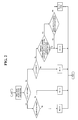
- Figure 3 is a flowchart illustrating a method for deciding the filter strength of a video coder based on a multilayer according to an embodiment of the present invention.
- the term 'video coder' is used as the common designation of a video encoder and a video decoder.
- the method according to the embodiment of the present invention, as illustrated in Figure 3 may additionally include S25, S30, S55 and S60 in comparison to the conventional method, as illustrated in Figure 2.
- target samples are selected around the boundary of a block (for example, a 4x4 pixel block).
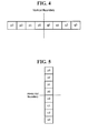
- the target samples means a set of samples arranged as shown in Figure 4 or Figure 5 around the boundary between the present block q and its neighboring block p.
- the upper block and the left block of the present block q correspond to the neighboring blocks p (P a and P b ), and thus the targets to which the deblocking filter is applied are the upper boundary and the left boundary of the present block q.
- the lower boundary and the right boundary of the present block q are filtered during the next process for the lower block and the right block of the present block.
- 4x4 blocks are exemplified since the 4x4 DCT transform is used in the H.264 standard and the minimum size of a variable block in motion prediction is 4x4 pixels.
- the filtering can also be applied to the block boundaries of 8x8 blocks and other block sizes.
- target samples appear around the left boundary of the present block q in the case where the block boundary is vertical.
- the target samples include four samples p0, p1, p2 and p3 on the left side of the vertical boundary line, which exist in the neighboring block p, and four samples q0, q1, q2 and q3 on the right side of the boundary line, which exist in the present block q.
- the number of reference samples and the number of filtered samples may be change according to the decided filter strength.
- target samples appear around the upper boundary of the present block q in the case where the block boundary is horizontal.
- the target samples include four samples p0, p1, p2 and p3 existing in the upper half of the horizontal boundary line (neighboring block p), and four samples q0, q1, q2 and q3 existing in the lower half of the horizontal boundary line (present block q).
- the deblocking filter is applied to the luminance signal component and the chrominance signal component, respectively, and the filtering is successively performed in a raster scan order on a unit of a macroblock that constitutes one frame.
- the filtering in the horizontal direction may be performed after the filtering in the vertical direction (as shown in Figure 4) is performed, and vice versa.
- intra coding may include both a coding according to a directional intra-prediction mode for predicting the present block from a certain part of a neighboring block of a frame, and coding according to an "intra BL mode" for predicting the present macroblock from an image restored from the lower layer of the present layer.
- block p and/or block q are intra-coded as a result of the decision of S15, it is then judged whether the block boundary coincides with the macroblock boundary S20. Since the block effect of the macroblock boundary appears higher than that of the 4x4 block boundary, the filter strength may be increased due to a decision in S20.
- Block boundary coincides with the macroblock boundary as a result of the decision of S20, it is judged whether block p and block q are in the intra BL mode S25. If so, the value that indicates the filter strength (hereinafter referred to as "Bs") may be set to 'A' S30; if not, Bs may be set to '4' S50. In one embodiment of the present invention, Bs may be set to '4' if even one of block p and block q is not in the BL mode.
- the value 'A' should be smaller than the value selected if the answer in S25 is 'No', that is, ⁇ 4'. This is because since the deblocking filter has already been applied to the image of the base layer that is provided to use the intra BL mode, it is unreasonable to apply to the image the filter having the same strength as other intra prediction modes. Accordingly, although 'A' may be 0, 1, 2, or 3, it has been confirmed by experiments that it is preferable that 'A' be '1'.
- Bs may be set to 'B' S60; if not, Bs may be set to '3' S65.
- Bs should be smaller than the value selected if the answer in S55 is 'No', that is, '3'. Accordingly, although 'B' may be 0, 1, or 2, it has been confirmed by experiments that it is preferable that 'B' be '1' .
- block p or block q has been intra-coded in S15
- block p or block q has been coded S70.
- blocks that are not intra-coded are inter-coded through inter prediction.
- the technique that does not code the difference is used, and thus the judgment of S70 is required. This is because the possibility that the block effect has occurred is low in comparison to the case where the blocks are coded, and thus, it is preferable to apply a relatively low filter strength in this case.
- Bs is set to '1' S85; if not, Bs is set to '0' S95.
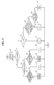
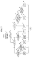
- Figure 7 is a flowchart illustrating a method of a video coder based on a multilayer for deciding the filter strength according to another embodiment of the present invention.
- the embodiment of Figure 3 it is judged in S25 whether both block p and block q are in the intra BL mode
- in the embodiment of Figure 7 it is judged whether either of block p or block q is in the intra BL mode in addition to whether both block p and block q are in the intra BL mode so as to apply different filter strengths to the cases, respectively.
- Bs may be set to 'A' as in the embodiment of Figure 3 S30. However, if only one of block p and block q is in the intra BL mode (which corresponds to 'Yes' in S35), Bs may be set to a new value 'C' S45. Meanwhile, if either block p or block q is not in the intra BL mode (which corresponds to 'No' in S35), Bs may be set to '4' in the same manner as in the embodiment of Figure 3 S50.
- the filter strength should be set to a value that is larger than 'A' but is smaller than '4'. If 'A' is set to '1' as in Figure 3, then 'C' should have a value of '2' or '3'.
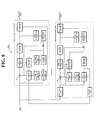
- Figure 8 is a block diagram illustrating the construction of a video encoder based on a multilayer that includes a deblocking filter according to the method for deciding the filter strength.
- the video encoder based on a multilayer may be implemented as a closed-loop type or an open-loop type.
- the closed-loop type video encoder performs a prediction with reference to the original frame
- the open-loop type video encoder performs a prediction with reference to a restored frame.
- a selection unit 280 selects and outputs one of a signal transferred from an up sampler 195 of a base-layer encoder 100, a signal transferred from a motion compensation unit 260 and a signal transferred from an intra prediction unit 270. This selection is performed by selecting from an intra BL mode, an inter prediction mode and an intra prediction mode, that has the highest coding efficiency.
- An intra prediction unit 270 predicts an image of the present block from an image of a restored neighboring block provided from an adder 215 according to a specified intra prediction mode.
- H.264 defines such an intra prediction mode, which includes eight modes having directions and one DC mode. Selection of one mode among them is performed by selecting the mode that has the highest coding efficiency.
- the intra prediction unit 270 provides predicted blocks generated according to the selected intra prediction mode to an adder 205.
- a motion estimation unit 250 performs motion estimation on the present macroblock of input video frames based on the reference frame and obtains motion vectors.
- An algorithm that is widely used for the motion estimation is a block matching algorithm. This block matching algorithm estimates a vector that has the minimum error in a specified search area of the reference frame as a motion vector.
- the motion estimation may be performed using a motion block of a fixed size or using a motion block having a variable size according to the hierarchical variable size block matching (HVSBM) algorithm.
- the motion estimation unit 250 provides motion data such as the motion vectors obtained as a result of motion estimation, the mode of the motion block, the reference frame number, and others, to an entropy coding unit 240.
- a motion compensation unit 260 performs motion compensation using the motion vector calculated by the motion estimation unit 250 and the reference frame and generates an inter-predicted image for the present frame.
- a subtracter 205 generates a residual frame by subtracting a signal selected by the selection unit 280 from the present input frame signal.
- a spatial transform unit 220 performs a spatial transform of the residual frame generated by the subtracter 205.
- DCT Discrete Cosine Transform
- wavelet transform and others may be used as the spatial transform method. Transform coefficients are obtained as a result of spatial transform. In the case of using the DCT as the spatial transform method, DCT coefficients are obtained, and in the case of using the wavelet transform method, wavelet coefficients are obtained.
- a quantization unit 230 generates quantization coefficients by quantizing the transform coefficients obtained by the spatial transform unit 220.
- the quantization means representing the transform coefficients expressed as real values by discrete values by dividing the transform values at predetermined intervals.
- Such a quantization method may be a scalar quantization, vector quantization, or others.
- the scalar quantization method is performed by dividing the transform coefficients by corresponding values from a quantization table and rounding the resultant values off to the nearest whole number.
- an embedded quantization method is mainly used as the quantization method.
- This embedded quantization method performs an efficient quantization using the spatial redundancy by preferentially coding components of the transform coefficients that exceed a threshold value by changing the threshold value (to 1/2).
- the embedded quantization method may be the Embedded Zerotrees Wavelet Algorithm (EZW), Set Partitioning in Hierarchical Trees (SPIHT), or Embedded ZeroBlock Coding (EZBC).
- the coding process before the entropy coding as described above is called lossy coding.
- the entropy coding unit 240 performs a lossless coding of the quantization coefficients and motion information provided by the motion estimation unit 250 and generates an output bit stream. Arithmetic coding or variable length coding may be used as the lossless coding method.
- Figure 9 is a view illustrating an example of the structure of a bit stream 50 generated according to an embodiment of the present invention.
- the bit stream is coded in the unit of a slice.
- the bit stream 50 includes a slice header 60 and slice data 70, and the slice data 70 is composed of a plurality of macroblocks (MBs) 71 to 74.
- Macroblock data for example, macroblock 73, are composed of an mb_type field 80, an mb_pred field 85 and a texture data field 90.
- mb_type field 80 a value indicating the kind of macroblock is recorded. That is, this field indicates whether the present macroblock is an intra macroblock, inter macroblock or intra BL macroblock.
- a detailed prediction mode according to the kind of the macroblock is recorded.
- the selected intra prediction mode is recorded, and in the case of the inter macroblock, a reference frame number and a motion vector by macroblock partitions are recorded.
- the coded residual frame i.e., texture data
- the coded residual frame i.e., texture data
- an enhanced-layer encoder 2 further includes an inverse quantization unit 271, an inverse DCT transform unit 272 and an adder 215, which are used to restore the lossy-coded frame by inversely decoding it.
- the inverse quantization unit 271 inversely quantizes the coefficients quantized by the quantization unit 230. This inverse quantization process is the inverse process of the quantization process.
- the inverse spatial transform unit 272 performs an inverse transform of the quantized results and provides the inversely-transformed results to the adder 215.
- the adder 215 restores the video frame by adding a signal provided from the inverse spatial transform unit 272 to a predicted signal selected by the selection unit 280 and stored in a frame buffer (not illustrated).
- the video frame restored by the adder 215 is provided to a deblocking filter 290, and the image of the neighboring block of the restored video frame is provided to the intra prediction unit 270.
- a filter strength decision unit 291 decides the filter strength with respect to the macroblock boundary and the block (for example, a 4x4 block) boundaries in one macroblock according to the filter strength decision method as explained with reference to Figure 3 and Figure 7.
- the macroblock has a size of 16x16 pixels, as illustrated in Figure 10
- the macroblock has a size of 8x8 pixels, as illustrated in Figure 11.
- 'Bs' is marked on the boundary of blocks that belong to a macroblock. However, 'Bs' is not marked on the right boundary line and the lower boundary line of the macroblock.
- the deblocking filter for the corresponding part is unnecessary, while if a macroblock exists to the right or below the present macroblock, the filter strength of the boundary lines is decided during the deblocking filtering process of the corresponding macroblock.
- FIG. 12 An example of the filter strength decision with respect to several boundary lines of a luminance-component macroblock as illustrated in Figure 10 is illustrated in Figure 12.
- the present macroblock and the left macroblock are intra BL macroblocks and the upper macroblock is an inter macroblock (or intra macroblock).
- the filter strength of all the 4x4 block boundary lines in the macroblock may be set to 'B', and the filter strength of the boundary lines (i.e., the left boundary line of the present macroblock) between the present macroblock and the left intra macroblock may be set to 'A'. Also, the filter strength of the upper boundary of the present macroblock may be set to ⁇ 4' .
- the filter strength of all the upper boundary lines of the present macroblock may be set to 'C', unlike the filter strength marked in Figure 12.
- the deblocking filter 290 actually performs the deblocking filtering with respect to the respective boundary lines according to the filter strength decided by the filter strength decision unit 291.
- the filtering operation can affect three pixels on each side of the boundary, i.e., ⁇ p2, p1, p0, q0, q1, q2 ⁇ , at maximum. This is decided with consideration to the filter strength Bs, quantization parameter QP of the neighboring block, and other parameters.
- ⁇ and ⁇ are threshold values determined according to the quantization parameter, FilterOffsetA, FilterOffsetB, and others.
- a 3-tab filter, a 4-tab filter or a 5-tab filter is applied to the inputs and P0, P1 and P2 (which are the results of filtering p0, p1, p2) and Q0, Q1 and Q2 (which are the results of filtering q0, q1, q2) can be outputted based on the threshold values ⁇ and ⁇ and eight actual pixels.
- a resultant frame D1 filtered by the deblocking filter 290 is provided to the motion estimation unit 250 to be used for the inter prediction of other input frames. Also, if an enhanced layer above the present enhanced layer exists, the frame D1 may be provided as a reference frame when the prediction of the intra BL mode is performed on the upper enhanced layer.
- the output D1 of the deblocking filter is inputted to the motion estimation unit 250 only in the case of the closed-loop type video encoder.
- the open-loop type video encoder such as a video encoder based on MCTF (Motion Compensated Temporal Filtering)
- the original frame is used as the reference frame during the inter prediction, and thus it is not required that the output of the deblocking filter be inputted to the motion estimation unit 250 again.
- the base-layer encoder 100 may include a spatial transform unit 120, a quantization unit 130, an entropy coding unit 140, a motion estimation unit 150, a motion compensation unit 160, an intra prediction unit 170, a selection unit 180, an inverse quantization unit 171, an inverse spatial transform unit 172, a down sampler 105, an up sampler and a deblocking filter 190.
- the down sampler 105 performs a down sampling of the original input frame to the resolution of the base layer, and the up sampler 195 performs an up sampling of the filtered output of the deblocking filter 190 and provides the up-sampled result to the selection unit 280 of the enhanced layer.
- the selection unit 180 selects one of the intra-predicted signal and the inter-predicted signal, and the deblocking filter 190 decides the filter strength in the same manner as in the conventional H.264.
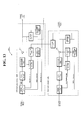
- FIG. 13 is a block diagram illustrating the construction of a video decoder 3000 according to an embodiment of the present invention.
- the video decoder 3000 includes an enhanced-layer decoder 600 and a base-layer decoder 500.
- An entropy decoding unit 610 performs a lossless decoding of the input enhanced-layer bit stream, in contrast to the entropy coding unit, and extracts macroblock type information (i.e., information that indicates the kind of the macroblock), intra prediction mode, motion information, texture data, and other information.
- macroblock type information i.e., information that indicates the kind of the macroblock
- the bit stream may be constructed as the example illustrated in FIG. 9.
- the kind of the macroblock is known from the mb_type field 80; the detailed intra prediction mode and motion information is known from the mb_pred field 85; and the texture data is known by reading the texture data field 90.
- the entropy decoding unit 610 provides the texture data to an inverse quantization unit 620, the intra prediction mode to an intra prediction unit 640 and motion information to a motion compensation unit 650. Also, the entropy decoding unit 610 provides the type of information of the present macroblock to a filter strength decision unit 691.
- the inverse quantization unit 620 inversely quantizes the texture information transferred from the entropy decoding unit 610. At this time, the same quantization table as that used in the video encoder side is used.
- an inverse spatial transform unit 630 performs an inverse spatial transform on the result of inverse quantization.
- This inverse spatial transform corresponds to the spatial transform performed in the video encoder. That is, if the DCT transform is performed in the encoder, an inverse DCT is performed in the video decoder, and if the wavelet transform is performed in the video encoder, an inverse wavelet transform is performed in the video decoder. As a result of inverse spatial transform, the residual frame is restored.
- the intra prediction unit 640 generates a predicted block for the present intra block from the restored neighboring intra block outputted from an adder 615 according to the intra prediction mode transferred from the entropy decoding unit 610 to provide the generated predicted block to the selection unit 660.
- the motion compensation unit 650 performs motion compensation using the motion information provided from the entropy decoding unit 610 and the reference frame provided from a deblocking filter 690.
- the predicted frame, generated as a result of motion compensation, is provided to the selection unit 660.
- the selection unit 660 selects one among a signal transferred from an up sampler 590, a signal transferred from the motion compensation unit 650 and a signal transferred from the intra prediction unit 640 and transfers the selected signal to the adder 615. At this time, the selection unit 660 discerns the type information of the present macroblock provided from the entropy decoding unit 610 and selects the corresponding signal among the three kinds of signals according to the type of the present macroblock.
- the adder 615 adds the signal outputted from the inverse spatial transform unit 630 to the signal selected by the selection unit 660 to restore the video frame of the enhanced layer.
- the filter strength decision unit 691 decides the filter strength with respect to the macroblock boundary and the block boundaries in one macroblock according to the filter strength decision method as explained with reference to Figure 3 and Figure 7.
- the type of macroblock as illustrated in Figure 12, should be known, and the information about the type of macroblock is provided from the entropy decoding unit 610.
- the resultant frame D3 filtered by the deblocking filter 690, as described above, is provided to the motion compensation unit 650 to generate an inter prediction frame for other input frames. Also, if an enhanced layer above the present enhanced layer exists, the frame D3 may be provided as the reference frame when the prediction of the intra BL mode is performed for the upper enhanced layer.
- the construction of the base-layer decoder 500 is similar to that of the enhanced-layer decoder. However, since the base-layer decoder 500 cannot use information of a lower layer, a selection unit 560 selects one of the intra-predicted signal and the inter-predicted signal, and the deblocking filter 590 decides the filter strength in the same manner as in the conventional H.264 algorithm. Also, an up sampler 595 performs an up sampling of the result filtered by the deblocking filter 590 and provides the up-sampled signal to the selection unit 660 of the enhanced layer.
- the video encoder or the video decoder includes two layers, i.e., a base layer and an enhanced layer.
- a base layer i.e., a base layer
- an enhanced layer i.e., a base layer
- the respective constituent elements of Figures 8 and 13 refer to software or hardware such as a FPGA (Field Programmable Gate Array) or an ASIC (Application Specific Integrated Circuit).
- the respective constituent elements may be constructed to reside in an addressable storage medium or to execute one or more processors. Functions provided in the respective constituent elements may be separated into further detailed constituent elements or combined into one constituent element, all of which perform specified functions.
- Figures 14a to 16b illustrate experimental results of embodiments of the present invention as compared with the prior art.
- an SVM 3.0 model of "ISO/IEC 21000 Scalable Video Coding, N6716, Palma, Oct. 2004" was used as the prior art.
- Figure 14a is a graph illustrating the luminance component PSNR (i.e., Y-PSNR) according to a variation of the bit rate in a crew sequence
- Figure 14b is a graph illustrating the luminance component PSNR (i.e., Y-PSNR) according to a variation of the bit rate in a harbour sequence.
- the picture quality is clearly improved by about 0.1 to 0.2 dB.
- the harbour sequence the picture quality improvement is insignificant.
- the method according to embodiments of the present invention has a great effect on rapid motion sequences, but has a relatively little effect on slow motion sequences or those having a strong temporal correlation. It is believed that this is because embodiments of the present invention improves the performance in the case of using the intra BL macroblock, but the number of intra BL macroblocks is small in the case of the slow motion sequences or those having strong temporal correlations.
- Figures 15a and 15b are graphs illustrating the performance improvement of embodiments of the present invention over the prior art with respect to a football sequence of CIF@1024kbps and with respect to a crew sequence of 4CIF@3000kbps.
- the average PSNR improvement is not great, but it is confirmed that the PSNR value is improved by up to 0.7dB in some frames. Also, in the crew sequence, it is confirmed that the PSNR value of several frames is improved by up to 0.17dB.
- the picture quality is greatly improved in the frames having rapid motion, while according to the prior art, the picture quality severely deteriorates in the frames having rapid motion.
- Figures 16a and 16b are views illustrating one frame of a football sequence restored by the prior art and one frame of Figure 16a restored according to embodiments of the present invention, respectively.
- the football sequence of CIF@1024kbps is used.
- the method according to embodiments of the present invention reduces an over-smoothing effect that is generated during the deblocking process, and thus, can preserve the visual details well in comparison to the method in the prior art.
- the deblocking filter strength can be properly set according to whether a certain block, to which the deblocking filter will be applied, is an intra BL mode block, in the multilayer video encoder/decoder.
- the picture quality of the restored video can be improved.
Landscapes
- Engineering & Computer Science (AREA)
- Multimedia (AREA)
- Signal Processing (AREA)
- Compression Or Coding Systems Of Tv Signals (AREA)
Applications Claiming Priority (2)
| Application Number | Priority Date | Filing Date | Title |
|---|---|---|---|
| US64100405P | 2005-01-04 | 2005-01-04 | |
| KR1020050008136A KR100679035B1 (ko) | 2005-01-04 | 2005-01-28 | 인트라 bl 모드를 고려한 디블록 필터링 방법, 및 상기방법을 이용하는 다 계층 비디오 인코더/디코더 |
Publications (2)
| Publication Number | Publication Date |
|---|---|
| EP1677545A2 true EP1677545A2 (de) | 2006-07-05 |
| EP1677545A3 EP1677545A3 (de) | 2016-01-13 |
Family
ID=36292673
Family Applications (1)
| Application Number | Title | Priority Date | Filing Date |
|---|---|---|---|
| EP06250002.0A Withdrawn EP1677545A3 (de) | 2005-01-04 | 2006-01-03 | Methode zur Steuerung des Deblockings und entsprechende Multilayercodierung |
Country Status (5)
| Country | Link |
|---|---|
| EP (1) | EP1677545A3 (de) |
| JP (4) | JP4191729B2 (de) |
| AU (1) | AU2005323586B2 (de) |
| CA (1) | CA2592515C (de) |
| WO (1) | WO2006073241A1 (de) |
Cited By (8)
| Publication number | Priority date | Publication date | Assignee | Title |
|---|---|---|---|---|
| WO2009051690A1 (en) * | 2007-10-16 | 2009-04-23 | Thomson Licensing | Methods and apparatus for artifact removal for bit depth scalability |
| WO2009126299A1 (en) * | 2008-04-11 | 2009-10-15 | Thomson Licensing | Deblocking filtering for displaced intra prediction and template matching |
| EP2265026A1 (de) * | 2009-06-16 | 2010-12-22 | Canon Kabushiki Kaisha | Verfahren und Vorrichtung zur Ensperrung des Filters von SVC-Videostreams während der Decodierung |
| EP2084906A4 (de) * | 2006-11-22 | 2011-06-22 | Samsung Electronics Co Ltd | Entblockierungs-filtervorrichtung und verfahren |
| CN101578874B (zh) * | 2007-01-04 | 2011-12-07 | 汤姆森特许公司 | 用于减少多视图编码视频中的照度补偿和/或色彩补偿的编码伪像的方法和装置 |
| WO2012096730A1 (en) * | 2011-01-10 | 2012-07-19 | Qualcomm Incorporated | Identification of samples in a transition zone |
| US9743081B2 (en) | 2009-07-07 | 2017-08-22 | Thomson Licensing | Methods and apparatus for collaborative partition coding for region based filters |
| WO2021036980A1 (en) * | 2019-08-23 | 2021-03-04 | Beijing Bytedance Network Technology Co., Ltd. | Using boundary strength in deblocking filtering |
Families Citing this family (16)
| Publication number | Priority date | Publication date | Assignee | Title |
|---|---|---|---|---|
| US7929610B2 (en) | 2001-03-26 | 2011-04-19 | Sharp Kabushiki Kaisha | Methods and systems for reducing blocking artifacts with reduced complexity for spatially-scalable video coding |
| US6931063B2 (en) | 2001-03-26 | 2005-08-16 | Sharp Laboratories Of America, Inc. | Method and apparatus for controlling loop filtering or post filtering in block based motion compensationed video coding |
| US7450641B2 (en) | 2001-09-14 | 2008-11-11 | Sharp Laboratories Of America, Inc. | Adaptive filtering based upon boundary strength |
| KR100679035B1 (ko) | 2005-01-04 | 2007-02-06 | 삼성전자주식회사 | 인트라 bl 모드를 고려한 디블록 필터링 방법, 및 상기방법을 이용하는 다 계층 비디오 인코더/디코더 |
| US7961963B2 (en) * | 2005-03-18 | 2011-06-14 | Sharp Laboratories Of America, Inc. | Methods and systems for extended spatial scalability with picture-level adaptation |
| KR100678958B1 (ko) * | 2005-07-29 | 2007-02-06 | 삼성전자주식회사 | 인트라 bl 모드를 고려한 디블록 필터링 방법, 및 상기방법을 이용하는 다 계층 비디오 인코더/디코더 |
| US8457201B2 (en) | 2006-01-09 | 2013-06-04 | Lg Electronics Inc. | Inter-layer prediction method for video signal |
| JP5529537B2 (ja) * | 2006-09-22 | 2014-06-25 | トムソン ライセンシング | 複数経路ビデオ符号化及び復号化のための方法及び装置 |
| KR100922275B1 (ko) * | 2006-12-15 | 2009-10-15 | 경희대학교 산학협력단 | 경계 필터링 강도의 결정 방법 및 이를 이용한 디블록킹필터링 방법과 장치 |
| JP5026092B2 (ja) * | 2007-01-12 | 2012-09-12 | 三菱電機株式会社 | 動画像復号装置および動画像復号方法 |
| US8204129B2 (en) * | 2007-03-27 | 2012-06-19 | Freescale Semiconductor, Inc. | Simplified deblock filtering for reduced memory access and computational complexity |
| JP5475409B2 (ja) * | 2009-11-20 | 2014-04-16 | 三菱電機株式会社 | 動画像符号化装置および動画像符号化方法 |
| CA2937202C (en) | 2010-12-17 | 2019-11-26 | Mitsubishi Electric Corporation | Image coding device, image decoding device, image coding method, and image decoding method |
| WO2014038330A1 (ja) * | 2012-09-06 | 2014-03-13 | ソニー株式会社 | 画像処理装置及び画像処理方法 |
| WO2015053111A1 (ja) * | 2013-10-11 | 2015-04-16 | ソニー株式会社 | 復号装置および復号方法、並びに、符号化装置および符号化方法 |
| US11582470B2 (en) * | 2020-09-03 | 2023-02-14 | Tencent America LLC | Method and apparatus for multi-scale neural image compression with intra-prediction residuals |
Family Cites Families (7)
| Publication number | Priority date | Publication date | Assignee | Title |
|---|---|---|---|---|
| US6160503A (en) * | 1992-02-19 | 2000-12-12 | 8×8, Inc. | Deblocking filter for encoder/decoder arrangement and method with divergence reduction |
| US6292512B1 (en) * | 1998-07-06 | 2001-09-18 | U.S. Philips Corporation | Scalable video coding system |
| US6931063B2 (en) * | 2001-03-26 | 2005-08-16 | Sharp Laboratories Of America, Inc. | Method and apparatus for controlling loop filtering or post filtering in block based motion compensationed video coding |
| CN1493157A (zh) * | 2001-09-12 | 2004-04-28 | ���µ�����ҵ��ʽ���� | 图像编码方法和图像解码方法 |
| US7203942B2 (en) * | 2001-09-25 | 2007-04-10 | Interuniversitair Microelektronica Centrum | Method for operating a real-time multimedia terminal in a QoS manner |
| WO2003103178A1 (en) * | 2002-05-29 | 2003-12-11 | Pixonics, Inc. | Video interpolation coding |
| MXPA04002265A (es) * | 2002-07-11 | 2004-06-29 | Matsushita Electric Ind Co Ltd | Metodo de determinacion de resistencia de filtracion, metodo de codificacion de pelicula y metodo de decodificacion de pelicula. |
-
2005
- 2005-12-22 JP JP2005369402A patent/JP4191729B2/ja not_active Expired - Fee Related
- 2005-12-27 CA CA2592515A patent/CA2592515C/en not_active Expired - Fee Related
- 2005-12-27 WO PCT/KR2005/004568 patent/WO2006073241A1/en not_active Ceased
- 2005-12-27 AU AU2005323586A patent/AU2005323586B2/en not_active Ceased
-
2006
- 2006-01-03 EP EP06250002.0A patent/EP1677545A3/de not_active Withdrawn
-
2007
- 2007-12-05 JP JP2007315275A patent/JP4191778B2/ja not_active Expired - Fee Related
- 2007-12-05 JP JP2007315274A patent/JP4191777B2/ja not_active Expired - Fee Related
- 2007-12-05 JP JP2007315276A patent/JP4191779B2/ja not_active Expired - Fee Related
Cited By (28)
| Publication number | Priority date | Publication date | Assignee | Title |
|---|---|---|---|---|
| EP2084906A4 (de) * | 2006-11-22 | 2011-06-22 | Samsung Electronics Co Ltd | Entblockierungs-filtervorrichtung und verfahren |
| US8345777B2 (en) | 2006-11-22 | 2013-01-01 | Samsung Electronics Co., Ltd. | Deblocking filtering apparatus and method |
| CN101578874B (zh) * | 2007-01-04 | 2011-12-07 | 汤姆森特许公司 | 用于减少多视图编码视频中的照度补偿和/或色彩补偿的编码伪像的方法和装置 |
| CN101828402B (zh) * | 2007-10-16 | 2013-09-11 | 汤姆森特许公司 | 用于比特深度可缩放性的伪像去除的方法和装置 |
| WO2009051690A1 (en) * | 2007-10-16 | 2009-04-23 | Thomson Licensing | Methods and apparatus for artifact removal for bit depth scalability |
| WO2009051704A1 (en) * | 2007-10-16 | 2009-04-23 | Thomson Licensing | Methods and apparatus for artifact removal for bit depth scalability |
| US8369422B2 (en) | 2007-10-16 | 2013-02-05 | Thomson Licensing | Methods and apparatus for artifact removal for bit depth scalability |
| US8391353B2 (en) | 2007-10-16 | 2013-03-05 | Thomson Licensing | Methods and apparatus for artifact removal for bit depth scalability |
| CN101828401B (zh) * | 2007-10-16 | 2013-07-17 | 汤姆森许可贸易公司 | 用于比特深度缩放的伪像去除的方法和设备 |
| TWI412283B (zh) * | 2007-10-16 | 2013-10-11 | Thomson Licensing | 用於編碼或解碼增強層之方法、裝置及非暫態電腦可讀式媒體 |
| KR20100132973A (ko) * | 2008-04-11 | 2010-12-20 | 톰슨 라이센싱 | 변위된 인트라 예측과 템플릿 매칭을 위한 디블록 필터링 |
| WO2009126299A1 (en) * | 2008-04-11 | 2009-10-15 | Thomson Licensing | Deblocking filtering for displaced intra prediction and template matching |
| KR20160052780A (ko) * | 2008-04-11 | 2016-05-12 | 톰슨 라이센싱 | 변위된 인트라 예측과 템플릿 매칭을 위한 디블록 필터링 |
| CN102090062B (zh) * | 2008-04-11 | 2013-12-11 | 汤姆森特许公司 | 用于位移帧内预测和模板匹配的去块滤波 |
| US9794597B2 (en) | 2008-04-11 | 2017-10-17 | Thomson Licensing Dtv | Methods and apparatus for deblocking filtering of non-local intra prediction |
| EP2265026A1 (de) * | 2009-06-16 | 2010-12-22 | Canon Kabushiki Kaisha | Verfahren und Vorrichtung zur Ensperrung des Filters von SVC-Videostreams während der Decodierung |
| US10708590B2 (en) | 2009-07-07 | 2020-07-07 | Interdigital Vc Holdings, Inc. | Methods and apparatus for collaborative partition coding for region based filters |
| US9743081B2 (en) | 2009-07-07 | 2017-08-22 | Thomson Licensing | Methods and apparatus for collaborative partition coding for region based filters |
| US11483556B2 (en) | 2009-07-07 | 2022-10-25 | Interdigital Vc Holdings, Inc. | Methods and apparatus for collaborative partition coding for region based filters |
| US11895296B2 (en) | 2009-07-07 | 2024-02-06 | Interdigital Vc Holdings, Inc. | Methods and apparatus for collaborative partition coding for region based filters |
| US12375654B2 (en) | 2009-07-07 | 2025-07-29 | Interdigital Vc Holdings, Inc. | Methods and apparatus for collaborative partition coding for region based filters |
| US9071851B2 (en) | 2011-01-10 | 2015-06-30 | Qualcomm Incorporated | Adaptively performing smoothing operations |
| US9807424B2 (en) | 2011-01-10 | 2017-10-31 | Qualcomm Incorporated | Adaptive selection of region size for identification of samples in a transition zone for overlapped block motion compensation |
| US10257543B2 (en) | 2011-01-10 | 2019-04-09 | Qualcomm Incorporated | Identification of samples in a transition zone |
| WO2012096730A1 (en) * | 2011-01-10 | 2012-07-19 | Qualcomm Incorporated | Identification of samples in a transition zone |
| WO2021036980A1 (en) * | 2019-08-23 | 2021-03-04 | Beijing Bytedance Network Technology Co., Ltd. | Using boundary strength in deblocking filtering |
| US11438585B2 (en) | 2019-08-23 | 2022-09-06 | Beijing Bytedance Network Technology Co., Ltd. | Deblocking filtering at coding block or subblock boundary |
| US12003714B2 (en) | 2019-08-23 | 2024-06-04 | Beijing Bytedance Network Technology Co., Ltd. | Deblocking filtering at coding block or subblock boundary |
Also Published As
| Publication number | Publication date |
|---|---|
| JP4191778B2 (ja) | 2008-12-03 |
| EP1677545A3 (de) | 2016-01-13 |
| JP2008104227A (ja) | 2008-05-01 |
| CA2592515A1 (en) | 2006-07-13 |
| JP4191777B2 (ja) | 2008-12-03 |
| JP4191779B2 (ja) | 2008-12-03 |
| JP4191729B2 (ja) | 2008-12-03 |
| WO2006073241A1 (en) | 2006-07-13 |
| JP2006191576A (ja) | 2006-07-20 |
| AU2005323586B2 (en) | 2009-10-22 |
| CA2592515C (en) | 2013-02-26 |
| JP2008104228A (ja) | 2008-05-01 |
| AU2005323586A1 (en) | 2006-07-13 |
| JP2008104226A (ja) | 2008-05-01 |
Similar Documents
| Publication | Publication Date | Title |
|---|---|---|
| US8542750B2 (en) | Deblocking control method considering intra BL mode and multilayer video encoder/decoder using the same | |
| JP4191779B2 (ja) | イントラblモードを考慮したビデオデコーディング方法、ビデオデコーダ、及び、記録媒体 | |
| KR100772883B1 (ko) | 인트라 bl 모드를 고려한 디블록 필터링 방법, 및 상기방법을 이용하는 다 계층 비디오 인코더/디코더 | |
| AU2006235923B2 (en) | Multilayer-based video encoding/decoding method and video encoder/decoder using smoothing prediction | |
| EP2008469B1 (de) | Verfahren zur videocodierung auf mehrschichtbasis und vorrichtung dafür | |
| AU2006289710B2 (en) | Deblocking filtering method considering intra-BL mode and multilayer video encoder/decoder using the same | |
| EP1817911A1 (de) | Verfahren und vorrichtung für mehrschichtige videokodierung und -dekodierung | |
| Akyol et al. | Motion-compensated temporal filtering within the H. 264/AVC standard |
Legal Events
| Date | Code | Title | Description |
|---|---|---|---|
| PUAI | Public reference made under article 153(3) epc to a published international application that has entered the european phase |
Free format text: ORIGINAL CODE: 0009012 |
|
| 17P | Request for examination filed |
Effective date: 20060121 |
|
| AK | Designated contracting states |
Kind code of ref document: A2 Designated state(s): AT BE BG CH CY CZ DE DK EE ES FI FR GB GR HU IE IS IT LI LT LU LV MC NL PL PT RO SE SI SK TR |
|
| AX | Request for extension of the european patent |
Extension state: AL BA HR MK YU |
|
| RAP1 | Party data changed (applicant data changed or rights of an application transferred) |
Owner name: SAMSUNG ELECTRONICS CO., LTD. |
|
| PUAL | Search report despatched |
Free format text: ORIGINAL CODE: 0009013 |
|
| AK | Designated contracting states |
Kind code of ref document: A3 Designated state(s): AT BE BG CH CY CZ DE DK EE ES FI FR GB GR HU IE IS IT LI LT LU LV MC NL PL PT RO SE SI SK TR |
|
| AX | Request for extension of the european patent |
Extension state: AL BA HR MK YU |
|
| RBV | Designated contracting states (corrected) |
Designated state(s): AT BE BG CH CY CZ DE DK EE ES FI FR GB GR HU IE IS IT LI LT LU LV MC NL PL PT RO SE SI SK TR |
|
| RBV | Designated contracting states (corrected) |
Designated state(s): AT BE BG CH CY CZ DE DK EE ES FI FR GB GR HU IE IS IT LI LT LU LV MC NL PL PT RO SE SI SK TR |
|
| AKX | Designation fees paid |
Designated state(s): AT BE BG CH CY CZ DE DK EE ES FI FR GB GR HU IE IS IT LI LT LU LV MC NL PL PT RO SE SI SK TR |
|
| AXX | Extension fees paid |
Extension state: HR Extension state: AL Extension state: MK Extension state: YU Extension state: BA |
|
| STAA | Information on the status of an ep patent application or granted ep patent |
Free format text: STATUS: THE APPLICATION HAS BEEN WITHDRAWN |
|
| 18W | Application withdrawn |
Effective date: 20161223 |