EP1677572A1 - Microphone imperméable à l'eau - Google Patents
Microphone imperméable à l'eau Download PDFInfo
- Publication number
- EP1677572A1 EP1677572A1 EP05257928A EP05257928A EP1677572A1 EP 1677572 A1 EP1677572 A1 EP 1677572A1 EP 05257928 A EP05257928 A EP 05257928A EP 05257928 A EP05257928 A EP 05257928A EP 1677572 A1 EP1677572 A1 EP 1677572A1
- Authority
- EP
- European Patent Office
- Prior art keywords
- gap
- diaphragm
- anterior
- chamber
- case
- Prior art date
- Legal status (The legal status is an assumption and is not a legal conclusion. Google has not performed a legal analysis and makes no representation as to the accuracy of the status listed.)
- Granted
Links
Images




Classifications
-
- H—ELECTRICITY
- H04—ELECTRIC COMMUNICATION TECHNIQUE
- H04R—LOUDSPEAKERS, MICROPHONES, GRAMOPHONE PICK-UPS OR LIKE ACOUSTIC ELECTROMECHANICAL TRANSDUCERS; ELECTRIC HEARING AIDS; PUBLIC ADDRESS SYSTEMS
- H04R1/00—Details of transducers, loudspeakers or microphones
- H04R1/08—Mouthpieces; Microphones; Attachments therefor
- H04R1/083—Special constructions of mouthpieces
- H04R1/086—Protective screens, e.g. all weather or wind screens
Definitions
- the present invention relates to a waterproof microphone (hereinbelow abbreviated to a waterproof mike) allowing sufficient sound collection over wider frequency bands in, for example, high-humidity places exposed to rain and fog, high mountains with low pressure and even under water with high pressure.
- a waterproof microphone hereinbelow abbreviated to a waterproof mike
- a condenser-type waterproof mike includes a cylinder-shaped case, a diaphragm and an electrode plate, where the cylinder-shaped case has an anterior wall, and the diaphragm and the electrode plate are disposed in the case in sequence from the anterior wall side toward the rear side.
- An anterior chamber is formed between the anterior wall and the diaphragm.
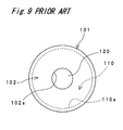
- the anterior wall 102 of the case 101 had an aperture 102a in the center.
- the aperture 102a was not overlapped with an inner face 110a of the anterior chamber 110 (see Patent No. 3486151).
- the conventional waterproof mike was structured such that the aperture 102a was not overlapped with the inner face 110a of the anterior chamber 110 as shown in Fig. 9, moisture such as rain water, if entering the anterior chamber 110, is not easily discharged out of the case 101 but remained in the anterior chamber 110.
- the moisture in the anterior chamber 110 is kept in contact with the diaphragm 120, which causes considerable attenuation of sound pressure collected by the diaphragm. As a result, sufficient sound collection is disadvantageously disturbed.
- An object of the present invention is to provide a waterproof mike allowing sufficient sound collection without being affected by moisture.
- the present invention provides a waterproof mike, comprising:
- the present invention moisture such as rain water, if entering the anterior chamber, is smoothly discharged out of the case from the discharge aperture along the inner face of the anterior chamber. As a result, it becomes possible to prevent the moisture from remaining on the first diaphragm and to prevent degradation of sound pressure collected by the first diaphragm. Moreover, the presence of the first diaphragm prevents the moisture in the anterior chamber from entering the first gap.
- first gap, the second gap and the posterior chamber are linked, and therefore when pressure in the anterior chamber changes, the pressures in the first gap, the second gap and the posterior chamber become equal in compliance with the change. This prevents the second diaphragm from sinking and staying in contact with the electrode plate, or from protruding and gaining an excessively increased gap with the electrode plate, and allows the second diaphragm to normally vibrate in response to voice so as to achieve sufficient sound collection over wider frequency bands.
- the electrode plate has a hole linking the second gap and the posterior chamber
- the second diaphragm has a throttle hole linking the first gap and the second gap
- the throttle hole does not substantially transmit dynamic pressure fluctuation in the first gap to the second gap but substantially transmits static pressure fluctuation in the first gap to the second gap.
- the pressure in the anterior chamber increases or decreases gradually, i.e., increases or decreases statically, from atmospheric pressure
- the pressure in the first gap increases or decreases statically in response to this increase or decrease, and this increase or decrease is substantially transmitted to the second gap through the throttle hole in the second diaphragm.
- the increase or decrease is transmitted to the posterior chamber through the hole in the electrode plate, so that the pressures in the first gap, the second gap and the posterior chamber become equal.
- the throttle hole in the second diaphragm does not substantially transmit dynamic pressure fluctuation in the first gap, which is caused by voices to be collected, to the second gap, so that the second diaphragm vibrates in response to voice. Therefore, it becomes possible to normally vibrate the second diaphragm in response to voice with simple structure.
- the electrode plate has a hole linking the second gap and the posterior chamber, a throttle pathway linking the first gap and the posterior chamber is formed outside lateral faces of the second diaphragm and the electrode plate, and the throttle pathway does not substantially transmit dynamic pressure fluctuation in the first gap to the posterior chamber but substantially transmits static pressure fluctuation in the first gap to the posterior chamber.
- the pressure in the anterior chamber increases or decreases gradually, i.e., increases or decreases statically, from atmospheric pressure
- the pressure in the first gap increases or decreases statically in response to this increase or decrease, and this increase or decrease is substantially transmitted to the posterior chamber through the throttle pathway.
- the increase or decrease is transmitted to the second gap through the hole in the electrode plate, so that the pressures in the first gap, the second gap and the posterior chamber become equal.
- the throttle pathway does not substantially transmit dynamic pressure fluctuation in the first gap, which is caused by voices to be collected, to the posterior chamber, so that the second diaphragm vibrates in response to voice. Therefore, it becomes possible to normally vibrate the second diaphragm in response to voice with simple structure.
- the waterproof mike further comprises a back plate disposed behind the electrode plate in the case, wherein the back plate has an air hole linking the posterior chamber and an outside of the case.
- the waterproof mike further comprises a polymeric film having air permeability disposed on a rear face of the back plate.
- the waterproof mike in one embodiment, when low frequencies are applied to the first diaphragm, resonance of the second diaphragm by vibration of the first diaphragm may be prevented.
- the anterior wall of the case has the discharge apertures overlapped with the inner face of the anterior chamber, which allows sufficient sound collection without being influenced by moisture.
- An anterior chamber 20 is formed between the anterior wall 2 and the first diaphragm 11.
- a first gap 21 is formed between the first diaphragm 11 and the second diaphragm 12.
- a second gap 22 is formed between the second diaphragm 12 and the electrode plate 13.
- a posterior chamber 23 is formed between the electrode plate 13 and the back plate 14.
- the first diaphragm 11 is made of metals such as aluminum, iron, stainless and copper or resins such as plastic.
- the first diaphragm 11 is mounted on the rear face of a first ring 31.
- the first ring 31 is retained in the case 1 by the anterior wall 2.
- the second diaphragm 12 is formed by evaporating metal on a synthetic resin plate and permanently charging its surface.
- the second diaphragm 12 is made of a so-called electret material having a permanently charged surface.
- the second diaphragm 12 is mounted on the rear face of a second ring 32.
- the second diaphragm 12 has a throttle hole 12a linking the first diaphragm 11 and the second diaphragm 12.
- the back plate 14 has an air hole 14a linking the posterior chamber 23 and the outside of the case 1.
- the back plate 14 is made of, for example, PCB (Poly Chlorinated Biphenyl).
- the back plate 14 is in contact with an axial rear end face of the insulator 17.
- a conversion module 19 is mounted on the front face of the back plate 14, while a plus output terminal 15 and a minus output terminal 16 are mounted on the rear face of the back plate 14.
- a conductive plate 18 is disposed between the electrode plate 13 and the back plate 14 and on the inner face of the insulator 17.
- a spacer 33 is disposed between the second diaphragm 12 and the insulator 17.
- the back plate 14 is retained in the case 1 by a circular holder 34.
- the holder 34 is bonded to the inner face of the case 1 with, for example, waterproof adhesives.
- the first ring 31 is also bonded to the inner face of the case 1 with, for example, waterproof adhesives.
- the first gap 21, the second gap 22 and the posterior chamber 23 are linked.
- the first gap 21 is sealed from the anterior chamber 20 by the first diaphragm 11. More particularly, the anterior chamber 20 and the first gap 21 are not linked to each other.
- the anterior wall 2 has a central aperture 2a and two discharge apertures 2b, 2b extending in two radial directions from the central aperture 2a.
- the central aperture 2a is in an almost circular shape while the discharge apertures 2b are in an almost rectangular shape. More particularly, these two discharge apertures 2b, 2b extend radially from the inner face of the central aperture 2a to the peripheral edge of the anterior wall 2.
- the discharge apertures 2b are overlapped with an inner face 20a of the anterior chamber 20. More particularly, the inner face 20a of the anterior chamber 20 corresponds to the inner face of the first ring 31.
- the throttle hole 12a of the second diaphragm 12 is so set as to have a diameter which does not substantially (purposefully) transmit dynamic pressure fluctuation in the first gap 21 (caused by voice and the like) to the second gap 22, but substantially transmit static pressure fluctuation in the first gap 21 (caused by gradual increase in altitude or water depth) to the second gap 22.
- the second diaphragm 12, the electrode plate 13 and the like constitute a sound pressure-electrical signal conversion section 4.
- the conversion module 19 equalizes an impedance in the sound pressure-electrical signal conversion section 4 caused by voice and the like to an impedance in an external output-side circuit.
- the conversion module 19 which has resistances R1 to R7, capacities C1 to C4, and tow-stage transistors Q1, Q2 constituting an emitter follower, amplifies weak electric signals inputted from the sound pressure-electrical signal conversion section 4 and equalizes a high impedance in the sound pressure-electrical signal conversion section 4 and a low impedance in signal lines and speakers connected to the output terminals 15, 16, so that an output impedance of the waterproof mike is reduced to not more than 100 Q. Consequently, it was confirmed that when the output signal line was prolonged to about 200m, voice signals could be transmitted sufficiently.
- the conversion module 19 employs two-line transmission method in which the plus output terminal 15 is used also as a power supply line to the sound pressure-electrical signal conversion section 4, which brings about an advantage that the structure is simplified compared to the three-line method.
- the thus-structured waterproof mike moisture such as rain water, if entering the anterior chamber 20, is smoothly discharged out of the case 1 from the discharge apertures 2b along the inner face 20a of the anterior chamber 20.
- moisture such as rain water
- the first diaphragm 11 prevents the moisture from remaining and sticking on the first diaphragm 11 and to prevent degradation of sound pressure collected by the first diaphragm 11 through the central aperture 2a and the discharge apertures 2b.
- the presence of the first diaphragm 11 prevents the moisture in the anterior chamber 20 from entering the first gap 21.
- first gap 21, the second gap 22 and the posterior chamber 23 are linked, and therefore when pressure in the anterior chamber 20 changes, the pressures in the first gap 21, the second gap 22 and the posterior chamber 23 become equal in compliance with the change. This prevents the second diaphragm 12 from sinking and staying in contact with the electrode plate 13, or from protruding and gaining an excessively increased gap with the electrode plate 13, and allows the second diaphragm to normally vibrate in response to voice so as to achieve sufficient sound collection over wider frequency bands.
- the pressure in the anterior chamber 20 increases gradually, i.e., increases statically, from atmospheric pressure
- the pressure in the first gap 21 increases statically in response to this increase, and compressed air is substantially transmitted to the second gap 22 through the throttle hole 12a in the second diaphragm 12 as shown by an arrow in Fig. 1B.
- the compressed air is transmitted to the posterior chamber 23 through the hole 13a in the electrode plate 13, so that the pressures in the first gap 21, the second gap 22 and the posterior chamber 23 become equal.
- the throttle hole 12a in the second diaphragm 12 does not substantially transmit dynamic pressure fluctuation in the first gap 11 and the first gap 21, which is caused by voices to be collected, to the second gap, so that the second diaphragm 12 vibrates in response to voice.
- the pressure in the anterior chamber 20 is decreased from atmospheric pressure, air flows in direction opposite to the arrow in Fig. 1B.
- the waterproof mike may be used for sound collection in highways, nuclear devices and in tunnels.
- the waterproof mike may also be employed as radio transceiver microphones and communication microphones during operation on ship decks.
- the pressure in the anterior chamber 20 changes, the pressure in the posterior chamber 23 and the pressure outside the case 1 become equal with the presence of the air hole 14a in the back plate 14. More particularly, the pressures in the anterior chamber 20, the first gap 21, the second gap 22 and the posterior chamber 23 become equal. Thus, when the pressure outside the case 1 changes, deformation of the first diaphragm 11 may be suppressed.
- the thickness of the first diaphragm 11 should preferably be equal to or smaller than the thickness of the second diaphragm 12, so that when low frequencies are applied to the first diaphragm 11, resonance of the second diaphragm 12 by vibration of the first diaphragm 11 may be prevented.
- first diaphragm 11 so as to be roundish and protrude forward or backward makes it possible to secure specified frequency regions, which allows obtention of good characteristics.
- a cover cloth for covering the front face of the anterior wall 2 may be placed to prevent dirt and the like from entering the anterior chamber 20.
- moisture entering the anterior chamber 20 may be smoothly discharged out of the case 1 from a plurality of the discharge apertures 2d through the inner face 20a of the anterior chamber 20, which allows more sufficient sound collection.
- the throttle pathway 10 includes gaps between the outer peripheral faces of the second ring 32, the second diaphragm 12, the spacer 33 and the electrode plate 13 and the inner face of the case 1.
- the insulator 17 and the electrode plate 18 are not in a circular shape but are, for example, columns having a circular arc cross section and are provided in a plurality of units. There are gaps between adjacent insulators 17. There are gaps between adjacent electrode plates 18.
- the pressure in the anterior chamber 20 increases gradually, i.e., increases statically, from atmospheric pressure
- the pressure in the first gap 21 increases statically in response to this increase, and compressed air is substantially transmitted to the posterior chamber 23 through the throttle pathway 10, gaps between the adjacent insulators 17, and gaps between the adjacent electrode plates 18 in this order as shown by an arrow in Fig. 3B.
- the compressed air is transmitted to the second gap 22 through the hole 13a on the electrode plate 13, so that the pressures in the first gap 21, the second gap 22 and the posterior chamber 23 become equal.
- the throttle pathway 10 does not substantially transmit dynamic pressure fluctuation in the first gap 11 and the first gap 21, which is caused by voice to be collected, to the posterior chamber 23, so that the second diaphragm 12 vibrates in response to voice. It is to be noted that when the pressure in the anterior chamber 20 is decreased from atmospheric pressure, air flows in direction opposite to the arrow in Fig. 3B.
- Fig. 4 shows a waterproof mike in a third embodiment of the present invention.
- the third embodiment is different from the first embodiment in the point that a polymeric film 40 is placed on the rear face of the back plate 14.
- the polymeric film 40 allows only air to be inducted into or discharged from the case 1.
- the back plate 14 is retained in the case 1 with a caulking portion 5 disposed in a rear aperture end of the case 1. This makes it possible to reduce the number of components.
- Fig. 5 shows a waterproof mike in a fourth embodiment of the present invention.
- the fourth embodiment of the present invention is different from the first embodiment in the point that the anterior wall 2 has a plurality of discharge apertures 2e juxtaposed at even intervals in radial direction.
- the discharge apertures 2e are in an almost rectangular shape extending sideways so as to cross the peripheral edge of the anterior wall 2.
- the anterior wall 2 does not have the central aperture 2a of the first embodiment.
- the discharge apertures 2e are overlapped with the inner face 20a of the anterior chamber 20.
- the anterior wall 2 (discharge apertures 2e) may be simply structured while reliable sound collection and water discharge may be achieved.
- Fig. 7 shows a waterproof mike in a sixth embodiment of the present invention.
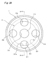
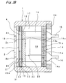
- the sixth embodiment of the present invention is different from the first embodiment in the point that the anterior wall 2 has a central aperture 2h and eight discharge apertures 2i extending in eight radial directions from the central aperture 2h.
- a plurality of the discharge apertures 2i are positioned at almost even intervals in circumferential direction.
- the central aperture 2h is in an almost circular shape, while the discharge apertures 2i are in an almost rectangular shape. More particularly, these eight discharge apertures 2i extend radially from the inner face of the central aperture 2h to the peripheral edge of the anterior wall 2.
- the discharge apertures 2i are overlapped with the inner face 20a of the anterior chamber 20.
- the throttle pathway 10 includes gaps between the outer peripheral faces of the second ring 32, the second diaphragm 12, the spacer 33 and the electrode plate 13 and the inner face of the inner case 51.
- the insulator 17 and the electrode plate 18 are not in a circular shape but are, for example, columns having a circular arc cross section and are provided in a plurality of units. There are gaps between adjacent insulators 17. There are gaps between adjacent electrode plates 18.
Landscapes
- Physics & Mathematics (AREA)
- Engineering & Computer Science (AREA)
- Acoustics & Sound (AREA)
- Signal Processing (AREA)
- Electrostatic, Electromagnetic, Magneto- Strictive, And Variable-Resistance Transducers (AREA)
- Details Of Audible-Bandwidth Transducers (AREA)
- Piezo-Electric Transducers For Audible Bands (AREA)
- Battery Mounting, Suspending (AREA)
Applications Claiming Priority (1)
| Application Number | Priority Date | Filing Date | Title |
|---|---|---|---|
| JP2004380295A JP3957714B2 (ja) | 2004-12-28 | 2004-12-28 | 防水マイク |
Publications (2)
| Publication Number | Publication Date |
|---|---|
| EP1677572A1 true EP1677572A1 (fr) | 2006-07-05 |
| EP1677572B1 EP1677572B1 (fr) | 2008-08-06 |
Family
ID=36035766
Family Applications (1)
| Application Number | Title | Priority Date | Filing Date |
|---|---|---|---|
| EP05257928A Expired - Lifetime EP1677572B1 (fr) | 2004-12-28 | 2005-12-21 | Microphone imperméable à l'eau |
Country Status (5)
| Country | Link |
|---|---|
| US (1) | US7991173B2 (fr) |
| EP (1) | EP1677572B1 (fr) |
| JP (1) | JP3957714B2 (fr) |
| CN (1) | CN1798454B (fr) |
| DE (1) | DE602005008698D1 (fr) |
Families Citing this family (20)
| Publication number | Priority date | Publication date | Assignee | Title |
|---|---|---|---|---|
| EP2037698B1 (fr) * | 2006-07-04 | 2014-09-10 | JVC KENWOOD Corporation | Dispositif de microphone |
| JP5088779B2 (ja) * | 2007-08-07 | 2012-12-05 | 日本ゴア株式会社 | 電気音響変換装置、電子機器、及び防水カバー、並びに、電気音響変換装置の通気試験方法 |
| JP4872105B2 (ja) * | 2007-12-21 | 2012-02-08 | Necカシオモバイルコミュニケーションズ株式会社 | 防水音響構造、及び電子機器 |
| EP2233897A1 (fr) * | 2008-01-18 | 2010-09-29 | Nittobo Acoustic Engineering Co., Ltd. | Appareil, systeme et procede d'identification et de mesure d'une source sonore |
| JP5258030B2 (ja) * | 2008-07-25 | 2013-08-07 | Necカシオモバイルコミュニケーションズ株式会社 | 防水音響構造、及び電子機器 |
| JP4456656B1 (ja) * | 2009-07-13 | 2010-04-28 | 成高 鈴木 | 防水マイクロフォン |
| CN102687489B (zh) * | 2009-10-15 | 2014-12-10 | 日本电气株式会社 | 电子装置 |
| JP5216033B2 (ja) * | 2010-02-09 | 2013-06-19 | Toa株式会社 | マイクロホン用カバーおよびこれを備えたマイクロホン |
| WO2011116246A1 (fr) | 2010-03-19 | 2011-09-22 | Advanced Bionics Ag | Enveloppes étanches pour éléments acoustiques et appareil comprenant une telle enveloppe |
| EP2666306B1 (fr) | 2011-01-18 | 2017-03-15 | Advanced Bionics AG | Modules externes résistants à l'humidité et systèmes de stimulation cochléaire implantables comprenant ce module externe |
| US8724841B2 (en) | 2012-08-30 | 2014-05-13 | Apple Inc. | Microphone with acoustic mesh to protect against sudden acoustic shock |
| JP6213871B2 (ja) * | 2012-12-27 | 2017-10-18 | パナソニックIpマネジメント株式会社 | 防水マイク装置 |
| WO2015056443A1 (fr) * | 2013-10-15 | 2015-04-23 | パナソニックIpマネジメント株式会社 | Microphone |
| US9769578B2 (en) | 2014-03-19 | 2017-09-19 | Cochlear Limited | Waterproof molded membrane for microphone |
| US9226076B2 (en) * | 2014-04-30 | 2015-12-29 | Apple Inc. | Evacuation of liquid from acoustic space |
| CN204761633U (zh) * | 2015-06-10 | 2015-11-11 | 瑞声光电科技(常州)有限公司 | 发声器件 |
| US10209123B2 (en) | 2016-08-24 | 2019-02-19 | Apple Inc. | Liquid detection for an acoustic module |
| DE102016116424B4 (de) | 2016-09-02 | 2026-02-05 | Sennheiser Electronic Se & Co. Kg | Mikrofoneinheit für eine Actionkamera |
| JP7441132B2 (ja) * | 2020-07-16 | 2024-02-29 | ホシデン株式会社 | 防水マイクロホン |
| CN112068225A (zh) * | 2020-09-16 | 2020-12-11 | 东方智感(浙江)科技股份有限公司 | 一种电子式降雨量测量装置及方法 |
Citations (2)
| Publication number | Priority date | Publication date | Assignee | Title |
|---|---|---|---|---|
| US3064089A (en) * | 1960-06-24 | 1962-11-13 | Donald P Ward | Waterproof inertial type microphone |
| JP2001313990A (ja) * | 2000-04-28 | 2001-11-09 | Uetax Corp | 防水マイク |
Family Cites Families (6)
| Publication number | Priority date | Publication date | Assignee | Title |
|---|---|---|---|---|
| US3909529A (en) * | 1971-12-27 | 1975-09-30 | Us Navy | Immersible diver{3 s microphone |
| DK146770C (da) * | 1981-11-13 | 1984-06-04 | Brueel & Kjaer As | Kapacitiv transducer |
| DE19715365C2 (de) * | 1997-04-11 | 1999-03-25 | Sennheiser Electronic | Kondensatormikrofon |
| US6512834B1 (en) * | 1999-07-07 | 2003-01-28 | Gore Enterprise Holdings, Inc. | Acoustic protective cover assembly |
| CN1162759C (zh) * | 2000-03-02 | 2004-08-18 | 阿苏拉布股份有限公司 | 在一电话手表中装入一麦克风和一压力补偿元件的装置 |
| DE10317264B3 (de) * | 2003-04-14 | 2005-02-10 | Sennheiser Electronic Gmbh & Co. Kg | Mikrofon |
-
2004
- 2004-12-28 JP JP2004380295A patent/JP3957714B2/ja not_active Expired - Lifetime
-
2005
- 2005-04-15 CN CN2005100659236A patent/CN1798454B/zh not_active Expired - Lifetime
- 2005-12-21 EP EP05257928A patent/EP1677572B1/fr not_active Expired - Lifetime
- 2005-12-21 DE DE602005008698T patent/DE602005008698D1/de not_active Expired - Lifetime
- 2005-12-27 US US11/317,305 patent/US7991173B2/en active Active
Patent Citations (2)
| Publication number | Priority date | Publication date | Assignee | Title |
|---|---|---|---|---|
| US3064089A (en) * | 1960-06-24 | 1962-11-13 | Donald P Ward | Waterproof inertial type microphone |
| JP2001313990A (ja) * | 2000-04-28 | 2001-11-09 | Uetax Corp | 防水マイク |
Non-Patent Citations (1)
| Title |
|---|
| PATENT ABSTRACTS OF JAPAN vol. 2002, no. 03 3 April 2002 (2002-04-03) * |
Also Published As
| Publication number | Publication date |
|---|---|
| DE602005008698D1 (de) | 2008-09-18 |
| JP2006186848A (ja) | 2006-07-13 |
| CN1798454A (zh) | 2006-07-05 |
| JP3957714B2 (ja) | 2007-08-15 |
| US7991173B2 (en) | 2011-08-02 |
| US20060140432A1 (en) | 2006-06-29 |
| EP1677572B1 (fr) | 2008-08-06 |
| CN1798454B (zh) | 2012-07-25 |
Similar Documents
| Publication | Publication Date | Title |
|---|---|---|
| US7991173B2 (en) | Waterproof microphone | |
| US8824713B2 (en) | Microphone for a hearing aid | |
| US7292696B2 (en) | Electret capacitor microphone | |
| EP1397023A2 (fr) | Microphone avec un conduit d'admission de son amélioré | |
| US20020154790A1 (en) | Cylindrical microphone having an electret assembly in the end cover | |
| US7873176B2 (en) | Electrostatic microphone | |
| JP2005057775A (ja) | エレクトレットコンデンサーマイクロホン | |
| US6594155B2 (en) | Mounting structure of electronic parts | |
| KR100427698B1 (ko) | 지향성 콘덴서 마이크로폰 | |
| US8509459B1 (en) | Noise cancelling microphone with reduced acoustic leakage | |
| KR102172832B1 (ko) | 무선 이어폰 | |
| US20170188159A1 (en) | Microphone | |
| CN210694279U (zh) | 双向调节指向性咪头 | |
| KR100437681B1 (ko) | 지향성 마이크로폰 | |
| JP2006166151A (ja) | ステレオ用スピーカ | |
| US20250220367A1 (en) | Ear-worn hearing device with electrical cable assembly or sound tube | |
| KR200220630Y1 (ko) | 콘덴서 마이크로 폰 | |
| CN218734957U (zh) | 麦克风及电子设备 | |
| EP4270995A1 (fr) | Dispositif auditif avec microphone suspendu | |
| JP2003087898A (ja) | コンデンサマイクロホン | |
| KR200289305Y1 (ko) | 지향성 마이크로폰 | |
| JPH037302B2 (fr) | ||
| IE55102B1 (en) | Electro-acoustic transducer |
Legal Events
| Date | Code | Title | Description |
|---|---|---|---|
| PUAI | Public reference made under article 153(3) epc to a published international application that has entered the european phase |
Free format text: ORIGINAL CODE: 0009012 |
|
| AK | Designated contracting states |
Kind code of ref document: A1 Designated state(s): AT BE BG CH CY CZ DE DK EE ES FI FR GB GR HU IE IS IT LI LT LU LV MC NL PL PT RO SE SI SK TR |
|
| AX | Request for extension of the european patent |
Extension state: AL BA HR MK YU |
|
| 17P | Request for examination filed |
Effective date: 20061019 |
|
| 17Q | First examination report despatched |
Effective date: 20061115 |
|
| AKX | Designation fees paid |
Designated state(s): CH DE DK FR GB IT LI |
|
| GRAP | Despatch of communication of intention to grant a patent |
Free format text: ORIGINAL CODE: EPIDOSNIGR1 |
|
| GRAS | Grant fee paid |
Free format text: ORIGINAL CODE: EPIDOSNIGR3 |
|
| GRAA | (expected) grant |
Free format text: ORIGINAL CODE: 0009210 |
|
| AK | Designated contracting states |
Kind code of ref document: B1 Designated state(s): CH DE DK FR GB IT LI |
|
| REG | Reference to a national code |
Ref country code: GB Ref legal event code: FG4D |
|
| REG | Reference to a national code |
Ref country code: CH Ref legal event code: EP |
|
| REF | Corresponds to: |
Ref document number: 602005008698 Country of ref document: DE Date of ref document: 20080918 Kind code of ref document: P |
|
| PG25 | Lapsed in a contracting state [announced via postgrant information from national office to epo] |
Ref country code: DK Free format text: LAPSE BECAUSE OF FAILURE TO SUBMIT A TRANSLATION OF THE DESCRIPTION OR TO PAY THE FEE WITHIN THE PRESCRIBED TIME-LIMIT Effective date: 20080806 |
|
| PLBE | No opposition filed within time limit |
Free format text: ORIGINAL CODE: 0009261 |
|
| STAA | Information on the status of an ep patent application or granted ep patent |
Free format text: STATUS: NO OPPOSITION FILED WITHIN TIME LIMIT |
|
| 26N | No opposition filed |
Effective date: 20090507 |
|
| REG | Reference to a national code |
Ref country code: CH Ref legal event code: PL |
|
| GBPC | Gb: european patent ceased through non-payment of renewal fee |
Effective date: 20091221 |
|
| PG25 | Lapsed in a contracting state [announced via postgrant information from national office to epo] |
Ref country code: LI Free format text: LAPSE BECAUSE OF NON-PAYMENT OF DUE FEES Effective date: 20091231 Ref country code: CH Free format text: LAPSE BECAUSE OF NON-PAYMENT OF DUE FEES Effective date: 20091231 |
|
| PG25 | Lapsed in a contracting state [announced via postgrant information from national office to epo] |
Ref country code: GB Free format text: LAPSE BECAUSE OF NON-PAYMENT OF DUE FEES Effective date: 20091221 |
|
| REG | Reference to a national code |
Ref country code: FR Ref legal event code: PLFP Year of fee payment: 11 |
|
| REG | Reference to a national code |
Ref country code: FR Ref legal event code: PLFP Year of fee payment: 12 |
|
| REG | Reference to a national code |
Ref country code: FR Ref legal event code: PLFP Year of fee payment: 13 |
|
| REG | Reference to a national code |
Ref country code: FR Ref legal event code: PLFP Year of fee payment: 14 |
|
| PGFP | Annual fee paid to national office [announced via postgrant information from national office to epo] |
Ref country code: DE Payment date: 20241028 Year of fee payment: 20 |
|
| PGFP | Annual fee paid to national office [announced via postgrant information from national office to epo] |
Ref country code: FR Payment date: 20241022 Year of fee payment: 20 |
|
| PGFP | Annual fee paid to national office [announced via postgrant information from national office to epo] |
Ref country code: IT Payment date: 20241025 Year of fee payment: 20 |
|
| REG | Reference to a national code |
Ref country code: DE Ref legal event code: R071 Ref document number: 602005008698 Country of ref document: DE |