EP1677663B1 - Geschirrspüler mit zerkleinerungsvorrichtung - Google Patents
Geschirrspüler mit zerkleinerungsvorrichtung Download PDFInfo
- Publication number
- EP1677663B1 EP1677663B1 EP04790209A EP04790209A EP1677663B1 EP 1677663 B1 EP1677663 B1 EP 1677663B1 EP 04790209 A EP04790209 A EP 04790209A EP 04790209 A EP04790209 A EP 04790209A EP 1677663 B1 EP1677663 B1 EP 1677663B1
- Authority
- EP
- European Patent Office
- Prior art keywords
- circulating pump
- dishwasher
- connecting shaft
- comminuting device
- dishwasher according
- Prior art date
- Legal status (The legal status is an assumption and is not a legal conclusion. Google has not performed a legal analysis and makes no representation as to the accuracy of the status listed.)
- Expired - Lifetime
Links
- 239000007788 liquid Substances 0.000 claims abstract description 16
- 230000008878 coupling Effects 0.000 claims description 44
- 238000010168 coupling process Methods 0.000 claims description 44
- 238000005859 coupling reaction Methods 0.000 claims description 44
- 229910001285 shape-memory alloy Inorganic materials 0.000 claims description 12
- 238000006073 displacement reaction Methods 0.000 claims description 9
- 238000005406 washing Methods 0.000 abstract description 5
- 238000012423 maintenance Methods 0.000 abstract 1
- 238000011010 flushing procedure Methods 0.000 description 12
- 101100298222 Caenorhabditis elegans pot-1 gene Proteins 0.000 description 5
- 238000004140 cleaning Methods 0.000 description 5
- 238000000034 method Methods 0.000 description 5
- 230000008569 process Effects 0.000 description 5
- 230000004913 activation Effects 0.000 description 3
- 230000008901 benefit Effects 0.000 description 3
- 238000004851 dishwashing Methods 0.000 description 3
- 230000000694 effects Effects 0.000 description 3
- 238000005086 pumping Methods 0.000 description 3
- 238000012216 screening Methods 0.000 description 3
- 230000000903 blocking effect Effects 0.000 description 2
- 230000006378 damage Effects 0.000 description 2
- 230000009849 deactivation Effects 0.000 description 2
- 230000033001 locomotion Effects 0.000 description 2
- 238000004519 manufacturing process Methods 0.000 description 2
- 238000003860 storage Methods 0.000 description 2
- 229910000859 α-Fe Inorganic materials 0.000 description 2
- 241000251468 Actinopterygii Species 0.000 description 1
- 230000003213 activating effect Effects 0.000 description 1
- 230000002411 adverse Effects 0.000 description 1
- 230000000295 complement effect Effects 0.000 description 1
- 238000011161 development Methods 0.000 description 1
- 230000018109 developmental process Effects 0.000 description 1
- 238000005265 energy consumption Methods 0.000 description 1
- 239000004459 forage Substances 0.000 description 1
- 230000007257 malfunction Effects 0.000 description 1
- 238000010926 purge Methods 0.000 description 1
- 108010063955 thrombin receptor peptide (42-47) Proteins 0.000 description 1
Images

Classifications
-
- A—HUMAN NECESSITIES
- A47—FURNITURE; DOMESTIC ARTICLES OR APPLIANCES; COFFEE MILLS; SPICE MILLS; SUCTION CLEANERS IN GENERAL
- A47L—DOMESTIC WASHING OR CLEANING; SUCTION CLEANERS IN GENERAL
- A47L15/00—Washing or rinsing machines for crockery or tableware
- A47L15/42—Details
- A47L15/4214—Water supply, recirculation or discharge arrangements; Devices therefor
- A47L15/4225—Arrangements or adaption of recirculation or discharge pumps
- A47L15/4227—Arrangements or adaption of recirculation or discharge pumps with macerator arrangements for chopping entrained food particles
Definitions
- the invention relates to a dishwasher with a device for crushing flushing residues.
- screening devices are already known which can be removed from the dishwasher, cleaned and reused.
- Such screening devices have the disadvantage that the cleaning process is uncomfortable for the user.
- the cleaning process is often forgotten or rarely performed, so that proper operation of the dishwasher due to the clogging of the screening devices and the obstruction in the transport of the rinsing liquid is no longer guaranteed, which adversely affects the wash result and lead in extreme cases to destruction of the dishwasher can.
- a crushing device forage harvester
- the known crushing devices have the disadvantage that they must be driven by a separate motor. Since the motors are one of the most expensive components in a dishwasher, they represent a large proportion of the total cost of a dishwasher. Each additional motor thus increases the cost of a dishwasher and also the risk of malfunction.
- a dishwasher according to the preamble of independent claim 1 is known from the document EP-A-1 057 445 already known.
- Object of the present invention is therefore to provide a dishwasher with a crushing device at low production costs, with which it is possible to easily reduce the resulting in the flushing coarse dirt in the dishwasher, transported away from the dishwasher and thus both the dishwashing result and the Serviceability of the dishwasher to improve.
- a circulation pump for circulating the rinsing liquid and a crushing device for crushing flushing residues is provided, wherein the crushing device is driven at least temporarily by the circulation pump.
- the dishwasher with a crushing device has the advantage that the crushing device is driven in a simple and efficient manner, which allows both a cost-effective production of the dishwasher and improves the operational safety of the dishwasher.
- the comminution device is equipped, for example, with several comminution knives, which comminute the coarse dirt at high revolutions. As a result, the coarse dirt accumulating during the rinsing operation is comminuted to such an extent in the dishwashing machine that it can be removed from the dishwasher together with the used rinsing liquid, which both improves the rinsing result and improves the serviceability of the dishwasher.
- the crushing device can also be operated only temporarily, ie selectively switched on or off only when needed.
- the activation of the comminution device can for example only take place when coarse flushing residues occur in the dishwasher, such as:. during the pre-rinse phase or during the cleaning process.
- the temporary operation of the comminution device has the advantage that the comminuting device can only be driven if necessary, which on the one hand reduces the energy consumption for the drive of the comminuting device kept as low as possible and on the other hand, the crushing device itself is spared.
- the drive coupling between the crushing device and the circulation pump via a slip clutch in which the driving force is transmitted by mutual friction of the two coupling components.
- the comminution device can be switched on or off as desired during the flushing operation without interrupting the operation of the circulating pump. Due to the slip clutch is prevented when blocking the crushing device, for example, by entanglement of the crushing knife with non-crushable objects or fallen cutlery, on the crushing device or on the cutlery damage.
- the drive of the crushing device via the impeller of the circulating pump.
- the impeller of the circulation pump By the impeller of the circulation pump, the rinsing liquid is circulated in the dishwasher, i. pumped into the designated transport routes.
- the impeller is also one of the components of the circulation pump, which rotates at the highest revolutions. Since the comminution device is also preferably operated at high revolutions to achieve a good comminuting effect, the impeller of the circulating pump is particularly suitable for driving the comminution device without having to provide a gearbox therebetween.
- the temporary drive of the comminuting device can be realized in a particularly simple manner if the drive coupling between the comminuting device and the circulating pump is produced by means of a connecting shaft.
- the connecting shaft is preferably axially displaceable and limited in its axial movement by stops, wherein in one stop position of the connecting shaft, the drive coupling between the crushing device and the circulation pump is made and in the other stop position of the connecting shaft, the drive coupling between the crushing device and the circulation pump is interrupted , In this way, the drive coupling between the
- Crushing device and the circulating pump can be selectively made or interrupted only by an axial displacement of the connecting shaft between the crushing device and the circulating pump.
- the connecting shaft between the crushing device and the circulation pump can be coupled to the hub of the impeller of the circulating pump, wherein the connecting shaft has at least one free end in the direction of the circulating pump. Due to the axial displacement of the connecting shaft between the comminution device and the circulation pump in the direction of the circulation pump, the connecting shaft can be approximated with its free end of the hub of the impeller of the circulating pump and brought into contact with it until the connecting shaft and the impeller of the circulating pump are coupled together ,
- the free end of the connecting shaft and the hub of the impeller of the circulating pump are preferably designed so that they represent a slip clutch in which the driving force is transmitted by mutual friction between the connecting shaft and the impeller of the circulating pump.
- the free end of the connecting shaft and the hub of the impeller of the circulating pump may also be designed with a complementary shape to each other so that they can interlock without the possibility of a difference in the number of revolutions.
- a coupling controller is preferably provided, by means of which the drive coupling can be established or interrupted.
- the coupling controller may comprise, for example, a combination of a positive temperature coefficient (PTC) and a shape memory alloy (FGL) actuator mechanically acting on the drive coupling between the comminuting device and the circulating pump, thereby turning it on or off turns off.
- PTC positive temperature coefficient
- FGL shape memory alloy
- the shape-memory alloy actuator has the property of assuming predetermined shapes at certain temperatures, while the positive-temperature coefficient can be electrically heated, is in heat-conductive contact with the shape-memory alloy actuator and thus heats it.
- the actuator is made
- a shape-memory alloy is set to assume a first predetermined shape at a first temperature, whereby the drive coupling between the comminution device and the circulation pump is interrupted, and at a second temperature assumes a second predetermined shape, whereby the drive coupling between the Crushing device and the circulation pump is made.
- the shape memory alloy actuator may be brought to the first or second temperature, which then assumes the corresponding first or second shape, thereby activating or disengaging the drive coupling between the comminuting device and the circulating pump. off.
- the activation or deactivation of the combination of a positive temperature coefficient and an actuator consisting of a shape-memory alloy is preferably carried out by an electronic control of the dishwasher.
- At least two radial projections are provided on the connecting shaft between the crushing device and the circulating pump, between which engages an actuating element of the coupling regulator.
- a sliding bearing for the actuating element of the coupling regulator is provided, via which the connecting shaft can be acted upon with force in both axial directions to cause the axial displacement of the connecting shaft or to keep the connecting shaft in a desired axial position ,
- the drive coupling between the comminution device and the circulation pump can also be established or interrupted by an electromagnetic switch, which causes the axial displacement of the connecting shaft between the comminution device and the circulating pump by means of electromagnetic force.
- the electromagnetic switch operates on the principle of a current flowing through electric coil coil which surrounds a ferrite core, wherein the connection axis for the drive coupling between the crushing device and the circulation pump is the ferrite core.
- the coil of the electromagnetic switch at least partially surrounds the connection axis, so that it exerts a force in the axial direction on the connection axis as soon as electrical current flows through the coil.
- the coil When the coil of electric current in a first polarity is traversed, the coil generates an axial force in a first direction at the connection axis, when the coil is traversed by electric current in a polarity opposite to the first polarity, the coil generates on the connection axis an axial force in a direction opposite to the first direction.
- the connecting shaft between the crushing device and the circulating pump can optionally be acted upon with force in both axial directions in order to effect the axial displacement of the connecting shaft or to keep the connecting shaft in a desired axial stop position.
- the comminuting device is arranged inside and the coupling regulator outside a washing container of the dishwasher.
- Such an arrangement has the advantage that the positive temperature coefficient (PTC), which controls the shape memory alloy (FGL) existing actuator or the coil of the electromagnetic switch, is disposed outside of the washing container, and thus before the changing temperatures of the rinsing liquid is protected. Furthermore, a contact of the power supply of the positive temperature coefficient or the coil of the electromagnetic switch is prevented with the rinsing liquid and thus ensures the reliability of the dishwasher according to the invention.
- PTC positive temperature coefficient
- FGL shape memory alloy
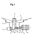
- Fig. 1 shows a cross section of the lower part of a dishwasher with a crushing device according to the present invention.
- the sump 1 which is the washing container (not completely shown) of the dishwasher closes down.
- a sieve arrangement 2 and 3 is provided which consists essentially of a fine sieve 2 and a coarse sieve 3 integrated therein.
- the rinsing liquid in the rinsing container flows down through the sieve arrangement 2 and 3 and collects at the bottom of the sump 1. From there, the rinsing liquid is either pumped during rinsing by the circulating pump 6 again in the transport paths for the rinsing liquid or pumping operation by a Reuse 5 removed via the drain pump 4 from the dishwasher.
- the crushing device consists essentially of a connection axis 8, which is rotatably supported via two bearings 9 and 10 at the bottom of the pump pot 1 and slidably mounted in the axial direction.
- the connection axis 8 has two free ends, wherein the one free end is equipped with the crushing blades 12, which comminute the coarse dirt at the bottom of the pump pot 1 during operation of the crushing device.
- the other free end 18 of the connecting shaft 8 is coupled to the impeller 7 of the circulating pump 6.
- Fig. 2 shows a detail view of in Fig.1 illustrated cross section of the lower part of the dishwasher with a crushing device according to the present invention Invention.
- Fig. 2 can be seen that the crushing device essentially has a connection axis 8, which is rotatably supported by two bearings 9 and 10 at the bottom of the pump pot 1 and slidably mounted in the axial direction.
- the connection axis 8 is shown in an axially shifted to the left position in which the crushing blades 12 opposite free end 18 of the connecting shaft 8 from the impeller 7 of the circulation pump 6 is spaced and decoupled.
- two radial projections in the form of discs 16 are provided between the two bearings, between which the actuating element 14 of a coupling controller 13 engages.
- the two radial discs 16 on the connecting shaft 8 thus form a sliding bearing, via which the connecting shaft 8 can be acted upon by the actuating element 14 of the coupling regulator 13 with force in both axial directions to effect the axial displacement of the connecting shaft 8 or the connecting shaft 8 in to maintain a desired axial position.
- the coupling controller 13 is a positive temperature coefficient (PTC) which is in heat-conducting contact with the actuating element 14.
- the actuator 14 is made of a shape memory alloy (FGL) which has the property of assuming given shapes at certain temperatures.
- FGL shape memory alloy
- the shape-memory alloy of the actuator 14 is set to assume a first predetermined shape at a first temperature, thereby displacing the connecting shaft 8 axially to the left via the slide bearing 16 in such a position the drive coupling between the connecting shaft 8 and the impeller 7 of the circulating pump 6 is interrupted, and at a second temperature assumes a second predetermined shape 15, while the connecting shaft 8 via the slide bearing 16 in such a position moves axially to the right, in which the drive coupling between the connecting axis 8 and the impeller 7 of the circulating pump 6 is made.
- the positive-temperature coefficient of the coupling regulator 13 may be electrically heated to provide the shape-memory alloy of the heat-conductive contact To heat actuator 14 to the desired temperature. With the aid of the positive temperature coefficient 13, the actuating element 14 can thus be brought to the first or second temperature, which then assumes the corresponding first 14 or second mold 15 and thereby the drive coupling between the connecting axis 8 of the comminution device and the impeller 7 of the circulation pump 6 turns on or off.
- the activation or deactivation of the coupling regulator 13 takes place via electrical connections 11, which are connected to an electronic control of the dishwasher. While the actuating element 14 is located inside the pump pot 1, the coupling regulator 13 is arranged outside the pump pot 1 in order to protect it from the influences of the flushing liquid and to prevent contact of the flushing liquid with the power supply 11 to the coupling regulator 13.
- the free end 18 of the connecting shaft 8 of the comminuting device comes into contact with the hub of the impeller 7 of the circulation pump 6.
- the drive coupling between the connecting axis 8 and the impeller 7 of the circulating pump 6 via a slip clutch is designed so that the driving force is transmitted by mutual friction of the two coupling components.
- the comminuting device Due to the drive coupling between the connection axis 8 of the comminution device and the impeller 7 of the circulation pump 6 via a slip clutch 17, 18, the comminuting device can be arbitrarily switched on or off during the flushing operation, without interrupting the operation of the circulation pump 6 or obstruct. Further, upon blocking of the crushing blades 12, the slip clutch 17, 18 may slip without damaging the circulation pump 6 or interrupting its operation.
Landscapes
- Engineering & Computer Science (AREA)
- Water Supply & Treatment (AREA)
- Structures Of Non-Positive Displacement Pumps (AREA)
- Washing And Drying Of Tableware (AREA)
- Processing Of Solid Wastes (AREA)
Description
- Gegenstand der Erfindung ist ein Geschirrspüler mit einer Vorrichtung zum Zerkleinern von Spülrückständen.
- Beim Reinigen von Spülgut in einem Geschirrspüler fallen üblicherweise Spülrückstände an, die sich am Boden des Geschirrspülers sammeln. Ein Teil der Spülrückstände ist dabei oft zu grob oder zu schwer, so dass er nach dem Spülvorgang nicht zusammen mit der verbrauchten Spülflotte über die Laugenpumpe aus dem Geschirrspüler abtransportiert werden kann. Infolgedessen lagern sich diese groben Spülrückstände in den Transportwegen der Spülflüssigkeit ab oder setzen die im Geschirrspüler vorhandenen Siebe zu, was den Betrieb des Geschirrspülers stark beeinträchtigen kann.
- Zur Beseitigung dieses Problems sind bereits Siebeinrichtungen bekannt, die aus dem Geschirrspüler entnommen, gereinigt und wieder eingesetzt werden können. Solche Siebeinrichtungen haben den Nachteil, dass der Reinigungsvorgang für den Benutzer unangenehm ist. Ferner wird der Reinigungsvorgang häufig vergessen oder zu selten durchgeführt, so dass ein einwandfreier Betrieb des Geschirrspülers aufgrund der Verstopfung der Siebeinrichtungen und der Behinderung in den Transportwegen der Spülflüssigkeit nicht mehr gewährleistet ist, was das Spülergebnis nachteilig beeinträchtigt und im Extremfall bis zur Zerstörung des Geschirrspülers führen kann.
- Bei weiteren bekannten Geschirrspülern ist eine Zerkleinerungsvorrichtung (Häcksler) vorgesehen, mit deren Hilfe die während des Spülvorgangs im Geschirrspüler anfallenden Spülrückstände soweit zerkleinert werden, dass sie im zerkleinerten Zustand zusam men mit der verbrauchten Spülflotte über die Laugenpumpe aus dem Geschirrspüler abtransportiert werden können. Die bekannten Zerkleinerungsvorrichtungen haben jedoch den Nachteil, dass sie über einen eigenen Motor angetrieben werden müssen. Da die Motoren einer der kostenintensivsten Komponenten in einem Geschirrspüler sind, stellen sie einen großen Anteil an den Gesamtherstellungskosten eines Geschirrspülers dar. Jeder zusätzliche Motor erhöht folglich die Herstellungskosten eines Geschirrspülers und auch die Gefahr einer Betriebsstörung.
- Eine Geschirrspülmaschine nach dem Oberbegriff des unabhängigen Anspruchs 1 ist aus dem Dokument
EP-A-1 057 445 bereits bekannt. - Aufgabe der vorliegenden Erfindung ist es daher, einen Geschirrspüler mit einer Zerkleinerungsvorrichtung bei geringen Herstellungskosten bereitzustellen, mit der es möglich ist, den beim Spülbetrieb anfallenden Grobschmutz auf einfache Weise in der Geschirrspülmaschine zu zerkleinern, aus dem Geschirrspüler abzutransportieren und damit sowohl das Spülergebnis als auch die Wartungsfreundlichkeit der Geschirrspülmaschine zu verbessern.
- Diese Aufgabe wird durch den erfindungsgemäßen Geschirrspüler mit den Merkmalen gemäß Anspruch 1 gelöst. Vorteilhafte Weiterbildungen der vorliegenden Erfindung sind in den Unteransprüchen 2 bis 10 gekennzeichnet.
- Beim erfindungsgemäßen Geschirrspüler ist eine Umwälzpumpe zum Umwälzen der Spülflüssigkeit und eine Zerkleinerungsvorrichtung zum Zerkleinern von Spülrückständen vorgesehen, wobei die Zerkleinerungsvorrichtung durch die Umwälzpumpe zumindest zeitweise angetrieben wird.
- Der Geschirrspüler mit einer Zerkleinerungsvorrichtung gemäß der vorliegenden Erfindung hat den Vorteil, dass die Zerkleinerungsvorrichtung auf einfache und effiziente Weise angetrieben wird, was sowohl eine kostengünstige Herstellung des Geschirrspülers ermöglicht als auch die Betriebssicherheit der Geschirrspülmaschine verbessert. Die Zerkleinerungsvorrichtung ist beispielsweise mit mehreren Zerkleinerungsmessern ausgestattet, die bei hohen Umdrehungen den Grobschmutz zerkleinern. Dadurch wird der beim Spülbetrieb anfallende Grobschmutz in der Geschirrspülmaschine soweit zerkleinert, dass dieser zusammen mit der verbrauchten Spülflüssigkeit aus der Geschirrspülmaschine abtransportiert werden kann, was sowohl das Spülergebnis verbessert als auch die Wartungsfreundlichkeit der Geschirrspülmaschine verbessert.
- Bei dem erfindungsgemäßen Geschirrspüler kann die Zerkleinerungsvorrichtung auch nur zeitweise betrieben, d.h. nur bei Bedarf gezielt zu- bzw. abgeschaltet werden. Die Aktivierung der Zerkleinerungsvorrichtung kann beispielsweise nur dann erfolgen, wenn grobe Spülrückstände im Geschirrspüler anfallen, wie z:B. während der Vorspülphase oder beim Reinigungsvorgang. Der temporäre Betrieb der Zerkleinerungsvorrichtung hat den Vorteil, dass die Zerkleinerungsvorrichtung nur bei Bedarf angetrieben werden kann, wodurch einerseits der Energieverbrauch für den Antrieb der Zerkleinerungsvorrichtung möglichst gering gehalten und andererseits die Zerkleinerungsvorrichtung selbst geschont wird.
- Bei einer vorteilhaften Ausführungsform des Geschirrspülers mit einer Zerkleinerungsvorrichtung gemäß der vorliegenden Erfindung erfolgt die Antriebskopplung zwischen der Zerkleinerungsvorrichtung und der Umwälzpumpe über eine Rutschkupplung, bei der die Antriebskraft durch gegenseitige Reibung der beiden Kupplungskomponenten übertragen wird. Dadurch kann die Zerkleinerungsvorrichtung während des Spülbetriebs beliebig zu- oder abgeschaltet werden, ohne den Betrieb der Umwälzpumpe zu unterbrechen. Aufgrund der Rutschkupplung wird verhindert, dass bei Blockierung der Zerkleinerungsvorrichtung beispielsweise durch Verhakung der Zerkleinerungsmesser mit nicht zerkleinerbaren Gegenständen oder herabgefallenen Besteckteilen, an der Zerkleinerungsvorrichtung oder an den Besteckteilen ein Schaden entsteht.
- Dabei ist es von besonderem Vorteil, wenn der Antrieb der Zerkleinerungsvorrichtung über das Flügelrad der Umwälzpumpe erfolgt. Durch das Flügelrad der Umwälzpumpe wird die Spülflüssigkeit in der Geschirrspülmaschine umgewälzt, d.h. in die dafür vorgesehenen Transportwege gepumpt. Infolgedessen ist das Flügelrad auch einer der Bauteile der Umwälzpumpe, das sich mit den höchsten Umdrehungen dreht. Da auch die Zerkleinerungsvorrichtung zur Erzielung einer guten Zerkleinerungswirkung vorzugsweise mit hohen Umdrehungen betrieben wird, eignet sich das Flügelrad der Umwälzpumpe besonders für den Antrieb der Zerkleinerungsvorrichtung, ohne dass ein Getriebe dazwischen vorgesehen werden muss.
- Der temporäre Antrieb der Zerkleinerungsvorrichtung lässt sich auf besonders einfache Weise realisieren, wenn die Antriebskopplung zwischen der Zerkleinerungsvorrichtung und der Umwälzpumpe mittels einer Verbindungswelle hergestellt wird. Die Verbindungswelle ist dabei vorzugsweise axial verschiebbar und in ihrer axialen Bewegungsfreiheit durch Anschläge begrenzt, wobei in der einen Anschlagstellung der Verbindungswelle die Antriebskopplung zwischen der Zerkleinerungsvorrichtung und der Umwälzpumpe hergestellt ist und in der anderen Anschlagstellung der Verbindungswelle die Antriebskopplung zwischen der Zerkleinerungsvorrichtung und der Umwälzpumpe unterbrochen ist. Auf diese Weise kann die Antriebskopplung zwischen der
- Zerkleinerungsvorrichtung und der Umwälzpumpe lediglich durch eine axiale Verschiebung der Verbindungswelle zwischen der Zerkleinerungsvorrichtung und der Umwälzpumpe wahlweise hergestellt oder unterbrochen werden.
- Zweckmäßigerweise kann die Verbindungswelle zwischen der Zerkleinerungsvorrichtung und der Umwälzpumpe an der Nabe des Flügelrads der Umwälzpumpe ankoppeln, wobei die Verbindungswelle zumindest ein freies Ende in Richtung der Umwälzpumpe aufweist. Durch die axiale Verschiebung der Verbindungswelle zwischen der Zerkleinerungsvorrichtung und der Umwälzpumpe in Richtung der Umwälzpumpe kann die Verbindungswelle mit ihrem freien Ende der Nabe des Flügelrads der Umwälzpumpe soweit angenähert und mit ihr in Kontakt gebracht werden, bis die Verbindungswelle und das Flügelrad der Umwälzpumpe miteinander gekoppelt sind. Wie oben erwähnt, sind dabei das freie Ende der Verbindungswelle und die Nabe des Flügelrads der Umwälzpumpe vorzugsweise so gestaltet, dass sie eine Rutschkupplung darstellen, bei der die Antriebskraft durch gegenseitige Reibung zwischen der Verbindungswelle und dem Flügelrad der Umwälzpumpe übertragen wird. Alternativ können das freie Ende der Verbindungswelle und die Nabe des Flügelrads der Umwälzpumpe auch mit einer derart zueinander komplementären Form gestaltet sein, dass sie ohne die Möglichkeit einer Differenz in der Umdrehungszahl ineinander greifen können.
- Um die Antriebskopplung zwischen der Zerkleinerungsvorrichtung und der Umwälzpumpe gezielt ein- bzw. abschalten zu können, ist vorzugsweise ein Kopplungsregler vorgesehen, durch den die Antriebskopplung hergestellt oder unterbrochen werden kann. Der Kopplungsregler kann beispielsweise eine Kombination aus einem Positiv-Temperatur-Koeffizienten (PTC) und einem aus einer Form-Gedächtnis-Legierung (FGL) bestehenden Betätigungselement umfassen, das auf die Antriebskopplung zwischen der Zerkleinerungsvorrichtung und der Umwälzpumpe mechanisch einwirkt und sie dadurch ein- bzw. abschaltet.
- Das Betätigungselement aus einer Form-Gedächtnis-Legierung hat die Eigenschaft bei bestimmten Temperaturen vorgegebene Formen anzunehmen, während der Positiv-Temperatur-Koeffizient elektrisch erhitzt werden kann, mit dem Betätigungselement aus einer Form-Gedächtnis-Legierung im wärmeleitenden Kontakt steht und es somit erwärmt. Für die Verwendung gemäß der vorliegenden Erfindung ist das Betätigungselement aus einer Form-Gedächtnis-Legierung beispielsweise so eingestellt, dass es bei einer ersten Temperatur eine erste vorgegebene Form annimmt, wodurch die Antriebskopplung zwischen der Zerkleinerungsvorrichtung und der Umwälzpumpe unterbrochen ist, und bei einer zweiten Temperatur eine zweite vorgegebene Form annimmt, wodurch die Antriebskopplung zwischen der Zerkleinerungsvorrichtung und der Umwälzpumpe hergestellt ist. Mit Hilfe des Positiv-Temperatur-Koeffizient kann das Betätigungselement aus einer Form-Gedächtnis-Legierung auf die erste oder zweite Temperatur gebracht werden, das daraufhin die entsprechende erste oder zweite Form annimmt und dadurch die Antriebskopplung zwischen der Zerkleinerungsvorrichtung und der Umwälzpumpe ein- bzw. abschaltet. Die Aktivierung bzw. Deaktivierung der Kombination aus einem Positiv-Temperatur-Koeffizienten und einem aus einer Form-Gedächtnis-Legierung bestehenden Betätigungselement erfolgt dabei vorzugsweise durch eine elektronische Steuerung der Geschirrspülmaschine.
- Bei einer weiteren vorteilhaften Ausführungsform der vorliegenden Erfindung, sind an der Verbindungswelle zwischen der Zerkleinerungsvorrichtung und der Umwälzpumpe zumindest zwei radiale Vorsprünge vorgesehen, zwischen die ein Betätigungselement des Kopplungsreglers eingreift. Durch die beiden radialen Vorsprünge an der Verbindungswelle wird ein Gleitlager für das Betätigungselement des Kopplungsreglers geschaffen, über das die Verbindungswelle mit Kraft in beiden axialen Richtungen beaufschlagt werden kann, um die axiale Verschiebung der Verbindungswelle zu bewirken oder die Verbindungswelle in einer gewünschten axialen Stellung zu halten.
- Alternativ kann die Antriebskopplung zwischen der Zerkleinerungsvorrichtung und der Umwälzpumpe auch durch einen elektromagnetischen Schalter hergestellt oder unterbrochen werden, der durch elektromagnetische Krafteinwirkung die axiale Verschiebung der Verbindungswelle zwischen der Zerkleinerungsvorrichtung und der Umwälzpumpe bewirkt. Der elektromagnetischen Schalter funktioniert nach dem Prinzip einer von elektrischem Strom durchflossenen Spule die einen Ferritkern umgibt, wobei die Verbindungsachse für die Antriebskopplung zwischen der Zerkleinerungsvorrichtung und der Umwälzpumpe den Ferritkern darstellt. Die Spule des elektromagnetischen Schalters umgibt die Verbindungsachse zumindest teilweise, so dass sie auf die Verbindungsachse eine Kraft in axialer Richtung ausübt, sobald die Spule von elektrischem Strom durchflossen wird. Wenn die Spule von elektrischem Strom in einer ersten Polung durchflossen wird, erzeugt die Spule an der Verbindungsachse eine axiale Kraft in einer ersten Richtung, wenn die Spule von elektrischem Strom in einer der ersten Polung entgegengesetzten Polung durchflossen wird, erzeugt die Spule an der Verbindungsachse eine axiale Kraft in einer der ersten Richtung entgegengesetzten Richtung. Auf diese Weise kann die Verbindungswelle zwischen der Zerkleinerungsvorrichtung und der Umwälzpumpe wahlweise mit Kraft in beiden axialen Richtungen beaufschlagt werden, um die axiale Verschiebung der Verbindungswelle zu bewirken oder die Verbindungswelle in einer gewünschten axialen Anschlagstellung zu halten.
- Besonders vorteilhaft ist es, wenn die Zerkleinerungsvorrichtung innerhalb und der Kopplungsregler außerhalb eines Spülbehälters des Geschirrspülers angeordnet ist. Eine solche Anordnung hat den Vorteil, dass der Positiv-Temperatur-Koeffizient (PTC), der das aus einer Form-Gedächtnis-Legierung (FGL) bestehende Betätigungselement steuert bzw. die Spule des elektromagnetischen Schalters, außerhalb des Spülbehälters angeordnet ist, und damit vor den wechselnden Temperaturen der Spülflüssigkeit geschützt wird. Ferner wird auch ein Kontakt der Stromversorgung des Positiven-Temperatur-Koeffizienten bzw. der Spule des elektromagnetischen Schalters mit der Spülflüssigkeit verhindert und damit die Betriebssicherheit der erfindungsgemäßen Geschirrspülmaschine gewährleistet.
- Im folgenden wird die vorliegende Erfindung anhand eines Ausführungsbeispiels unter Bezugnahme auf die Zeichnungen näher erläutert. Es zeigen:
- Figur 1
- einen Querschnitt vom unteren Teil eines Geschirrspülers mit einer Zerkleinerungsvorrichtung gemäß der vorliegenden Erfindung;
- Figur 2
- eine Detailansicht des in
Fig.1 dargestellten Querschnitts vom unteren Teil eines Geschirrspülers mit einer Zerkleinerungsvorrichtung gemäß der vorliegenden Erfindung. -
Fig. 1 zeigt einen Querschnitt vom unteren Teil eines Geschirrspülers mit einer Zerkleinerungsvorrichtung gemäß der vorliegenden Erfindung. Im unteren Teil der Geschirrspülmaschine befindet sich der Pumpentopf 1, der den Spülbehälter (nicht vollständig dargestellt) des Geschirrspülers nach unten abschließt. Im oberen Teil des Pumpentopfes 1 ist eine Siebanordnung 2 und 3 vorgesehen, die im wesentlichen aus einem Feinsieb 2 und einem darin integrierten Grobsieb 3 besteht. Während des Spülbetriebs fließt die Spülflüssigkeit im Spülbehälter nach unten durch die Siebanordnung 2 und 3 und sammelt sich am Boden des Pumpentopfes 1. Von dort wird die Spülflüssigkeit entweder beim Spülbetrieb von der Umwälzpumpe 6 wieder in die Transportwege für die Spülflüssigkeit gepumpt oder beim Abpumpbetrieb durch eine Reuse 5 über die Laugenpumpe 4 aus dem Geschirrspüler abtransportiert. - Insbesondere während der Vorspülphase und der Reinigungsvorgänge sammeln sich in einem Bereich vor der Reuse 5 an der untersten Stelle des Pumpentopfes 1 grobe Spülrückstände an, die durch das Grobsieb 3 durchgefallen sind und beim Abpumpen der verbrauchten Spülflüssigkeit nicht durch die Reuse 5 über die Laugenpumpe 4 aus dem Geschirrspüler abtransportiert werden können. In diesem Bereich befinden sich Zerkleinerungsmesser 12 einer Zerkleinerungsvorrichtung, die in eine Rotationsbewegung mit hohen Umdrehungen versetzt werden können, um den angesammelten Grobschmutz zu zerkleinern. In zerkleinerter Form können die Spülrückstände dann durch die Reuse 5 über die Laugenpumpe 4 beim Abpumpen der verbrauchten Spülflüssigkeit aus dem Geschirrspüler abtransportiert werden.
- Die Zerkleinerungsvorrichtung besteht im wesentlichen aus einer Verbindungsachse 8, die über zwei Lager 9 und 10 am Boden des Pumpentopfes 1 drehbar und in axialer Richtung verschiebbar gelagert ist. Die Verbindungsachse 8 weist zwei freie Enden auf, wobei das eine freie Ende mit den Zerkleinerungsmessern 12 bestückt ist, die beim Betrieb der Zerkleinerungsvorrichtung den Grobschmutz am Boden des Pumpentopfes 1 zerkleinern. Das andere freie Ende 18 der Verbindungsachse 8 ist mit dem Flügelrad 7 der Umwälzpumpe 6 gekoppelt. Beim Spülbetrieb wird das Flügelrad 7 von der Umwälzpumpe 6 angetrieben und dabei in eine Rotation mit hohen Umdrehungen gebracht, wobei durch die direkte Kopplung des Flügelrads 7 mit der Verbindungsachse 8 der Zerkleinerungsvorrichtung die Zerkleinerungsmesser 12 in die gleiche Rotation mit hohen Umdrehungen versetzt werden.
-
Fig. 2 zeigt eine Detailansicht des inFig.1 dargestellten Querschnitts vom unteren Teil des Geschirrspülers mit einer Zerkleinerungsvorrichtung gemäß der vorliegenden Erfindung.Fig. 2 lässt sich entnehmen, dass die Zerkleinerungsvorrichtung im wesentlichen eine Verbindungsachse 8 aufweist, die über zwei Lager 9 und 10 am Boden des Pumpentopfes 1 drehbar und in axialer Richtung verschiebbar gelagert ist. InFig. 2 ist die Verbindungsachse 8 in einer axial nach links verschobenen Position dargestellt, in der das den Zerkleinerungsmessern 12 gegenüberliegende freie Ende 18 der Verbindungsachse 8 vom Flügelrad 7 der Umwälzpumpe 6 beabstandet und damit entkoppelt ist. - An der Verbindungswelle 8 sind zwischen den beiden Lagerungen 9 und 10 zwei radiale Vorsprünge in Form von Scheiben 16 vorgesehen, zwischen die das Betätigungselement 14 eines Kopplungsreglers 13 eingreift. Die beiden radialen Scheiben 16 an der Verbindungswelle 8 bilden somit ein Gleitlager, über das die Verbindungswelle 8 durch das Betätigungselement 14 des Kopplungsreglers 13 mit Kraft in beiden axialen Richtungen beaufschlagt werden kann, um die axiale Verschiebung der Verbindungswelle 8 zu bewirken oder die Verbindungswelle 8 in einer gewünschten axialen Stellung zu halten.
- Bei dem Kopplungsregler 13 handelt es sich um einen Positiv-Temperatur-Koeffizienten (PTC) der mit dem Betätigungselement 14 in wärmeleitendem Kontakt steht. Das Betätigungselement 14 besteht aus einer Form-Gedächtnis-Legierung (FGL), das die Eigenschaft hat, bei bestimmten Temperaturen vorgegebene Formen anzunehmen. Bei dem in den Zeichnungen dargestellten Ausführungsbeispiel ist die Form-Gedächtnis-Legierung des Betätigungselements 14 so eingestellt, dass es bei einer ersten Temperatur eine erste vorgegebene Form annimmt und dabei die Verbindungsachse 8 über das Gleitlager 16 in eine solche Position axial nach links verschiebt, bei der die Antriebskopplung zwischen der Verbindungsachse 8 und dem Flügelrad 7 der Umwälzpumpe 6 unterbrochen ist, und bei einer zweiten Temperatur eine zweite vorgegebene Form 15 annimmt und dabei die Verbindungsachse 8 über das Gleitlager 16 in eine solche Position axial nach rechts verschiebt, bei der die Antriebskopplung zwischen der Verbindungsachse 8 und dem Flügelrad 7 der Umwälzpumpe 6 hergestellt ist.
- Der Positiv-Temperatur-Koeffizient des Kopplungsreglers 13 kann elektrisch erhitzt werden, um über den wärmeleitenden Kontakt die Form-Gedächtnis-Legierung des Betätigungselements 14 auf die gewünschte Temperatur zu erwärmen. Mit Hilfe des Positiv-Temperatur-Koeffizienten 13 kann somit das Betätigungselement 14 auf die erste oder zweite Temperatur gebracht werden, das daraufhin die entsprechende erste 14 oder zweite Form 15 annimmt und dadurch die Antriebskopplung zwischen Verbindungsachse 8 der Zerkleinerungsvorrichtung und dem Flügelrad 7 der Umwälzpumpe 6 ein- bzw. abschaltet.
- Die Aktivierung bzw. Deaktivierung des Kopplungsreglers 13 erfolgt über elektrische Anschlüsse 11, die mit einer elektronischen Steuerung der Geschirrspülmaschine verbunden sind. Während sich das Betätigungselement 14 innerhalb des Pumpentopfes 1 befindet, ist der Kopplungsregler 13 außerhalb des Pumpentopfes 1 angeordnet, um ihn vor den Einflüssen der Spülflüssigkeit zu schützen und einen Kontakt der Spülflüssigkeit mit der Stromversorgung 11 zum Kopplungsregler 13 zu verhindern.
- Wenn sich das Betätigungselement 14 in der Position 15 befindet, in der es die Verbindungsachse 8 über das Gleitlager 16 axial nach rechts verschiebt, kommt das freie Ende 18 der Verbindungsachse 8 der Zerkleinerungsvorrichtung mit der Nabe des Flügelrads 7 der Umwälzpumpe 6 in Kontakt. Bei dem vorliegenden Ausführungsbeispiel erfolgt die Antriebskopplung zwischen der Verbindungsachse 8 und dem Flügelrad 7 der Umwälzpumpe 6 über eine Rutschkupplung. Dabei ist das freie Ende 18 der Verbindungsachse 8 der Zerkleinerungsvorrichtung und die Nabe des Flügelrads 7 der Umwälzpumpe 6 so gestaltet, dass die Antriebskraft durch gegenseitige Reibung der beiden Kupplungskomponenten übertragen wird.
- Aufgrund der Antriebskopplung zwischen der Verbindungsachse 8 der Zerkleinerungsvorrichtung und dem Flügelrad 7 der Umwälzpumpe 6 über eine Rutschkupplung 17, 18 kann die Zerkleinerungsvorrichtung während des Spülbetriebs beliebig zu- oder abgeschaltet werden, ohne den Betrieb der Umwälzpumpe 6 zu unterbrechen oder zu behindern. Ferner kann bei einer Blockierung der Zerkleinerungsmesser 12 die Rutschkupplung 17, 18 durchrutschen, ohne die Umwälzpumpe 6 zu beschädigen oder ihren Betrieb zu unterbrechen.
-
- 1
- Pumpentopf
- 2
- Feinsieb
- 3
- Grobsieb
- 4
- Laugenpumpe
- 5
- Reuse
- 6
- Umwälzpumpe
- 7
- Flügelrad der Umwälzpumpe 6
- 8
- Verbindungsachse der Zerkleinerungsvorrichtung
- 9
- Lagerung der Zerkleinerungsvorrichtung
- 10
- Lagerung der Zerkleinerungsvorrichtung
- 11
- elektrische Anschlüsse des Kopplungsreglers 13
- 12
- Zerkleinerungsmesser der Zerkleinerungsvorrichtung
- 13
- Kopplungsregler (Positiv-Temperatur-Koeffizient, PTC)
- 14
- Betätigungselement (Form-Gedächtnis-Legierung, FGL) des Kopplungsreglers 13
- 15
- zweite Position des Betätigungselements
- 16
- radiale Scheiben/Gleitlager auf der Verbindungsachse 8
- 17
- Nabe des Flügelrads 7
- 18
- freies Ende der Verbindungsachse 8
Claims (10)
- Geschirrspüler mit einer Umwälzpumpe (6) zum Umwälzen der Spülflüssigkeit und einer Zerkleinerungsvorrichtung (12) zum Zerkleinern von Spülrückständen
dadurch gekennzeichnet, dass die Zerkleinerungsvorrichtung (12) mit der Umwälzpumpe derart gekoppelt werden kann, dass die Zerkleinerungsvorrichtung (12) zumindest zeitweise während des Umwälzpumpebetriebs durch diese (Umwälzpumpe (6)) angetrieben werden kann. - Geschirrspüler nach Anspruch 1, wobei eine Antriebskopplung zwischen der Zerkleinerungsvorrichtung (12) und der Umwälzpumpe (6) über eine Rutschkupplung (17, 18) erfolgt.
- Geschirrspüler nach einem der Ansprüche 1 oder 2, wobei der Antrieb der Zerkleinerungsvorrichtung (12) über ein Flügelrad (7) der Umwälzpumpe (6) erfolgt.
- Geschirrspüler nach einem der vorangehenden Ansprüche, wobei die Antriebskopplung zwischen der Zerkleinerungsvorrichtung (12) und der Umwälzpumpe (6) mittels einer vorzugsweise axial verschiebbaren Verbindungswelle (8) hergestellt wird.
- Geschirrspüler nach Anspruch 4, wobei die Antriebskopplung zwischen der Zerkleinerungsvorrichtung (12) und der Umwälzpumpe (6) durch eine axiale Verschiebung der Verbindungswelle (8) zwischen der Zerkleinerungsvorrichtung (12) und der Umwälzpumpe (6) wahlweise hergestellt oder unterbrochen wird.
- Geschirrspüler nach einem der Ansprüche 4 oder 5, wobei die Verbindungswelle zwischen der Zerkleinerungsvorrichtung (12) und der Umwälzpumpe (6) an der Nabe des Flügelrads (7) der Umwälzpumpe (6) ankoppeln kann.
- Geschirrspüler nach einem der vorangehenden Ansprüche, wobei die Antriebskopplung zwischen der Zerkleinerungsvorrichtung (12) und der Umwälzpumpe (6) durch einen Kopplungsregler (13, 14), insbesondere durch eine Kombination aus einem Positiven-Temperatur-Koeffizienten (3) und einem aus einer Form-Gedächtnis-Legierung bestehenden Betätigungselement (14) hergestellt oder unterbrochen werden kann.
- Geschirrspüler nach einem der Ansprüche 4 bis 7, wobei an der Verbindungswelle (8) zwischen der Zerkleinerungsvorrichtung (12) und der Umwälzpumpe (6) zumindest zwei radiale Vorsprünge (16) vorgesehen sind, zwischen die ein Betätigungselement (14) des Kopplungsreglers (13, 14) eingreift, um eine die axiale Verschiebung der Verbindungswelle (8) zu bewirken.
- Geschirrspüler nach einem der Ansprüche 4 bis 8, wobei die Antriebskopplung zwischen der Zerkleinerungsvorrichtung (12) und der Umwälzpumpe (6) durch einen elektromagnetischen Schalter hergestellt oder unterbrochen werden kann, der durch elektromagnetische Krafteinwirkung die axiale Verschiebung der Verbindungswelle (8) zwischen der Zerkleinerungsvorrichtung (12) und der Umwälzpumpe (6) bewirkt.
- Geschirrspüler nach einem der vorangehenden Ansprüche, wobei die Zerkleinerungsvorrichtung (12) innerhalb und der Kopplungsregler (13, 14) außerhalb eines Spülbehälters des Geschirrspülers angeordnet ist.
Priority Applications (1)
| Application Number | Priority Date | Filing Date | Title |
|---|---|---|---|
| PL04790209T PL1677663T3 (pl) | 2003-10-08 | 2004-10-08 | Zmywarka do naczyń z urządzeniem rozdrabniającym |
Applications Claiming Priority (2)
| Application Number | Priority Date | Filing Date | Title |
|---|---|---|---|
| DE10346675A DE10346675A1 (de) | 2003-10-08 | 2003-10-08 | Geschirrspüler mit Zerkleinerungsvorrichtung |
| PCT/EP2004/011271 WO2005034714A1 (de) | 2003-10-08 | 2004-10-08 | Geschirrspüler mit zerkleinerungsvorrichtung |
Publications (2)
| Publication Number | Publication Date |
|---|---|
| EP1677663A1 EP1677663A1 (de) | 2006-07-12 |
| EP1677663B1 true EP1677663B1 (de) | 2009-12-23 |
Family
ID=34399352
Family Applications (1)
| Application Number | Title | Priority Date | Filing Date |
|---|---|---|---|
| EP04790209A Expired - Lifetime EP1677663B1 (de) | 2003-10-08 | 2004-10-08 | Geschirrspüler mit zerkleinerungsvorrichtung |
Country Status (8)
| Country | Link |
|---|---|
| US (1) | US8382914B2 (de) |
| EP (1) | EP1677663B1 (de) |
| CN (1) | CN1867290B (de) |
| AT (1) | ATE452575T1 (de) |
| DE (2) | DE10346675A1 (de) |
| ES (1) | ES2337151T3 (de) |
| PL (1) | PL1677663T3 (de) |
| WO (1) | WO2005034714A1 (de) |
Families Citing this family (29)
| Publication number | Priority date | Publication date | Assignee | Title |
|---|---|---|---|---|
| US7497222B2 (en) * | 2004-07-02 | 2009-03-03 | Bsh Bosch Und Siemens Hausgeraete | Comminution device and method for comminuting residue in a dishwasher |
| US8557053B2 (en) * | 2008-11-26 | 2013-10-15 | Electrolux Home Products, Inc. | Actuator assembly and associated apparatuses |
| US8667974B2 (en) * | 2009-12-21 | 2014-03-11 | Whirlpool Corporation | Rotating filter for a dishwashing machine |
| US8746261B2 (en) * | 2009-12-21 | 2014-06-10 | Whirlpool Corporation | Rotating drum filter for a dishwashing machine |
| US9918609B2 (en) * | 2009-12-21 | 2018-03-20 | Whirlpool Corporation | Rotating drum filter for a dishwashing machine |
| US9687135B2 (en) | 2009-12-21 | 2017-06-27 | Whirlpool Corporation | Automatic dishwasher with pump assembly |
| US9119515B2 (en) | 2010-12-03 | 2015-09-01 | Whirlpool Corporation | Dishwasher with unitary wash module |
| US8627832B2 (en) | 2010-12-13 | 2014-01-14 | Whirlpool Corporation | Rotating filter for a dishwashing machine |
| US9668636B2 (en) | 2010-11-16 | 2017-06-06 | Whirlpool Corporation | Method and apparatus for dishwasher with common heating element for multiple treating chambers |
| US9113766B2 (en) | 2010-11-16 | 2015-08-25 | Whirlpool Corporation | Method and apparatus for dishwasher with common heating element for multiple treating chambers |
| US9034112B2 (en) | 2010-12-03 | 2015-05-19 | Whirlpool Corporation | Dishwasher with shared heater |
| US8733376B2 (en) | 2011-05-16 | 2014-05-27 | Whirlpool Corporation | Dishwasher with filter assembly |
| US9107559B2 (en) | 2011-05-16 | 2015-08-18 | Whirlpool Corporation | Dishwasher with filter assembly |
| US20120318296A1 (en) | 2011-06-20 | 2012-12-20 | Whirlpool Corporation | Ultra micron filter for a dishwasher |
| US9265401B2 (en) | 2011-06-20 | 2016-02-23 | Whirlpool Corporation | Rotating filter for a dishwashing machine |
| US9010344B2 (en) | 2011-06-20 | 2015-04-21 | Whirlpool Corporation | Rotating filter for a dishwashing machine |
| US9861251B2 (en) | 2011-06-20 | 2018-01-09 | Whirlpool Corporation | Filter with artificial boundary for a dishwashing machine |
| US9005369B2 (en) | 2011-06-20 | 2015-04-14 | Whirlpool Corporation | Filter assembly for a dishwasher |
| US9301667B2 (en) | 2012-02-27 | 2016-04-05 | Whirlpool Corporation | Soil chopping system for a dishwasher |
| US9730570B2 (en) | 2012-05-30 | 2017-08-15 | Whirlpool Corporation | Reduced sound with a rotating filter for a dishwasher |
| US9237836B2 (en) | 2012-05-30 | 2016-01-19 | Whirlpool Corporation | Rotating filter for a dishwasher |
| US9451862B2 (en) | 2012-06-01 | 2016-09-27 | Whirlpool Corporation | Dishwasher with unitary wash module |
| US9532700B2 (en) | 2012-06-01 | 2017-01-03 | Whirlpool Corporation | Dishwasher with overflow conduit |
| US9833120B2 (en) | 2012-06-01 | 2017-12-05 | Whirlpool Corporation | Heating air for drying dishes in a dishwasher using an in-line wash liquid heater |
| US9554688B2 (en) | 2012-10-23 | 2017-01-31 | Whirlpool Corporation | Rotating filter for a dishwasher and methods of cleaning a rotating filter |
| US10813527B2 (en) * | 2017-08-29 | 2020-10-27 | Whirlpool Corporation | Blade and pump impeller assembly for a dishwasher |
| CN108378802A (zh) * | 2018-05-08 | 2018-08-10 | 东莞优乐家智能家电有限公司 | 一种厨余洗碗一体机 |
| CN113842093B (zh) * | 2021-08-26 | 2023-09-12 | 华帝股份有限公司 | 一种用于洗碗机的残渣粉碎方法 |
| BE1031791B1 (de) * | 2023-07-11 | 2025-02-11 | Miele & Cie | Haushaltsgerät, insbesondere wasserführendes Haushaltsgerät |
Family Cites Families (11)
| Publication number | Priority date | Publication date | Assignee | Title |
|---|---|---|---|---|
| US2918811A (en) * | 1955-10-04 | 1959-12-29 | Nat Rubber Machinery Co | Washing machine |
| US3981456A (en) * | 1975-10-31 | 1976-09-21 | General Electric Company | Food particle macerating means |
| DE3265454D1 (en) * | 1981-11-09 | 1985-09-19 | Hobart Corp | A dishwasher incorporating combination drain pump and grinding apparatus |
| JPH05176874A (ja) * | 1991-12-27 | 1993-07-20 | Hoshizaki Electric Co Ltd | 食器洗浄機のための制御装置 |
| DE4424257C2 (de) | 1994-07-09 | 1999-03-18 | Aweco Kunststofftech Geraete | Zentrifugalpumpe hoher Leistung mit Einphasensynchronmotorantrieb |
| IT1277428B1 (it) * | 1995-08-03 | 1997-11-10 | Whirlpool Italia S P A | Macchina lavastoviglie con pozzetto di fondo a zone distinte |
| CN2368446Y (zh) * | 1999-03-19 | 2000-03-15 | 罗宜恒 | 超声波全自动洗碗机 |
| US6454872B1 (en) * | 1999-06-04 | 2002-09-24 | Whirlpool Corporation | Dishwasher with food particle chopping assembly |
| ES2178909B1 (es) * | 1999-11-22 | 2004-02-16 | Fagor S Coop | Dispositivo triturador con conjunto cuchilla movil-cuchilla fija para una bomba de desague. |
| ITVR20010055A1 (it) | 2001-05-08 | 2002-11-08 | Esse 85 Srl | "aspirapolvere con filtro ad acqua" |
| ITPN20010034A1 (it) * | 2001-05-08 | 2002-11-08 | Electrolux Zanussi Elettrodome | Lavastoviglie con tritarifiuti |
-
2003
- 2003-10-08 DE DE10346675A patent/DE10346675A1/de not_active Withdrawn
-
2004
- 2004-10-08 EP EP04790209A patent/EP1677663B1/de not_active Expired - Lifetime
- 2004-10-08 WO PCT/EP2004/011271 patent/WO2005034714A1/de not_active Ceased
- 2004-10-08 ES ES04790209T patent/ES2337151T3/es not_active Expired - Lifetime
- 2004-10-08 PL PL04790209T patent/PL1677663T3/pl unknown
- 2004-10-08 AT AT04790209T patent/ATE452575T1/de not_active IP Right Cessation
- 2004-10-08 DE DE502004010556T patent/DE502004010556D1/de not_active Expired - Lifetime
- 2004-10-08 US US10/573,457 patent/US8382914B2/en not_active Expired - Fee Related
- 2004-10-08 CN CN2004800296611A patent/CN1867290B/zh not_active Expired - Fee Related
Also Published As
| Publication number | Publication date |
|---|---|
| CN1867290B (zh) | 2012-05-16 |
| ATE452575T1 (de) | 2010-01-15 |
| DE502004010556D1 (de) | 2010-02-04 |
| ES2337151T3 (es) | 2010-04-21 |
| CN1867290A (zh) | 2006-11-22 |
| EP1677663A1 (de) | 2006-07-12 |
| DE10346675A1 (de) | 2005-05-04 |
| WO2005034714A1 (de) | 2005-04-21 |
| US20070107753A1 (en) | 2007-05-17 |
| US8382914B2 (en) | 2013-02-26 |
| PL1677663T3 (pl) | 2010-06-30 |
Similar Documents
| Publication | Publication Date | Title |
|---|---|---|
| EP1677663B1 (de) | Geschirrspüler mit zerkleinerungsvorrichtung | |
| EP1765136B1 (de) | Geschirrspühler mit zerkleinerungsvorrichtung | |
| DE102012103435B4 (de) | Filteranordnung für einen Geschirrspüler | |
| DE60025974T2 (de) | Geschirrspülmaschine mit Vorrichtung zum Zerhacken von Nahrungspartikeln | |
| EP1862057B1 (de) | Vorsatzgerät zum Ernten von stängeligem Erntegut | |
| DE3730448C2 (de) | ||
| DE102012102184A1 (de) | Geschirrspüler mit Filteranordnung | |
| DE60125244T2 (de) | Monodirektionales Laufrad für elektrische Kreiselpumpen | |
| DE102012102182A1 (de) | Geschirrspüler mit Filteranordnung | |
| EP4140559B1 (de) | Filtervorrichtung für ein wasserführendes haushaltsgerät, wasserführendes haushaltsgerät und verfahren zum reinigen der filtervorrichtung | |
| DE69118102T2 (de) | Vorrichtung zum Anhalten der Trommel einer mantelbeschickbaren Trommelwaschmaschine in der Beschickungsposition | |
| EP2205140B1 (de) | Wasserführendes haushaltsgerät mit selbstreinigendem filter | |
| DE102008050895A1 (de) | Pumpe für Fluide | |
| DE102012110890A1 (de) | Rotationsfilteranordnung für einen Geschirrspüler | |
| EP2101064A1 (de) | Kühleinrichtung für ein Arbeitsfluid | |
| DE102016101834A1 (de) | Schleifvorrichtung für Häckselmesser eines Häckselwerks und Häckselwerk | |
| EP1520464B1 (de) | Häckseleinrichtung für einen Feldhäcksler | |
| EP3733040A1 (de) | Wasserführendes haushaltsgerät | |
| EP2326161B1 (de) | Akku-gartenschere | |
| DE10016290A1 (de) | Küchenmaschine | |
| EP1545282B1 (de) | Arbeitswerkzeug für küchengeräte | |
| EP2888986A1 (de) | Pumpe zum Abführen einer Flüssigkeit und Haushaltsgerät mit einer solchen Pumpe | |
| DE9419549U1 (de) | Waschmaschine | |
| DE19909100A1 (de) | Thermostatventilaufsatz | |
| EP3789169B1 (de) | Holzhackmaschine |
Legal Events
| Date | Code | Title | Description |
|---|---|---|---|
| PUAI | Public reference made under article 153(3) epc to a published international application that has entered the european phase |
Free format text: ORIGINAL CODE: 0009012 |
|
| 17P | Request for examination filed |
Effective date: 20060508 |
|
| AK | Designated contracting states |
Kind code of ref document: A1 Designated state(s): AT BE BG CH CY CZ DE DK EE ES FI FR GB GR HU IE IT LI LU MC NL PL PT RO SE SI SK TR |
|
| DAX | Request for extension of the european patent (deleted) | ||
| 17Q | First examination report despatched |
Effective date: 20071023 |
|
| GRAP | Despatch of communication of intention to grant a patent |
Free format text: ORIGINAL CODE: EPIDOSNIGR1 |
|
| GRAS | Grant fee paid |
Free format text: ORIGINAL CODE: EPIDOSNIGR3 |
|
| GRAA | (expected) grant |
Free format text: ORIGINAL CODE: 0009210 |
|
| AK | Designated contracting states |
Kind code of ref document: B1 Designated state(s): AT BE BG CH CY CZ DE DK EE ES FI FR GB GR HU IE IT LI LU MC NL PL PT RO SE SI SK TR |
|
| REG | Reference to a national code |
Ref country code: GB Ref legal event code: FG4D Free format text: NOT ENGLISH |
|
| REG | Reference to a national code |
Ref country code: CH Ref legal event code: EP |
|
| REG | Reference to a national code |
Ref country code: IE Ref legal event code: FG4D |
|
| REF | Corresponds to: |
Ref document number: 502004010556 Country of ref document: DE Date of ref document: 20100204 Kind code of ref document: P |
|
| REG | Reference to a national code |
Ref country code: ES Ref legal event code: FG2A Ref document number: 2337151 Country of ref document: ES Kind code of ref document: T3 |
|
| REG | Reference to a national code |
Ref country code: NL Ref legal event code: VDEP Effective date: 20091223 |
|
| PG25 | Lapsed in a contracting state [announced via postgrant information from national office to epo] |
Ref country code: FI Free format text: LAPSE BECAUSE OF FAILURE TO SUBMIT A TRANSLATION OF THE DESCRIPTION OR TO PAY THE FEE WITHIN THE PRESCRIBED TIME-LIMIT Effective date: 20091223 Ref country code: SE Free format text: LAPSE BECAUSE OF FAILURE TO SUBMIT A TRANSLATION OF THE DESCRIPTION OR TO PAY THE FEE WITHIN THE PRESCRIBED TIME-LIMIT Effective date: 20091223 |
|
| PG25 | Lapsed in a contracting state [announced via postgrant information from national office to epo] |
Ref country code: SI Free format text: LAPSE BECAUSE OF FAILURE TO SUBMIT A TRANSLATION OF THE DESCRIPTION OR TO PAY THE FEE WITHIN THE PRESCRIBED TIME-LIMIT Effective date: 20091223 |
|
| REG | Reference to a national code |
Ref country code: IE Ref legal event code: FD4D |
|
| PG25 | Lapsed in a contracting state [announced via postgrant information from national office to epo] |
Ref country code: RO Free format text: LAPSE BECAUSE OF FAILURE TO SUBMIT A TRANSLATION OF THE DESCRIPTION OR TO PAY THE FEE WITHIN THE PRESCRIBED TIME-LIMIT Effective date: 20091223 Ref country code: PT Free format text: LAPSE BECAUSE OF FAILURE TO SUBMIT A TRANSLATION OF THE DESCRIPTION OR TO PAY THE FEE WITHIN THE PRESCRIBED TIME-LIMIT Effective date: 20100423 Ref country code: NL Free format text: LAPSE BECAUSE OF FAILURE TO SUBMIT A TRANSLATION OF THE DESCRIPTION OR TO PAY THE FEE WITHIN THE PRESCRIBED TIME-LIMIT Effective date: 20091223 Ref country code: BG Free format text: LAPSE BECAUSE OF FAILURE TO SUBMIT A TRANSLATION OF THE DESCRIPTION OR TO PAY THE FEE WITHIN THE PRESCRIBED TIME-LIMIT Effective date: 20100323 Ref country code: EE Free format text: LAPSE BECAUSE OF FAILURE TO SUBMIT A TRANSLATION OF THE DESCRIPTION OR TO PAY THE FEE WITHIN THE PRESCRIBED TIME-LIMIT Effective date: 20091223 |
|
| PG25 | Lapsed in a contracting state [announced via postgrant information from national office to epo] |
Ref country code: SK Free format text: LAPSE BECAUSE OF FAILURE TO SUBMIT A TRANSLATION OF THE DESCRIPTION OR TO PAY THE FEE WITHIN THE PRESCRIBED TIME-LIMIT Effective date: 20091223 Ref country code: CZ Free format text: LAPSE BECAUSE OF FAILURE TO SUBMIT A TRANSLATION OF THE DESCRIPTION OR TO PAY THE FEE WITHIN THE PRESCRIBED TIME-LIMIT Effective date: 20091223 |
|
| PG25 | Lapsed in a contracting state [announced via postgrant information from national office to epo] |
Ref country code: GR Free format text: LAPSE BECAUSE OF FAILURE TO SUBMIT A TRANSLATION OF THE DESCRIPTION OR TO PAY THE FEE WITHIN THE PRESCRIBED TIME-LIMIT Effective date: 20100324 Ref country code: CY Free format text: LAPSE BECAUSE OF FAILURE TO SUBMIT A TRANSLATION OF THE DESCRIPTION OR TO PAY THE FEE WITHIN THE PRESCRIBED TIME-LIMIT Effective date: 20091223 Ref country code: IE Free format text: LAPSE BECAUSE OF FAILURE TO SUBMIT A TRANSLATION OF THE DESCRIPTION OR TO PAY THE FEE WITHIN THE PRESCRIBED TIME-LIMIT Effective date: 20091223 |
|
| PLBE | No opposition filed within time limit |
Free format text: ORIGINAL CODE: 0009261 |
|
| STAA | Information on the status of an ep patent application or granted ep patent |
Free format text: STATUS: NO OPPOSITION FILED WITHIN TIME LIMIT |
|
| 26N | No opposition filed |
Effective date: 20100924 |
|
| PG25 | Lapsed in a contracting state [announced via postgrant information from national office to epo] |
Ref country code: DK Free format text: LAPSE BECAUSE OF FAILURE TO SUBMIT A TRANSLATION OF THE DESCRIPTION OR TO PAY THE FEE WITHIN THE PRESCRIBED TIME-LIMIT Effective date: 20091223 |
|
| BERE | Be: lapsed |
Owner name: BSH BOSCH UND SIEMENS HAUSGERATE G.M.B.H. Effective date: 20101031 |
|
| PG25 | Lapsed in a contracting state [announced via postgrant information from national office to epo] |
Ref country code: MC Free format text: LAPSE BECAUSE OF NON-PAYMENT OF DUE FEES Effective date: 20101031 |
|
| REG | Reference to a national code |
Ref country code: CH Ref legal event code: PL |
|
| PG25 | Lapsed in a contracting state [announced via postgrant information from national office to epo] |
Ref country code: LI Free format text: LAPSE BECAUSE OF NON-PAYMENT OF DUE FEES Effective date: 20101031 Ref country code: CH Free format text: LAPSE BECAUSE OF NON-PAYMENT OF DUE FEES Effective date: 20101031 |
|
| PG25 | Lapsed in a contracting state [announced via postgrant information from national office to epo] |
Ref country code: BE Free format text: LAPSE BECAUSE OF NON-PAYMENT OF DUE FEES Effective date: 20101031 |
|
| REG | Reference to a national code |
Ref country code: AT Ref legal event code: MM01 Ref document number: 452575 Country of ref document: AT Kind code of ref document: T Effective date: 20101008 |
|
| PG25 | Lapsed in a contracting state [announced via postgrant information from national office to epo] |
Ref country code: AT Free format text: LAPSE BECAUSE OF NON-PAYMENT OF DUE FEES Effective date: 20101008 |
|
| PG25 | Lapsed in a contracting state [announced via postgrant information from national office to epo] |
Ref country code: HU Free format text: LAPSE BECAUSE OF FAILURE TO SUBMIT A TRANSLATION OF THE DESCRIPTION OR TO PAY THE FEE WITHIN THE PRESCRIBED TIME-LIMIT Effective date: 20100624 Ref country code: LU Free format text: LAPSE BECAUSE OF NON-PAYMENT OF DUE FEES Effective date: 20101008 |
|
| REG | Reference to a national code |
Ref country code: DE Ref legal event code: R081 Ref document number: 502004010556 Country of ref document: DE Owner name: BSH HAUSGERAETE GMBH, DE Free format text: FORMER OWNER: BSH BOSCH UND SIEMENS HAUSGERAETE GMBH, 81739 MUENCHEN, DE Effective date: 20150407 |
|
| REG | Reference to a national code |
Ref country code: ES Ref legal event code: PC2A Owner name: BSH HAUSGERATE GMBH Effective date: 20150527 |
|
| REG | Reference to a national code |
Ref country code: FR Ref legal event code: PLFP Year of fee payment: 12 |
|
| REG | Reference to a national code |
Ref country code: FR Ref legal event code: CD Owner name: BSH HAUSGERATE GMBH Effective date: 20151022 |
|
| REG | Reference to a national code |
Ref country code: FR Ref legal event code: PLFP Year of fee payment: 13 |
|
| REG | Reference to a national code |
Ref country code: FR Ref legal event code: PLFP Year of fee payment: 14 |
|
| REG | Reference to a national code |
Ref country code: FR Ref legal event code: PLFP Year of fee payment: 15 |
|
| PGFP | Annual fee paid to national office [announced via postgrant information from national office to epo] |
Ref country code: PL Payment date: 20180928 Year of fee payment: 15 Ref country code: TR Payment date: 20180926 Year of fee payment: 15 |
|
| PGFP | Annual fee paid to national office [announced via postgrant information from national office to epo] |
Ref country code: DE Payment date: 20181031 Year of fee payment: 15 |
|
| PGFP | Annual fee paid to national office [announced via postgrant information from national office to epo] |
Ref country code: IT Payment date: 20181022 Year of fee payment: 15 Ref country code: FR Payment date: 20181023 Year of fee payment: 15 Ref country code: ES Payment date: 20181122 Year of fee payment: 15 Ref country code: GB Payment date: 20181025 Year of fee payment: 15 |
|
| REG | Reference to a national code |
Ref country code: DE Ref legal event code: R119 Ref document number: 502004010556 Country of ref document: DE |
|
| PG25 | Lapsed in a contracting state [announced via postgrant information from national office to epo] |
Ref country code: DE Free format text: LAPSE BECAUSE OF NON-PAYMENT OF DUE FEES Effective date: 20200501 |
|
| GBPC | Gb: european patent ceased through non-payment of renewal fee |
Effective date: 20191008 |
|
| PG25 | Lapsed in a contracting state [announced via postgrant information from national office to epo] |
Ref country code: FR Free format text: LAPSE BECAUSE OF NON-PAYMENT OF DUE FEES Effective date: 20191031 Ref country code: GB Free format text: LAPSE BECAUSE OF NON-PAYMENT OF DUE FEES Effective date: 20191008 Ref country code: IT Free format text: LAPSE BECAUSE OF NON-PAYMENT OF DUE FEES Effective date: 20191008 |
|
| REG | Reference to a national code |
Ref country code: ES Ref legal event code: FD2A Effective date: 20210226 |
|
| PG25 | Lapsed in a contracting state [announced via postgrant information from national office to epo] |
Ref country code: ES Free format text: LAPSE BECAUSE OF NON-PAYMENT OF DUE FEES Effective date: 20191009 |
|
| PG25 | Lapsed in a contracting state [announced via postgrant information from national office to epo] |
Ref country code: PL Free format text: LAPSE BECAUSE OF NON-PAYMENT OF DUE FEES Effective date: 20191008 |
|
| PG25 | Lapsed in a contracting state [announced via postgrant information from national office to epo] |
Ref country code: TR Free format text: LAPSE BECAUSE OF NON-PAYMENT OF DUE FEES Effective date: 20191008 |