EP1678697B1 - Antidiebstahl-etikett - Google Patents
Antidiebstahl-etikett Download PDFInfo
- Publication number
- EP1678697B1 EP1678697B1 EP04796806A EP04796806A EP1678697B1 EP 1678697 B1 EP1678697 B1 EP 1678697B1 EP 04796806 A EP04796806 A EP 04796806A EP 04796806 A EP04796806 A EP 04796806A EP 1678697 B1 EP1678697 B1 EP 1678697B1
- Authority
- EP
- European Patent Office
- Prior art keywords
- line
- housing
- crimping
- theft tag
- crimping member
- Prior art date
- Legal status (The legal status is an assumption and is not a legal conclusion. Google has not performed a legal analysis and makes no representation as to the accuracy of the status listed.)
- Expired - Lifetime
Links
Images












Classifications
-
- G—PHYSICS
- G09—EDUCATION; CRYPTOGRAPHY; DISPLAY; ADVERTISING; SEALS
- G09F—DISPLAYING; ADVERTISING; SIGNS; LABELS OR NAME-PLATES; SEALS
- G09F3/00—Labels, tag tickets, or similar identification or indication means; Seals; Postage or like stamps
- G09F3/02—Forms or constructions
- G09F3/03—Forms or constructions of security seals
- G09F3/0305—Forms or constructions of security seals characterised by the type of seal used
- G09F3/0329—Forms or constructions of security seals characterised by the type of seal used having electronic sealing means
-
- E—FIXED CONSTRUCTIONS
- E05—LOCKS; KEYS; WINDOW OR DOOR FITTINGS; SAFES
- E05B—LOCKS; ACCESSORIES THEREFOR; HANDCUFFS
- E05B73/00—Devices for locking portable objects against unauthorised removal; Miscellaneous locking devices
- E05B73/0017—Anti-theft devices, e.g. tags or monitors, fixed to articles, e.g. clothes, and to be removed at the check-out of shops
- E05B73/0041—Anti-theft devices, e.g. tags or monitors, fixed to articles, e.g. clothes, and to be removed at the check-out of shops for essentially round objects, e.g. bottles or racket handles
-
- G—PHYSICS
- G08—SIGNALLING
- G08B—SIGNALLING SYSTEMS, e.g. PERSONAL CALLING SYSTEMS; ORDER TELEGRAPHS; ALARM SYSTEMS
- G08B13/00—Burglar, theft or intruder alarms
- G08B13/22—Electrical actuation
- G08B13/24—Electrical actuation by interference with electromagnetic field distribution
- G08B13/2402—Electronic Article Surveillance [EAS], i.e. systems using tags for detecting removal of a tagged item from a secure area, e.g. tags for detecting shoplifting
- G08B13/2428—Tag details
- G08B13/2434—Tag housing and attachment details
-
- G—PHYSICS
- G09—EDUCATION; CRYPTOGRAPHY; DISPLAY; ADVERTISING; SEALS
- G09F—DISPLAYING; ADVERTISING; SIGNS; LABELS OR NAME-PLATES; SEALS
- G09F3/00—Labels, tag tickets, or similar identification or indication means; Seals; Postage or like stamps
- G09F3/02—Forms or constructions
- G09F3/03—Forms or constructions of security seals
- G09F3/0305—Forms or constructions of security seals characterised by the type of seal used
- G09F3/0347—Forms or constructions of security seals characterised by the type of seal used having padlock-type sealing means
- G09F3/0352—Forms or constructions of security seals characterised by the type of seal used having padlock-type sealing means using cable lock
-
- G—PHYSICS
- G09—EDUCATION; CRYPTOGRAPHY; DISPLAY; ADVERTISING; SEALS
- G09F—DISPLAYING; ADVERTISING; SIGNS; LABELS OR NAME-PLATES; SEALS
- G09F3/00—Labels, tag tickets, or similar identification or indication means; Seals; Postage or like stamps
- G09F3/02—Forms or constructions
- G09F3/03—Forms or constructions of security seals
- G09F3/0305—Forms or constructions of security seals characterised by the type of seal used
- G09F3/0364—Forms or constructions of security seals characterised by the type of seal used having rotary sealing means
Definitions
- the invention relates generally to an anti-theft tags and, more specifically, to an anti-theft tag including an electronic article sensor disposed within a housing and having a crimping mechanism disposed within the housing for securing the tag to an article.
- EAS electronic article surveillance
- Such electronic sensors trigger an alarm if not detached or disarmed before the product is removed from the store.
- electronic sensors have been very effective in deterring theft.
- Such sensors can be difficult to attach to certain products, for example jewelry, fishing reels, alcohol and other products, and can often be easily removed from such items even when attached.
- An example of a higher price item where the difficulty of attaching electronic sensors is prevalent is watches. Often sensors cannot be attached to watch bands because they can be easily slipped off one end, and if the sensors are overly large they can limit the customer's ability to try on the watch before purchasing.
- the '320 patent discloses an article identification and surveillance tag having an article engaging loop (22) which is adjustable by pulling on end member (20b) which is accessible exteriorly of the tag body.
- the tag (10) includes a body formed of housings (12 and 14) which are joined together during use.
- a tail (20) includes a first tail end (20a) which is peripherally continuous with a first end of the housing (12) which defines loop (22) exteriorly of the housing.
- the tail (20) extends from the loop, into and through the housing and terminates in tail end piece (20b), which is accessible exteriorly of the tag (10).
- Housing (12) defines and interior channel (24), the walls of which are formed with facing ratchets (26 and 28).
- pawl member (32) Secured to tail (20) interiorly of housing (12) is a collar (30) of pawl member (32).
- the outer walls of pawl member (32) are formed with teeth (34 and 36) which engage respectively with ratchets (26 and 28).
- the ratchets and teeth thus from a one way clutch, which precludes upward movement of pawl member (32) while providing for downward movement of the pawl.
- the tail (52) defines a loop (53) exteriorly of the housing, the tail extending from the loop and tail parts (52a, 52b), ends of which are joined inside member (52c), and which is accessible exteriorly of tag (42).
- U.S. Patent No. 6,128,932 to Mainetti et al discloses an anti-shoplifting device including a housing having a lower half (2) and an upper half (3), and a ferromagnetic plate (4) which is inserted into an internal cavity (5) formed by the upper and lower halves after they have been joined.
- a flexible and/or elastic cord (8) is supported on an edge of the lower half (2) and includes a spike (9) having flexible tongues (10), the spike (9) being insertable in an irreversible manner into opening (7) of the lower half (2) in order to for a loop which is attachable to a product.
- U.S. Patent No. 5,437,172 to Lamy et. al discloses an anti-theft device for eyeglasses including a plate (1) having a link (7) extending therefrom.
- the plate includes a slot (14) for inserting the free end portion (15) of the link (7) and has fastening means for retaining the end portion (15).
- the fastening means includes a block (16) supported on the plate (1).
- the link (7) is connected to the plate (1) by inserting the link into a slot (18) until a bulged portion (17) is in abutment. After the link (7) has been looped around the bridge of the frame of a pair of eyeglasses, it is then inserted into the slot (14) to be locked therein.
- the link is fastened by a pin (22) which is moveable perpendicularly to the link and which projects into one of the holes (10) of the link under the action of a spring (23).
- WO98/4059 describes a security tag for attachment to goods for sale.
- a cord is passed through or around an article for sale and used to attach the article to the tag.
- the tag includes locking means which combine ball-elements mounted on springs within a confined chamber. The ball-elements grip the cord to prevent its withdrawal from the tag.
- an adjustable anti-theft tag for attachment to an article, comprising a line constructed and arranged to secure the tag to the article, the line having a first end and a second end; a housing including a base, a cover, at least one opening sized to receive the second end of the line, the housing being sized to support an electronic article surveillance sensor; characterized in that the tag further comprises at least one crimping member supported internally within the housing in alignment with the at least one opening and configured and dimensioned to be rotatable within the housing, the at least one crimping member including a crimping element constructed and arranged to crimp the line upon insertion of the line within the housing and into engagement with the crimping element; and wherein upon crimping the line a loop is formed externally of the housing , the size of the loop being maintained at a maximum dimension by the crimping element which prohibits the portion of the line crimped by the crimping element from being removed from the
- a method of attaching an anti-theft tag to an article comprising the steps of providing a line constructed and arranged to secure the tag to the article, the line including a first end and a second end; providing a housing including a base having at least one wall bounding an interior cavity, the cavity being sized to receive an electronic article surveillance sensor, a cover, and at least a first opening in communication with the cavity; securing the first end of the line to the housing; characterized in that the method further comprises providing at least one crimping member constructed and arranged to receive the line therein, the crimping member being configured and dimensioned to be rotatable within the housing and allowing movement of the line therethrough in a first direction into the housing, and preventing movement of the line in a second direction out of the housing once the line is crimped by the at least one crimping member; supporting the at least one crimping member within the cavity of the housing such that it is in alignment with the first or second opening and
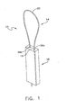
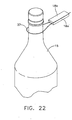
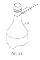
- FIGS. 1-14 and 18-23 A first embodiment of an anti-theft security tag 10 including an electronic article surveillance marker 12 for attachment to an article, such as a watch band 13, bottle 15, or other article is illustrated in FIGS. 1-14 and 18-23 .
- article refers to any type or style of consumer product.
- crimp or “crimped” is used in a conventional manner to mean pressing, squeezing, pinching, biting or the like into the member to be secured.
- watch refers to any style or type of watch which may be worn by a user.
- the present invention is not limited to use with watches, or bottles, and may be used with any of a variety of articles as would be known to those of skill in the art.
- the tag 10 of the present embodiment includes an engagement member 14 for securing the tag to the article, and a housing 16. Disposed within the housing is an internal crimping member 26 which, in the present embodiment is a self-crimping member as described in greater detail below.
- the housing also supports an electronic article surveillance (EAS) marker 12.
- EAS electronic article surveillance
- the housing 16 preferably includes a base 18a and a cover 18b.
- the base may have a front wall 19a, side walls 19b and 19c, a bottom wall 19d and a top wall 19e, the walls bounding an interior cavity 20 of the base.
- the top wall 19e may include a pair of indents 42 which, when the base 18a is engaged with the cover 18b mate with corresponding indents 44 to form a pair of openings 30a, 30b sized to receive a first end 22a and a free second end 22b, respectively, of the engagement member 14,
- the openings 30a, 30b preferably provide access to a pair of channels 21a, 21b disposed within the housing.
- the cover 18b is sized to fit over the base 18a and is secured there to during use.
- the cover 18b includes tabs 15 which are sized to fit within corresponding openings formed in the base.
- the base 18a and the cover 18b also preferably form an exit opening 23 when secured together in the present embodiment.
- EAS marker 12 may be supported within the housing, for example, on an inner surface of the cover 18b, such that it is hidden within housing 16 once assembled. Alternatively, other types of housings may be utilized, as would be known to those of skill in the art.
- the engagement member 14 may take any of a variety of forms, suitable for engagement with an article, and preferably includes a line 24, and one or more crimping members 26a-d for retaining the free or second end 22b of the line within the housing during use, as described in greater detail below.
- the line may preferably be made of wire (coated or non-coated), nylon or other semi-rigid monofilament lines, or other plastic member which is sufficiently strong so as to withstand tampering.
- the line is able to withstand about 40 to about 50 lbs of pressure before beginning to fail, although lines being able to withstand any of a variety of pressures may be utilized, as desired for the particular application.
- the line has a generally continuous outer surface which is crimped when inserted into the crimping members 26a-26d.
- a reinforcing member or end cap 17 may be secured to all or part of the line, as shown in FIGS. 18-20 , and described in greater detail below.
- the crimping member is internally disposed within the housing and is self-crimping such that it automatically engages and crimps the line upon insertion of the line within the crimping member, without additional manual crimping. In this manner, the line is prevented from being withdrawn as soon as it engages the crimping member.
- the crimping member may take any of a variety of forms, provided that it engages the line so as to crimp it to deter removal of the line from engagement with the crimping member. In the present embodiment, a plurality of washer or disc shaped crimping members 26a-26d are illustrated.
- Each crimping member preferably includes an annular ring 27 and a plurality of inwardly extending teeth or fingers 29 ( FIGS. 6-7 ) which crimp the line upon engagement and which may preferably flex during insertion of the line as described in greater detail below.
- the discs operate to automatically crimp the second end of the line 22b when it is inserted within each of the discs. In this manner, a separate crimping step is avoided.
- the teeth or fingers 29 may each have a generally triangular shape with pointed end 29a to engage and crimp the line, although other shapes may be utilized as would be known to those of skill in the art.
- the crimping members 26a-26d are each preferably supported within the channel 21b so that they are stationary longitudinally within the channel.
- the crimping members are supported within the channel by a plurality of shelves, or ledges 29b, as best shown in FIG. 9 , such that they are free to rotate within the shelves or ledges, but remain positioned at a predetermined longitudinal distance within the channel.
- the crimping members are preferably supported in alignment with each other, but may be selectively positioned along the length of the channel, as desired.
- the crimping members are illustrated as being supported on successive ledges, empty ledges may be disposed between the crimping members.
- the crimping members can be supported anywhere along the length of the channel, at the top, bottom or mid section, or a combination there of.
- the crimping members may be otherwise supported within the channel, as would be known to those of skill in the art.
- the center 31 of the crimping members are aligned with the opening 30b into the channel 21b.
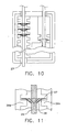
- the flexible fingers 29 engage and crimp the line 24 ( FIG. 10 ).
- the first end 22a is also secured within the housing, for example within channel 21 a.
- a sleeve 26e is supported on ledge 29a and is used to secure the first end 22a within channel 21a.
- first end be secured within the housing so that it may not be tampered with by a consumer.
- first end may be otherwise supported on or within the housing, as would be known to those of skill in the art.
- disc shaped crimping members are shown, any number and shape crimping members may be utilized, as desired.
- FIGS. 12-14 exemplary alternate embodiments of the internally disposed crimping members are illustrated.
- FIGS. 12-14 illustrate a cylindrical or tubular crimping member 26, having a plurality of inwardly extending teeth or fingers 29, which operate in the same manner as discussed above with respect to the discs.
- the fingers 29 may be supported on annular ring 27, or within the body 35 of the tubular member, or both.
- FIGS. 15-17 illustrate leaf spring shaped crimping members 26 according to an example not being part of the invention. In this example, instead of a round crimping member having an aperture bounded by an annular ring, a pair of springs each including at least one crimping tooth or finger 29, are spaced opposite each within the body of the housing.
- the crimping teeth 29 again crimp the line in the manner discussed above with respect to the crimping discs and cylinder.
- alternate methods of supporting the crimping members may be utilized, as would be known to those of skill in the art.
- a reinforcing member or end cap 17 may be secured to all or part of the line, regardless of the type of crimping member utilized. In such a case, the end cap is considered to be part of the line, even if it is not a unitary member.
- the end cap when the end cap is inserted within the line and crimped ( FIG. 20 ), because it is secured to the line, the line likewise be prevented from removal from the crimping member.
- other types of crimping members may be utilized, provided that they crimp the line as it is claimed in claim 1.
- the insertion, or second end 22b is inserted about the article, for example a hole 34 in a watch band or around the neck of a bottle, and into opening 30b so as to form a loop 37 ( FIGS. 21-23 ).
- the second end 22b is then inserted into channel 21b and through center 31 in the at least one crimping member 26a-d disposed within channel 21b ( FIG. 10 ). Once disposed through the center 31 flexible fingers angle in a downward direction, i.e. toward exit opening 23, and engage the line 24.
- the pointed ends of the fingers engage the line such that the second end 22b of the line cannot be moved in the upward direction, toward opening 30b, but can only be moved in the opposite, downward direction.
- the second end 22b can pass entirely through the housing and out of opening 23.
- the size of loop 37 is adjustable by increasing the length of the line which exits the housing through opening 23.
- the line continues to be fed through the opening 40 until loop 37 reaches the desired size.
- the loop 37 can be made continually smaller, it cannot be made larger because the crimping members allow movement of the second end 22b in only the downward direction.
- the tail end 22b may be cut so that it is flush with respect to the bottom 19d of the base.
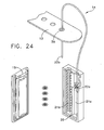
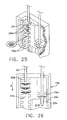
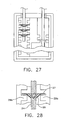
- FIGS. 24-29 an alternate embodiment of the anti-theft tag 10 is illustrated.
- This embodiment is identical to the embodiment of FIGS. 1-23 , except that the size of the loop is limited by the length of the line 24 that fits within the housing.
- exit opening 23 is eliminated such that the second end 22b is captured within the housing and does not exit the housing. In this manner, the second end 22b is tamper resistant as the consumer can not reach into the housing.
- the alternate embodiment may be used, for example, when the product to which the anti-theft tag is to be attached is know such that the length of the line 24 can be precut to size during manufacturing.
- the elimination of opening 23 limits the amount the loop 37 can be adjusted to the length of the housing.
- FIGS. 24-29 functions in the same manner as that of FIGS. 1-23 . Namely, the loop cannot be made larger once the second end is inserted within the crimping members, because the crimping members allow movement of the second end 22b in only the downward direction (i.e., into the housing).
- FIGS. 30-32 A third alternate embodiment of the anti-theft tag 10 is illustrated in FIGS. 30-32 .
- This embodiment is identical to the embodiment of FIGS. 24-29 , except an interior wall 25 is disposed within channel 21b adjacent a lowermost ledge 29b.
- the interior wall 25 acts as a stop to prevent further advancement of the second end 22b of the line 24 within channel 21b.
- the loop 37 which is formed exterior to the housing has a generally fixed size and is not adjustable in an appreciable manner.
- the size of the loop 37 is determined by the length of line utilized to form the loop and the depth at which the wall 25 is placed within the channel. In the present embodiment, any number of lines of varying lengths may be provided for use with the housing 16, depending upon the particular application. In this manner, the size of the loop is adjustable (by choosing a certain length of line) even if the second end 22b of the line is prevented from advancing within the channel 21b to effectuate adjustment of the loop 37.
- both the first and second ends 22a, 22b illustrate an anti-theft tag in which the first end 22a is fixed within the housing 16
- both the first and second ends 22a, 22b may be insertable within the housing, for example by a user, and thereafter engaged by a crimping member.
- both sets of channels 21a, 21b may be provided with corresponding ledges 29a, 29b each for supporting one or more crimping members 26.
- the first and second ends 22a, 22b could, thereafter be inserted into each of the corresponding channels until engaged by the crimping members.
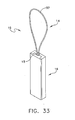
- a single channel for receiving both the first and second ends 22a, 22b could be provided, as shown in a fourth embodiment illustrated in FIGS. 33-37 .
- the fourth embodiment operates in the same manner as the preceding three embodiments, with the exception that the first end 22a is not supported within the housing in a fixed manner prior to receipt by a consumer.
- the first and second ends 22a, 22b are separate from the housing until both the first and second ends are inserted within the single channel, 21 that is provided.
- both ends of the line are inserted into a single hole 42, which may include a necked-down or funnel portion 43 that helps to guide both ends into the at least one crimping member 26.
- both the first and the second end are engaged by the fingers of the crimping members in order to secure the engagement member around the article and to the housing 16.
- a potential advantage to having the both the first and seconds ends supported in this manner is that because the discs 26 are free to rotate in a clockwise or counterclockwise direction as they sit on the ledges, the loop 37 would also be free to rotate. Thus, a consumer would find it harder to apply a twisting force in an effort to break the loop 37 then if one end were fixed and not rotatable (in which case it would be easier to apply a twisting force).
- tag 110 also includes an engagement member 114, and a housing 116 having a base 118a and a cover 118b.
- the base preferably includes a front wall 119a, side walls 119b and 119c, a bottom wall 119d and a top wall 119e, the walls bounding a cavity 120 formed in the base.
- the top wall 119e includes a pair of openings sized to receive a first end and a second end 122a, 122b, respectively, of the engagement member 114, the openings providing access to a pair of channels 121a, 121b disposed within the base.
- the at least one crimping member 126b is disposed in channel 121b and is preferably cylindrical and sized to loosely fit around the free, second end 122b of the engagement member prior to crimping.
- the first end 122a of the engagement member 114 is preferably received through an opening 130a in the top wall 118e of the housing 118a and into the crimping member 126a disposed in channel 121a.
- the crimping member 126a is preferably crimped by the manufacturer, and is sized larger than the opening 130a so that the first end is secured within the housing 118a when received by a retail establishment.
- the second end 122b of the line 1245 is preferably not crimped by the manufacturer so that the tag can be attached to the article at a later date, for example by a retailer.
- crimping member 126b is preferably held in place within channel 121b, in alignment with opening 130b and slot 133, which is sized to receive a crimping tool, as described in greater detail below.
- the crimping members 126a, 126b are pliant so that a crimping tool 128 engaging the members will force the members inward so as to crimp around the ends of the engagement member, as is known in the art.
- a conventional EAS marker 112 is preferably placed over the crimping members 126a, 126b and is supported within the cavity 120 of the housing 118a.
- interior walls 132 aid in supporting the EAS marker and also define the channels 121a, 121b.
- the cavity 120 and walls 132 are preferably dimensioned so that the EAS marker is approximately flush with the perimeter of the walls 119b-119e.
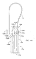
- connection of the tag to an article such as a watch band 113 is illustrated.
- the cover 118b is missing for purposes of illustration, in use the cover would be in place.
- the second end 112b is inserted about the article, here through a hole 134 in the watch band, and into opening 130b so as to form loop 137.
- the second end 122b is then inserted into crimping member 126 disposed within channel 121b.
- the crimping member is in alignment with opening 130b so that the second end is easily received within the member.
- a portion 132a of interior wall 132 prevents the second end 122b from being over-inserted and also aids in retaining the crimping member.
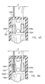
- Slot 133 is sized to receive a crimping tool 138, and is disposed through side wall 119b in alignment with the side of the crimping member 126b. After the second end 122b is inserted within the crimping member 126, the crimping tool is inserted through the slot 133 and engages the member 126b in order to force the member inwardly so as to crimp it around the second end of the engagement member. Because the member 126b is sized larger than the opening 130b, even in the crimped state, the second end 122b is secured within the housing. Once the second end is crimped within the housing, the size of loop 137 is fixed, and the anti-theft tag is securely attached to the article.
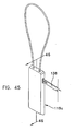
- FIGS. 47-52 another example not being part of the invention and including an adjustable engagement member is illustrated.
- the anti-theft tag 210 is identical to tag 110 described above with respect to the previous example, with the exception of channel 221b and the addition of a third opening 223 disposed through bottom wall 219d.
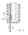
- channel 221b extends the length of the housing 218a, from opening 230b in top wall 219e down to opening 223 in bottom wall 219d.
- crimping member 226b may preferably be positioned adjacent the bottom wall 219d.
- the slot 233 for receiving the crimping tool is also positioned adjacent the bottom wall 219d, in alignment with crimping member 226b.
- the remaining elements of the anti-theft tag 210 are the same as in the previous example, including the positioning of the first end 222a and crimping member 226a within the housing 218a.
- the second end 222b By extending the channel the length of the housing 218a, from opening 230b in top wall 219e down to opening 223 in bottom wall 219d the second end 222b can pass entirely through the housing and out of opening 240 in bottom wall 219d ( FIG. 33 ). In this manner, the size loop 231 is adjustable by increasing or decreasing the length of the line which exits the housing through opening 240.
- the first end is first crimped, the EAS marker 212 is inserted and the cover 218b is attached, as described above with respect the first embodiment.
- the second end 222b is then passed through or around the article, through the first opening 230b, into channel 221b, through crimping member 226b and out of opening 223.
- the line continues to be fed through the opening 240 until loop 231 reaches the desired size.
- the member 226b is then crimped by applying the crimping tool 238 through slot 233, as described above to secure the tag and set the size of loop 231. After crimping, the portion of the line which extends from opening 223 may be cut, if desired.
- anti-theft tag described herein is capable of being readily assembled, while being tamper resistant after assembly, and may be attached to a variety of articles, as desired.
- the crimping member may have alternate shapes than those disclosed, the channels may or may not be provided, that the cover may take any of a variety of forms and be attached to the housing in any known manner, and the line may be formed of alternate materials, for example nylon or other types of plastic.
- the housing may be other shapes, for example circular, in which case there would be more or less walls, depending upon the particular shape, as would be known to those of skill in the art. Therefore, the above description should not be construed as limiting, but merely as exemplifications of a preferred embodiment. Those skilled in the art will envision other modifications within the scope of the invention as defined by the appended claims.
Landscapes
- Engineering & Computer Science (AREA)
- Physics & Mathematics (AREA)
- Computer Security & Cryptography (AREA)
- General Physics & Mathematics (AREA)
- Theoretical Computer Science (AREA)
- Automation & Control Theory (AREA)
- Electromagnetism (AREA)
- Burglar Alarm Systems (AREA)
Claims (15)
- Verstellbares Diebstahlsicherungsetikett (10) zum Anbringen an einem Artikel (13, 15), das Folgendes umfasst:eine Schnur (14, 24), die zum Befestigen des Etiketts (10) an dem Artikel (13, 15) aufgebaut und angeordnet ist, wobei die Schnur (14, 24) ein erstes Ende (22a) und ein zweites Ende (22b) hat;ein Gehäuse (16) mit einem Unterteil (18a), einem Oberteil (18b), wenigstens einer Öffnung (30b, 42), die so bemessen ist, dass sie das zweite Ende (22b) der Schnur (14, 24) aufnimmt, wobei das Gehäuse (16) so bemessen ist, dass es einen elektronischen Artikelüberwachungssensor (12) aufnimmt;wenigstens ein Klemmelement (26a-d), das innerhalb des Gehäuses (16) mit der wenigstens einen Öffnung (30b, 42) fluchtend gelagert ist, wobei das wenigstens eine Klemmelement (26a-d) ein Klemmelement (29) beinhaltet, das zum Festklemmen der Schnur (14, 24) nach dem Einführen der Schnur (14, 24) in das Gehäuse (16) und in Eingriff mit dem Klemmelement (29) aufgebaut und angeordnet ist; undwobei beim Festklemmen der Schnur (14, 24) eine Schlaufe außerhalb des Gehäuses (16) entsteht, wobei die Schlaufe von dem Klemmelement (29) auf einer maximalen Größe gehalten wird, das verhindert, dass der vom Klemmelement (29) festgeklemmte Abschnitt der Schnur (14, 24) aus dem Gehäuse (16) entfernt wird;dadurch gekennzeichnet, dass das wenigstens eine Klemmelement (26a-d) so konfiguriert und dimensioniert ist, dass es in dem Gehäuse gedreht werden kann.
- Diebstahlsicherungsetikett (10) nach Anspruch 1, wobei die Größe der Schlaufe durch Bewegen des zweiten Endes (22b) in Abwärtsrichtung weiter in das Gehäuse (16) verstellt werden kann, um die Schlaufe zu verkleinern, und wobei sich das zweite Ende (22b), wenn es mit dem wenigstens einen Klemmelement (26a-d) im Eingriff ist, nicht nach oben bewegen kann, so dass die Schlaufe nicht vergrößert werden kann.
- Diebstahlsicherungsetikett (10) nach Anspruch 1 oder 2, wobei das wenigstens eine Klemmelement (26a-d) aus den Elementen mit einer Ringform mit nach innen gerichteten Zähnen oder einer Röhrenform mit nach innen gerichteten Zähnen ausgewählt ist, wobei die Zähne (29) in jedem Fall so aufgebaut und angeordnet sind, dass sie die Schnur (24) nach dem Einführen des zweiten Endes (22b) in Eingriff mit den Zähnen (29) festklemmen.
- Diebstahlsicherungsetikett (10) nach Anspruch 1 oder 2, wobei das Klemmelement mehrere Zähne (29) aufweist, wobei die Zähne (29) nach innen zur Schnur (24) hin verlaufen und so aufgebaut und angeordnet sind, dass sie die Schnur (24) nach dem Einführen des zweiten Endes (22b) in Eingriff mit den Zähnen (29) festklemmen.
- Diebstahlsicherungsetikett (10) nach einem der vorherigen Ansprüche, wobei das Gehäuse (16) wenigstens einen Kanal (21b) aufweist, der so bemessen ist, dass er das zweite Ende (22b) des Eingriffselementes (14, 24) und das wenigstens eine Klemmelement (26a-d) aufnimmt.
- Diebstahlsicherungsetikett (10) nach Anspruch 5, wobei der wenigstens eine Kanal (21 b) wenigstens eine Rippe (29b) aufweist, die so aufgebaut und angeordnet ist, dass sie das wenigstens eine Klemmelement (26a-d) so trägt, dass das wenigstens eine Klemmelement (26a-d) mit der wenigstens einen Öffnung (30b, 42) in dem Gehäuse (16) fluchtet.
- Diebstahlsicherungsetikett (10) nach Anspruch 5, wobei der wenigstens eine Kanal einen ersten und einen zweiten Kanal beinhaltet, wobei der erste Kanal (21 a) so bemessen ist, dass er das erste Ende (22a) der Schnur aufnimmt, und der zweite Kanal (21b) so bemessen ist, dass er das zweite Ende (22b) der Schnur (24) aufnimmt.
- Diebstahlsicherungsetikett (10) nach Anspruch 5 oder 6, wobei der wenigstens eine Kanal (21b) von einer oberen Wand (19e) des Unterteils zu einer unteren Wand (19d) des Unterteils (18a) verläuft und wobei die untere Wand (19d) eine Austrittsöffnung (23) aufweist, die so bemessen ist, dass sie die Schnur (24) aufnimmt, wobei die Austrittsöffnung (23) mit dem wenigstens einen Kanal (21b) in Verbindung ist, so dass das zweite Ende (22b) in das Gehäuse (18) durch die wenigstens eine Öffnung (30b, 42) eingeführt werden kann und das Gehäuse (18a) durch die Austrittsöffnung (23) verlässt, so dass die Schlaufe selektiv verstellbar ist.
- Diebstahlsicherungsetikett (10) nach Anspruch 1, wobei das Oberteil (18b) ein Aufkleber mit klebstoffbeschichteter Rückseite ist.
- Diebstahlsicherungsetikett (10) nach Anspruch 1, wobei das wenigstens eine Klemmelement (26a-d) so bemessen ist, dass es sowohl das erste als auch das zweite Ende (22a, 22b) der Schnur (24) aufnimmt.
- Diebstahlsicherungsetikett (10) nach einem der vorherigen Ansprüche, wobei die Schnur (24) Elemente umfasst, die ausgewählt sind aus der Gruppe bestehend aus beschichtetem Draht, unbeschichtetem Draht, Nylon, Monofilschnur und Plastik.
- Diebstahlsicherungsetikett (10) nach einem der vorherigen Ansprüche, das ferner eine Endkappe (17) umfasst, die an dem zweiten Ende (22b) der Schnur (24) so befestigt ist, dass die Endkappe (17) nach dem Eingriff mit dem wenigstens einen Klemmelement (26a-d) festgeklemmt wird.
- Verfahren zum Anbringen eines Diebstahlsicherungsetiketts (10) an einem Artikel (13, 15), das die folgenden Schritte beinhaltet:Bereitstellen einer Schnur (14, 24), die zum Befestigen des Etiketts (10) an dem Artikel (13, 15) aufgebaut und angeordnet ist, wobei die Schnur (24) ein erstes Ende (22a) und ein zweites Ende (22b) aufweist;Bereitstellen eines Gehäuses (16) mit einem Unterteil (18a) mit wenigstens einer unteren Wand (19), die an einen inneren Hohlraum (20) angrenzt, wobei der Hohlraum (20) so bemessen ist, dass er einen elektronischen Artikelüberwachungssensor (12) aufnimmt, einem Deckel (18b) und wenigstens einer ersten Öffnung (30b, 42) in Verbindung mit dem Hohlraum (20);Befestigen des ersten Endes (22a) der Schnur (24) an dem Gehäuse (16);dadurch gekennzeichnet, dass das Verfahren ferner die folgenden Schritte beinhaltet:Bereitstellen von wenigstens einem Klemmelement (26a-d), das zum Aufnehmen der Schnur (24) darin aufgebaut und angeordnet ist, wobei das Klemmelement (26a-d) so konfiguriert und dimensioniert ist, dass es in dem Gehäuse gedreht werden kann und eine Bewegung der Schnur (24) dadurch in einer ersten Richtung in das Gehäuse (16) zulässt und eine Bewegung der Schnur (24) in einer zweiten Richtung aus dem Gehäuse (16) hinaus verhindert, wenn die Schnur (24) von dem wenigstens einen Klemmelement (26a-d) festgeklemmt wird;Lagern des wenigstens einen Klemmelementes (26a-d) im Hohlraum (20) des Gehäuses (16) so, dass es mit der ersten oder der zweiten Öffnung (30b, 42) fluchtet, und so, dass es beim Gebrauch in dem Gehäuse (16) in Längsrichtung fest bleibt.
- Verfahren nach Anspruch 14, das ferner den Schritt des Lagerns eines elektronischen Artikelüberwachungssensors (12) in dem Gehäuse beinhaltet.
- Verfahren zum Befestigen eines Diebstahlsicherungsetiketts (10) an einem Artikel (13, 15), das die folgenden Schritte beinhaltet:Bereitstellen eines Diebstahlsicherungsetiketts (10) nach einem der Ansprüche 1 bis 13;Befestigen eines ersten Endes (22a) der Schnur (24) an dem Gehäuse (16), wenn es nicht bereits so befestigt ist;Führen der Schnur (24) durch oder um den Artikel (13, 15);Einführen des zweiten Endes (22b) der Schnur (24) in die Einlassöffnung (30b, 42) des Gehäuses (16) in einem Ausmaß, das ausreicht, damit das Klemmelement (26a-d) die Schnur (24) festklemmen kann, so dass die Schnur nicht aus dem Gehäuse (16) herausgezogen werden kann.
Applications Claiming Priority (3)
| Application Number | Priority Date | Filing Date | Title |
|---|---|---|---|
| US10/696,483 US6933847B2 (en) | 2003-10-29 | 2003-10-29 | Anti-theft tag |
| US10/853,489 US7129841B2 (en) | 2003-10-29 | 2004-05-25 | Adjustable anti-theft tag |
| PCT/US2004/036094 WO2005043494A1 (en) | 2003-10-29 | 2004-10-29 | Anti-theft tag |
Publications (2)
| Publication Number | Publication Date |
|---|---|
| EP1678697A1 EP1678697A1 (de) | 2006-07-12 |
| EP1678697B1 true EP1678697B1 (de) | 2008-08-06 |
Family
ID=34556631
Family Applications (1)
| Application Number | Title | Priority Date | Filing Date |
|---|---|---|---|
| EP04796806A Expired - Lifetime EP1678697B1 (de) | 2003-10-29 | 2004-10-29 | Antidiebstahl-etikett |
Country Status (3)
| Country | Link |
|---|---|
| US (2) | US7227467B2 (de) |
| EP (1) | EP1678697B1 (de) |
| WO (1) | WO2005043494A1 (de) |
Families Citing this family (73)
| Publication number | Priority date | Publication date | Assignee | Title |
|---|---|---|---|---|
| US7518521B2 (en) * | 2003-10-29 | 2009-04-14 | Display Technologies, Inc. | Rotating anti-theft tag |
| US7474209B2 (en) * | 2005-01-14 | 2009-01-06 | Checkpoint Systems, Inc. | Cable alarm security device |
| US7363783B2 (en) * | 2005-09-26 | 2008-04-29 | B&G Plastics, Inc. | Rod and reel support with electronic marker device |
| US7412857B2 (en) * | 2005-09-26 | 2008-08-19 | B&G International, Inc. | Rod and reel support with electronic marker device |
| US20100327710A1 (en) * | 2006-08-02 | 2010-12-30 | B&G International, Inc. | Loop tag housing |
| USD566598S1 (en) * | 2006-09-27 | 2008-04-15 | Sayegh Adel O | Electronic article surveillance (EAS) tag with swiveling lanyard attachment |
| USD567128S1 (en) * | 2006-09-27 | 2008-04-22 | Sayegh Adel O | Electronic article surveillance (EAS) tag device with a lanyard |
| WO2008057740A2 (en) | 2006-10-19 | 2008-05-15 | Adel Odeh Sayegh | Security tag with engaging element |
| US7830264B2 (en) * | 2006-11-29 | 2010-11-09 | B&G International, Inc. | Removable electronic tag housing assembly |
| EP1970510A1 (de) * | 2007-03-13 | 2008-09-17 | MW Security AB | Sicherheitsvorrichtung |
| USD578030S1 (en) * | 2007-10-31 | 2008-10-07 | Wg Security Products | EAS tag with lanyard |
| US7978080B2 (en) | 2007-11-06 | 2011-07-12 | Bleckmann Frederick A | Pliable material loop tag |
| US8004406B2 (en) | 2007-11-06 | 2011-08-23 | Bleckmann Frederick A | Pliable material tag using a lanyard or a portion of a garment |
| WO2009076171A2 (en) * | 2007-12-07 | 2009-06-18 | Checkpoint Systems, Inc. | Pliable material tag using a lanyard or a portion of a garment |
| US8368543B2 (en) * | 2008-02-22 | 2013-02-05 | Xiao Hui Yang | EAS tag with wrapping tethers and cover |
| US8373566B2 (en) | 2008-02-22 | 2013-02-12 | Xiao Hui Yang | Security apparatus with tether |
| US8373565B2 (en) | 2008-02-22 | 2013-02-12 | Xiao Hui Yang | Security apparatus with conductive ribbons |
| USD606440S1 (en) * | 2008-04-25 | 2009-12-22 | Sayegh Adel O | Electronic article surveillance alarming tag having a lanyard |
| US8453937B2 (en) * | 2008-08-13 | 2013-06-04 | B&G International Inc. | Security hang tag with swivel head |
| USD599693S1 (en) | 2008-08-27 | 2009-09-08 | Sayegh Adel O | Theft deterrent tag having crossing lanyard for use with articles |
| US8466793B2 (en) | 2008-10-03 | 2013-06-18 | B&G Plastics, Inc. | Electronic tag holder for bottle neck |
| US8228200B2 (en) | 2008-10-03 | 2012-07-24 | B&G Plastics, Inc. | Electronic tag holder for bottle neck |
| US20100097219A1 (en) * | 2008-10-16 | 2010-04-22 | Sidnei Dal Gallo | Article with theft-deterring feature |
| US9396670B2 (en) * | 2008-12-03 | 2016-07-19 | B&G International, Inc. | Electronic tag holder for capped bottle neck |
| US8432286B2 (en) | 2008-12-03 | 2013-04-30 | B&G International, Inc. | Electronic tag holder for capped bottle neck |
| USD599242S1 (en) | 2009-02-23 | 2009-09-01 | Wg Security Products | Electronic article surveillance tag |
| US20100213263A1 (en) * | 2009-02-24 | 2010-08-26 | Advance Watch Company, Ltd., D/B/A, Geneva Watch Group | Electronic Article Surveillance Tag Assembly |
| US8547228B2 (en) | 2009-03-04 | 2013-10-01 | Checkpoint Systems, Inc. | Multi-attach reusable tag |
| US8344891B2 (en) * | 2009-03-04 | 2013-01-01 | Checkpoint Systems, Inc. | Security hard tag with attachment clip and method for attaching and detaching |
| US8581726B2 (en) * | 2009-03-04 | 2013-11-12 | Checkpoint Systems, Inc. | Two-stage universal security hard tag and method for attaching and detaching |
| US8547229B2 (en) | 2009-03-04 | 2013-10-01 | Checkpoint Systems, Inc. | Multi-attach disposable tag |
| CA2760079A1 (en) * | 2009-03-12 | 2010-09-16 | Checkpoint Systems, Inc. | Disposable cable lock and detachable alarm module |
| US8102268B2 (en) * | 2009-04-25 | 2012-01-24 | Union Tool & Mold Company | Machine washable ID label |
| US8049628B2 (en) * | 2009-04-25 | 2011-11-01 | Union Tool & Mold Company | Container-insertable anti-theft device |
| USD628924S1 (en) | 2009-05-05 | 2010-12-14 | Universal Surveillance Corporation | Theft deterrent tag having lanyards for use with articles |
| USD628923S1 (en) | 2009-05-05 | 2010-12-14 | Universal Surveillance Corporation | Electronic article surveillance device having lanyards for use with articles |
| AU2010202019B2 (en) | 2009-05-22 | 2015-08-20 | Stanley Works Israel Ltd | Object management system |
| US9847003B2 (en) | 2009-06-01 | 2017-12-19 | USS Technologies, LLC | Cable alarm tag |
| US8584958B2 (en) | 2011-03-25 | 2013-11-19 | Wg Security Products | EAS tag with twist prevention features |
| FR2951570B1 (fr) * | 2009-10-19 | 2012-06-29 | Thoonsen Trading | Dispositif antivol pour articles de vente |
| US9311797B2 (en) * | 2010-04-05 | 2016-04-12 | Wg Security Products | EAS tag for bottles |
| CN203347377U (zh) | 2010-04-30 | 2013-12-18 | 关卡系统公司 | 用于固定物体的安全组件 |
| CA2736825A1 (en) * | 2010-05-26 | 2011-11-26 | Christopher D. Gelowitz | Passive rfid chip reader antenna and embedded rfid chips |
| WO2012006428A1 (en) | 2010-07-09 | 2012-01-12 | B&G International Inc. | Tag for bottle neck having integral locking ring |
| US8730046B2 (en) | 2010-10-01 | 2014-05-20 | B&G Plastics, Inc. | EAS integrated faucet tag assembly |
| US20120205325A1 (en) * | 2011-02-08 | 2012-08-16 | DCI Marketing, Inc. (a Wisconsin corporation) | Product display system |
| US9336665B2 (en) | 2011-02-10 | 2016-05-10 | Wg Security Products | EAS tag with arming switch |
| US9076351B2 (en) | 2011-05-31 | 2015-07-07 | Koorosh Vafadari | Pallet and crate seal and method for securing a pallet or crate |
| US9390635B2 (en) * | 2011-05-31 | 2016-07-12 | Koorosh Vafadari | Pallet and crate seal and method for securing a pallet or crate |
| US8917180B2 (en) | 2011-06-01 | 2014-12-23 | Universal Surveillance Corporation | Theft deterrent tag |
| US8640514B2 (en) | 2011-06-22 | 2014-02-04 | The Stanley Works Israel Ltd. | Electronic and manual lock assembly |
| US8640513B2 (en) | 2011-06-22 | 2014-02-04 | The Stanley Works Israel Ltd. | Electronic and manual lock assembly |
| US8408472B2 (en) | 2011-08-05 | 2013-04-02 | Xiao Hui Yang | EAS tag with articulated body and attaching element |
| US20130098122A1 (en) * | 2011-10-19 | 2013-04-25 | Checkpoint Systems, Inc. | Cable lock with integral connected metal sheath |
| USD693257S1 (en) | 2011-12-08 | 2013-11-12 | Xiao Hui Yang | Electronic security apparatus with tether |
| US20140091781A1 (en) * | 2012-09-28 | 2014-04-03 | Hutchison International Ports Enterprises Limited | Security system |
| AP3462A (en) * | 2012-10-05 | 2015-11-30 | Racer Technology Pte Ltd | A security device |
| US9564033B2 (en) | 2013-02-20 | 2017-02-07 | Wg Security Products | One time use tag |
| US9324221B2 (en) | 2013-12-06 | 2016-04-26 | Wg Security Products | Anti-fraud tag |
| WO2014134292A1 (en) * | 2013-02-27 | 2014-09-04 | Michael Norman | Tag housing assembly for attachment to a bottle neck |
| US9095973B2 (en) * | 2013-03-15 | 2015-08-04 | Everlast Climbing Industries, Inc. | Bicycle service kits |
| MX373257B (es) | 2013-10-21 | 2020-07-01 | B&G Plastics Inc | Ensamble de alojamiento de etiqueta desprendible por consumidor para su fijacion a un cuello de botella. |
| EP3071769B1 (de) | 2013-11-18 | 2019-04-10 | InVue Security Products, Inc. | Hülle für konsumwaren. |
| DE102017107705A1 (de) * | 2017-04-10 | 2018-10-11 | Gemü Gebr. Müller Apparatebau Gmbh & Co. Kommanditgesellschaft | Vorrichtung zur Anordnung eines elektronischen Datenträgers an einer Komponente einer fluidtechnischen Anlage |
| US20180340357A1 (en) | 2017-05-25 | 2018-11-29 | Invue Security Products Inc. | Package wrap |
| USD890618S1 (en) | 2018-02-27 | 2020-07-21 | Invue Security Products Inc. | Cable wrap |
| CN112424844B (zh) | 2018-05-17 | 2023-05-09 | 关卡系统股份有限公司 | 双硬标签 |
| CN108665046B (zh) * | 2018-05-29 | 2021-04-02 | 京东方科技集团股份有限公司 | 一种防拆卸监测电路、电子标签、防盗系统及其防盗方法 |
| EP3803723A4 (de) | 2018-06-01 | 2022-03-09 | Stress Engineering Services, Inc. | Systeme und verfahren zur überwachung, verfolgung und rückverfolgung von logistik |
| USD880325S1 (en) * | 2018-12-26 | 2020-04-07 | Shanghai Adelante Co., Ltd | Electronic tag |
| US11773626B2 (en) * | 2022-02-15 | 2023-10-03 | Stress Engineering Services, Inc. | Systems and methods for facilitating logistics |
| US12482337B2 (en) * | 2023-05-04 | 2025-11-25 | Shenzhen Wins Electronic Technology Co., Ltd. | Method for assembling an RFID component to a locator in a cable lock |
| USD1039829S1 (en) * | 2023-11-14 | 2024-08-27 | Dongguan Kaishuo Electronics Technology Co., Ltd. | Keychain holder |
Family Cites Families (64)
| Publication number | Priority date | Publication date | Assignee | Title |
|---|---|---|---|---|
| US3065946A (en) | 1960-10-14 | 1962-11-27 | Lee Fashions Inc | Scarf support |
| US3253270A (en) | 1963-08-02 | 1966-05-24 | Downer Frank | Theft alarm for shoplift prevention |
| US3911534A (en) | 1974-10-30 | 1975-10-14 | I D Engineering Inc | Anti-theft fastening device |
| US3961431A (en) | 1975-09-22 | 1976-06-08 | Conversion Caddy Co. | Luggage tag |
| US4580319A (en) | 1980-07-14 | 1986-04-08 | Dennison Manufacturing Company | Bundling of objects |
| SE8205692D0 (sv) * | 1982-10-06 | 1982-10-06 | Arne F Jonsson | Tvers axeln genomstrommad stromningsmaskin med stellbara skovlar |
| US4506415A (en) | 1983-07-25 | 1985-03-26 | E. J. Brooks Company | Security seal and tag holder |
| US4588218A (en) | 1983-10-31 | 1986-05-13 | E. J. Brooks Company | Security seal |
| JPS61500368A (ja) | 1983-11-04 | 1986-03-06 | コチエツテイ,ゲリ− | 改良南京錠 |
| US4746909A (en) | 1986-09-02 | 1988-05-24 | Marcia Israel | Modular security system |
| US4875647A (en) | 1987-04-24 | 1989-10-24 | Daiwa Kasei Kogyo Kabushiki Kausha | Cable tie |
| US4962369A (en) * | 1989-02-09 | 1990-10-09 | Marcia Israel | Merchandise security system utilizing RF transmitter |
| US5099228A (en) | 1989-02-09 | 1992-03-24 | Marcia Israel | Electronic anti-theft merchandise tag having means for activating an alarm in response to an attempt to remove the tag from the merchandise |
| IT1230355B (it) | 1989-07-14 | 1991-10-18 | G T Di Giuseppe Tibiletti & C | Metodo per ottenere sigilli, in particolare per etichette di capi di abbigliamento, e sigillo secondo tale metodo. |
| US5120097A (en) * | 1990-07-30 | 1992-06-09 | The Rel Corporation | Security seal |
| US5079540A (en) | 1990-09-06 | 1992-01-07 | Sensormatic Electronics Corporation | Theft detection tag with adjustable loop |
| CH684134A5 (de) | 1991-12-16 | 1994-07-15 | Heinrich Sieber | An einen Gegenstand anbringbarer Sicherungsanhänger zur Signalisierung eines versuchten Diebstahls. |
| CH686593A5 (de) | 1992-01-10 | 1996-04-30 | Stoba Ag | Handschliessplombe. |
| US5570080A (en) | 1992-04-24 | 1996-10-29 | Toshio Inoue | Theft prevention tab device having alarm mechanism housed therein |
| ZA93554B (en) | 1992-08-26 | 1993-09-01 | R P L Ind Pty Ltd | Padlocks. |
| FR2702353B1 (fr) * | 1993-03-12 | 1995-06-02 | Patrick Lamy | Dispositif antivol pour lunettes. |
| FR2713379A1 (fr) | 1993-12-02 | 1995-06-09 | Wallet Claude | Dispositif de scellé, notamment pour conteneur ou article similaire. |
| US5524463A (en) | 1994-01-11 | 1996-06-11 | Sensormatic Electronics Corporation | Theft deterrent device to facilitate easy protection of large irregularly-shaped goods |
| US5513421A (en) | 1994-04-15 | 1996-05-07 | Thomas & Betts Corporation | Cable tie having an improved strap locking device |
| JP2733032B2 (ja) | 1995-03-10 | 1998-03-30 | アルプス電気株式会社 | 盗難監視装置用タグ及び盗難監視装置 |
| US5722266A (en) * | 1995-11-21 | 1998-03-03 | Alpha Enterprises, Inc. | Universal wrap security device |
| US5717382A (en) | 1996-03-15 | 1998-02-10 | Avery Dennison Corporation | Device for use in detecting the unauthorized removal of an article of commerce from a store or other business establishment |
| US5754108A (en) | 1996-05-06 | 1998-05-19 | Ungarsohn; Benjamin I. | Universal alarm system |
| IL119509A (en) * | 1996-10-28 | 2000-02-17 | Hi G Tek Ltd | Electronic tag |
| US5883576A (en) | 1998-01-14 | 1999-03-16 | De La Huerga; Carlos | Identification bracelet with electronics information |
| US5949336A (en) | 1997-02-03 | 1999-09-07 | Avery Dennison Corporation | Fastener assembly and method of making the same |
| NL1006433C1 (nl) | 1997-03-11 | 1998-09-14 | Mathieu Aarts | Samenstel voor het tijdelijk beveiligen en/of verpakken van een product, een dergelijke werkwijze en een dergelijke beveiliging. |
| US6692672B1 (en) * | 1997-06-02 | 2004-02-17 | Avery Dennison Corporation | EAS marker and method of manufacturing same |
| IL121250A (en) * | 1997-07-07 | 2000-01-31 | Hi G Tek Ltd | Tag system |
| US5969613A (en) | 1997-08-11 | 1999-10-19 | Alpha Enterprises, Inc. | Electronic article surveillance security device |
| IT1296683B1 (it) | 1997-11-06 | 1999-07-14 | Mainetti Tecnologie Spa | Sigillo antitaccheggio |
| US5977877A (en) | 1998-05-18 | 1999-11-02 | Instantel Inc. | Multiple conductor security tag |
| US5945909A (en) * | 1998-06-02 | 1999-08-31 | B&G Plastics, Inc. | Article identification and surveillance seal |
| ES2264819T3 (es) * | 1998-08-03 | 2007-01-16 | Hi-G-Tek Ltd | Cierre de bloqueo automatico. |
| US6052876A (en) | 1998-12-02 | 2000-04-25 | Sensormatic Electronics Corporation | Versatile attachment mechanism for theft deterrent tags |
| US6226839B1 (en) | 1999-01-05 | 2001-05-08 | Adel Odeh Sayegh | Securing means attachable to objects of varying size and shape |
| US6092401A (en) * | 1999-02-18 | 2000-07-25 | Alpha Enterprises, Inc. | Electronic article surveillance security device |
| US6446474B1 (en) | 1999-05-17 | 2002-09-10 | Secure Concepts, Ltd. | Key operable restraining device with spike engaging member |
| US6308539B1 (en) | 1999-07-09 | 2001-10-30 | B&G Plastics, Inc. | Article identification and surveillance tag |
| US6188320B1 (en) | 1999-07-29 | 2001-02-13 | B&G Plastics, Inc. | Article identification and surveillance tag having-article-engaging loop |
| IT1307379B1 (it) | 1999-08-06 | 2001-11-06 | Emilio Costa | Dispositivo antifurto per oggetti dotati di porzioni circondabili dafascette o simili. |
| US6255950B1 (en) | 1999-10-19 | 2001-07-03 | Sensormatic Electronics Corporation | Tack assembly for electronic article surveillance tags |
| DE19963130A1 (de) | 1999-12-24 | 2001-06-28 | Meto International Gmbh | Zu verschiedenen elektronischen Artikelüberwachungssystemen kompatible Sicherungseinrichtung und Verfahren zum Sichern von Artikeln |
| US6389853B1 (en) | 2000-01-13 | 2002-05-21 | Dell Usa, L.P. | Apparatus and method for deterring the theft of a computer |
| TW502267B (en) * | 2000-01-28 | 2002-09-11 | Matsushita Electric Industrial Co Ltd | Solid eleotrolytic capacitors and method for manufacturing the same |
| US6343819B1 (en) | 2000-02-24 | 2002-02-05 | Steven Shiozaki | Security tag |
| CA2305080A1 (en) | 2000-04-12 | 2001-10-12 | Cda Industries Inc. | Tamper-proof display |
| US6373390B1 (en) | 2000-08-08 | 2002-04-16 | Sensormatic Electronics Corporation | Electronic article surveillance tag having arcuate channel |
| US6311531B1 (en) | 2000-08-28 | 2001-11-06 | Emplast, Inc. | Security strap |
| US6523292B2 (en) * | 2000-12-14 | 2003-02-25 | Brenda L. Slavik | Clip card |
| US6433686B1 (en) | 2001-01-05 | 2002-08-13 | Display Technologies, Inc. | Security tag |
| US6624753B2 (en) | 2001-01-30 | 2003-09-23 | World Color, Inc. | One piece snap close anti-theft hang tag for merchandise |
| DE10109573C2 (de) | 2001-02-26 | 2003-02-06 | Jochen Bruening | Sicherungsvorrichtung |
| US20020154014A1 (en) | 2001-04-20 | 2002-10-24 | Steve Elston | One piece snap close anti-theft hang tag for merchandise |
| US6535130B2 (en) | 2001-04-25 | 2003-03-18 | Sensormatic Electronics Corporation | Security apparatus for electronic article surveillance tag |
| US6578394B2 (en) | 2001-09-06 | 2003-06-17 | Hewlett-Packard Development Company | Portable computer security device |
| US6567003B2 (en) | 2001-09-17 | 2003-05-20 | B&G Plastics, Inc. | Article identification and security tag |
| US6755055B2 (en) | 2002-02-26 | 2004-06-29 | Alpha Security Products, Inc. | Theft deterrent device |
| US20070029786A1 (en) * | 2005-07-20 | 2007-02-08 | Signat, Llc | Tamper indicating security device and method |
-
2004
- 2004-10-29 EP EP04796806A patent/EP1678697B1/de not_active Expired - Lifetime
- 2004-10-29 WO PCT/US2004/036094 patent/WO2005043494A1/en not_active Ceased
- 2004-10-29 US US10/977,058 patent/US7227467B2/en not_active Expired - Fee Related
-
2007
- 2007-04-16 US US11/787,278 patent/US7626501B2/en not_active Expired - Fee Related
Also Published As
| Publication number | Publication date |
|---|---|
| EP1678697A1 (de) | 2006-07-12 |
| WO2005043494A1 (en) | 2005-05-12 |
| US20050128089A1 (en) | 2005-06-16 |
| US7227467B2 (en) | 2007-06-05 |
| US20070285243A1 (en) | 2007-12-13 |
| US7626501B2 (en) | 2009-12-01 |
Similar Documents
| Publication | Publication Date | Title |
|---|---|---|
| US7626501B2 (en) | Anti-theft tag | |
| US7518521B2 (en) | Rotating anti-theft tag | |
| US7129841B2 (en) | Adjustable anti-theft tag | |
| US7183914B2 (en) | Hang tag with swivel attachment | |
| US9144274B2 (en) | Anti-theft ring assembly and method of using the same | |
| US8341985B2 (en) | Security device for ring products | |
| EP2084685B1 (de) | Sicherheitsetikett mit eingriffselement | |
| EP2590865B1 (de) | Markierung für flaschenhals mit integriertem verschlussring | |
| US6092656A (en) | Wrench socket holder with locking member | |
| US20070186597A1 (en) | Zipper tag housing | |
| US8466793B2 (en) | Electronic tag holder for bottle neck | |
| US7595733B2 (en) | Lockable pinless EAS tag with lanyard | |
| US7808390B2 (en) | Security tag having a swiveling engagement | |
| US20020174695A1 (en) | Theft deterrent tag | |
| US20060201836A1 (en) | Specialty product hang tag | |
| EP0692596B1 (de) | Diebstahl abschreckende Vorrichtung für Diebstahl gefährdete Artikel | |
| CA2304666C (en) | Self-lockable loop fastener | |
| JP2011511993A (ja) | 商品セキュリティタグ用の調節可能に拘束する適応可能な挿入部および挿入方法 | |
| US7714721B1 (en) | Anti-theft ring tag | |
| US20070012772A1 (en) | Plastic case for an EAS tag | |
| EP0921513B1 (de) | Siegel | |
| EP2344714B1 (de) | Stiftlose sicherheitsvorrichtung | |
| US8049628B2 (en) | Container-insertable anti-theft device | |
| WO2008154002A1 (en) | Theft deterrent device with integral lanyard attachment means | |
| US20060191801A1 (en) | Pilfer-resistant arrangements for watch and jewelry boxes |
Legal Events
| Date | Code | Title | Description |
|---|---|---|---|
| PUAI | Public reference made under article 153(3) epc to a published international application that has entered the european phase |
Free format text: ORIGINAL CODE: 0009012 |
|
| 17P | Request for examination filed |
Effective date: 20060428 |
|
| AK | Designated contracting states |
Kind code of ref document: A1 Designated state(s): AT BE BG CH CY CZ DE DK EE ES FI FR GB GR HU IE IT LI LU MC NL PL PT RO SE SI SK TR |
|
| 17Q | First examination report despatched |
Effective date: 20060731 |
|
| DAX | Request for extension of the european patent (deleted) | ||
| R17C | First examination report despatched (corrected) |
Effective date: 20070704 |
|
| GRAP | Despatch of communication of intention to grant a patent |
Free format text: ORIGINAL CODE: EPIDOSNIGR1 |
|
| GRAS | Grant fee paid |
Free format text: ORIGINAL CODE: EPIDOSNIGR3 |
|
| GRAA | (expected) grant |
Free format text: ORIGINAL CODE: 0009210 |
|
| AK | Designated contracting states |
Kind code of ref document: B1 Designated state(s): AT BE BG CH CY CZ DE DK EE ES FI FR GB GR HU IE IT LI LU MC NL PL PT RO SE SI SK TR |
|
| REG | Reference to a national code |
Ref country code: GB Ref legal event code: FG4D |
|
| REG | Reference to a national code |
Ref country code: CH Ref legal event code: EP |
|
| REG | Reference to a national code |
Ref country code: IE Ref legal event code: FG4D |
|
| REF | Corresponds to: |
Ref document number: 602004015631 Country of ref document: DE Date of ref document: 20080918 Kind code of ref document: P |
|
| PG25 | Lapsed in a contracting state [announced via postgrant information from national office to epo] |
Ref country code: NL Free format text: LAPSE BECAUSE OF FAILURE TO SUBMIT A TRANSLATION OF THE DESCRIPTION OR TO PAY THE FEE WITHIN THE PRESCRIBED TIME-LIMIT Effective date: 20080806 Ref country code: ES Free format text: LAPSE BECAUSE OF FAILURE TO SUBMIT A TRANSLATION OF THE DESCRIPTION OR TO PAY THE FEE WITHIN THE PRESCRIBED TIME-LIMIT Effective date: 20081117 |
|
| PG25 | Lapsed in a contracting state [announced via postgrant information from national office to epo] |
Ref country code: SI Free format text: LAPSE BECAUSE OF FAILURE TO SUBMIT A TRANSLATION OF THE DESCRIPTION OR TO PAY THE FEE WITHIN THE PRESCRIBED TIME-LIMIT Effective date: 20080806 Ref country code: FI Free format text: LAPSE BECAUSE OF FAILURE TO SUBMIT A TRANSLATION OF THE DESCRIPTION OR TO PAY THE FEE WITHIN THE PRESCRIBED TIME-LIMIT Effective date: 20080806 Ref country code: AT Free format text: LAPSE BECAUSE OF FAILURE TO SUBMIT A TRANSLATION OF THE DESCRIPTION OR TO PAY THE FEE WITHIN THE PRESCRIBED TIME-LIMIT Effective date: 20080806 |
|
| PG25 | Lapsed in a contracting state [announced via postgrant information from national office to epo] |
Ref country code: BE Free format text: LAPSE BECAUSE OF FAILURE TO SUBMIT A TRANSLATION OF THE DESCRIPTION OR TO PAY THE FEE WITHIN THE PRESCRIBED TIME-LIMIT Effective date: 20080806 |
|
| PG25 | Lapsed in a contracting state [announced via postgrant information from national office to epo] |
Ref country code: BG Free format text: LAPSE BECAUSE OF FAILURE TO SUBMIT A TRANSLATION OF THE DESCRIPTION OR TO PAY THE FEE WITHIN THE PRESCRIBED TIME-LIMIT Effective date: 20081106 Ref country code: DK Free format text: LAPSE BECAUSE OF FAILURE TO SUBMIT A TRANSLATION OF THE DESCRIPTION OR TO PAY THE FEE WITHIN THE PRESCRIBED TIME-LIMIT Effective date: 20080806 |
|
| PG25 | Lapsed in a contracting state [announced via postgrant information from national office to epo] |
Ref country code: PT Free format text: LAPSE BECAUSE OF FAILURE TO SUBMIT A TRANSLATION OF THE DESCRIPTION OR TO PAY THE FEE WITHIN THE PRESCRIBED TIME-LIMIT Effective date: 20090106 Ref country code: SK Free format text: LAPSE BECAUSE OF FAILURE TO SUBMIT A TRANSLATION OF THE DESCRIPTION OR TO PAY THE FEE WITHIN THE PRESCRIBED TIME-LIMIT Effective date: 20080806 Ref country code: CZ Free format text: LAPSE BECAUSE OF FAILURE TO SUBMIT A TRANSLATION OF THE DESCRIPTION OR TO PAY THE FEE WITHIN THE PRESCRIBED TIME-LIMIT Effective date: 20080806 Ref country code: RO Free format text: LAPSE BECAUSE OF FAILURE TO SUBMIT A TRANSLATION OF THE DESCRIPTION OR TO PAY THE FEE WITHIN THE PRESCRIBED TIME-LIMIT Effective date: 20080806 Ref country code: MC Free format text: LAPSE BECAUSE OF NON-PAYMENT OF DUE FEES Effective date: 20081031 |
|
| REG | Reference to a national code |
Ref country code: CH Ref legal event code: PL |
|
| PLBE | No opposition filed within time limit |
Free format text: ORIGINAL CODE: 0009261 |
|
| STAA | Information on the status of an ep patent application or granted ep patent |
Free format text: STATUS: NO OPPOSITION FILED WITHIN TIME LIMIT |
|
| 26N | No opposition filed |
Effective date: 20090507 |
|
| REG | Reference to a national code |
Ref country code: IE Ref legal event code: MM4A |
|
| REG | Reference to a national code |
Ref country code: FR Ref legal event code: ST Effective date: 20090630 |
|
| PG25 | Lapsed in a contracting state [announced via postgrant information from national office to epo] |
Ref country code: EE Free format text: LAPSE BECAUSE OF FAILURE TO SUBMIT A TRANSLATION OF THE DESCRIPTION OR TO PAY THE FEE WITHIN THE PRESCRIBED TIME-LIMIT Effective date: 20080806 |
|
| PG25 | Lapsed in a contracting state [announced via postgrant information from national office to epo] |
Ref country code: DE Free format text: LAPSE BECAUSE OF NON-PAYMENT OF DUE FEES Effective date: 20090501 Ref country code: IT Free format text: LAPSE BECAUSE OF FAILURE TO SUBMIT A TRANSLATION OF THE DESCRIPTION OR TO PAY THE FEE WITHIN THE PRESCRIBED TIME-LIMIT Effective date: 20080806 |
|
| PG25 | Lapsed in a contracting state [announced via postgrant information from national office to epo] |
Ref country code: LI Free format text: LAPSE BECAUSE OF NON-PAYMENT OF DUE FEES Effective date: 20081031 Ref country code: IE Free format text: LAPSE BECAUSE OF NON-PAYMENT OF DUE FEES Effective date: 20081029 Ref country code: FR Free format text: LAPSE BECAUSE OF NON-PAYMENT OF DUE FEES Effective date: 20081031 Ref country code: CH Free format text: LAPSE BECAUSE OF NON-PAYMENT OF DUE FEES Effective date: 20081031 |
|
| PG25 | Lapsed in a contracting state [announced via postgrant information from national office to epo] |
Ref country code: SE Free format text: LAPSE BECAUSE OF FAILURE TO SUBMIT A TRANSLATION OF THE DESCRIPTION OR TO PAY THE FEE WITHIN THE PRESCRIBED TIME-LIMIT Effective date: 20081106 |
|
| PG25 | Lapsed in a contracting state [announced via postgrant information from national office to epo] |
Ref country code: PL Free format text: LAPSE BECAUSE OF FAILURE TO SUBMIT A TRANSLATION OF THE DESCRIPTION OR TO PAY THE FEE WITHIN THE PRESCRIBED TIME-LIMIT Effective date: 20080806 |
|
| PG25 | Lapsed in a contracting state [announced via postgrant information from national office to epo] |
Ref country code: HU Free format text: LAPSE BECAUSE OF FAILURE TO SUBMIT A TRANSLATION OF THE DESCRIPTION OR TO PAY THE FEE WITHIN THE PRESCRIBED TIME-LIMIT Effective date: 20090207 Ref country code: CY Free format text: LAPSE BECAUSE OF FAILURE TO SUBMIT A TRANSLATION OF THE DESCRIPTION OR TO PAY THE FEE WITHIN THE PRESCRIBED TIME-LIMIT Effective date: 20080806 Ref country code: LU Free format text: LAPSE BECAUSE OF NON-PAYMENT OF DUE FEES Effective date: 20081029 |
|
| PG25 | Lapsed in a contracting state [announced via postgrant information from national office to epo] |
Ref country code: TR Free format text: LAPSE BECAUSE OF FAILURE TO SUBMIT A TRANSLATION OF THE DESCRIPTION OR TO PAY THE FEE WITHIN THE PRESCRIBED TIME-LIMIT Effective date: 20080806 |
|
| PG25 | Lapsed in a contracting state [announced via postgrant information from national office to epo] |
Ref country code: GR Free format text: LAPSE BECAUSE OF FAILURE TO SUBMIT A TRANSLATION OF THE DESCRIPTION OR TO PAY THE FEE WITHIN THE PRESCRIBED TIME-LIMIT Effective date: 20081107 |
|
| REG | Reference to a national code |
Ref country code: GB Ref legal event code: 732E Free format text: REGISTERED BETWEEN 20130808 AND 20130814 |
|
| PGFP | Annual fee paid to national office [announced via postgrant information from national office to epo] |
Ref country code: GB Payment date: 20131011 Year of fee payment: 10 |
|
| GBPC | Gb: european patent ceased through non-payment of renewal fee |
Effective date: 20141029 |
|
| PG25 | Lapsed in a contracting state [announced via postgrant information from national office to epo] |
Ref country code: GB Free format text: LAPSE BECAUSE OF NON-PAYMENT OF DUE FEES Effective date: 20141029 |