EP1679157B1 - Schleifteller mit Bearbeitungselement - Google Patents
Schleifteller mit Bearbeitungselement Download PDFInfo
- Publication number
- EP1679157B1 EP1679157B1 EP05112012A EP05112012A EP1679157B1 EP 1679157 B1 EP1679157 B1 EP 1679157B1 EP 05112012 A EP05112012 A EP 05112012A EP 05112012 A EP05112012 A EP 05112012A EP 1679157 B1 EP1679157 B1 EP 1679157B1
- Authority
- EP
- European Patent Office
- Prior art keywords
- machining
- plate
- lining
- machining plate
- recess
- Prior art date
- Legal status (The legal status is an assumption and is not a legal conclusion. Google has not performed a legal analysis and makes no representation as to the accuracy of the status listed.)
- Expired - Lifetime
Links
Images

Classifications
-
- B—PERFORMING OPERATIONS; TRANSPORTING
- B24—GRINDING; POLISHING
- B24B—MACHINES, DEVICES, OR PROCESSES FOR GRINDING OR POLISHING; DRESSING OR CONDITIONING OF ABRADING SURFACES; FEEDING OF GRINDING, POLISHING, OR LAPPING AGENTS
- B24B7/00—Machines or devices designed for grinding plane surfaces on work, including polishing plane glass surfaces; Accessories therefor
- B24B7/10—Single-purpose machines or devices
- B24B7/18—Single-purpose machines or devices for grinding floorings, walls, ceilings or the like
- B24B7/186—Single-purpose machines or devices for grinding floorings, walls, ceilings or the like with disc-type tools
-
- B—PERFORMING OPERATIONS; TRANSPORTING
- B24—GRINDING; POLISHING
- B24B—MACHINES, DEVICES, OR PROCESSES FOR GRINDING OR POLISHING; DRESSING OR CONDITIONING OF ABRADING SURFACES; FEEDING OF GRINDING, POLISHING, OR LAPPING AGENTS
- B24B7/00—Machines or devices designed for grinding plane surfaces on work, including polishing plane glass surfaces; Accessories therefor
- B24B7/10—Single-purpose machines or devices
- B24B7/18—Single-purpose machines or devices for grinding floorings, walls, ceilings or the like
-
- B—PERFORMING OPERATIONS; TRANSPORTING
- B24—GRINDING; POLISHING
- B24D—TOOLS FOR GRINDING, BUFFING OR SHARPENING
- B24D7/00—Bonded abrasive wheels, or wheels with inserted abrasive blocks, designed for acting otherwise than only by their periphery, e.g. by the front face; Bushings or mountings therefor
- B24D7/06—Bonded abrasive wheels, or wheels with inserted abrasive blocks, designed for acting otherwise than only by their periphery, e.g. by the front face; Bushings or mountings therefor with inserted abrasive blocks, e.g. segmental
- B24D7/066—Grinding blocks; their mountings or supports
Definitions
- the present invention relates to a machining plate which carries at least one machining element for the grinding, polishing and/or cutting of a floor surface.
- a machining appliance When machining, that is to say primarily grinding and polishing but also cutting floor surfaces with the aim of producing a plane, smooth surface, a machining appliance is commonly used which carries one or more machining element-carrying machining plates, which in contact with the floor surface are made to perform a movement in a plane parallel thereto, so that a machining, that is to say grinding, polishing or cutting action is produced on the floor surface.
- a disadvantage of known machining element-carrying machining plates is that the machining elements, especially when machining uneven surfaces, come to pieces, become detached from the machining plate or wear unevenly. In the event of an uneven pressure distribution over the machining plate, the machining plate and/or the floor surface may bum. This leads to the machining plate having to be replaced, but in some cases it also results in damage to the floor surface that is being machined.
- An object of the invention is therefore to provide an improved machining element-carrying machining plate, in which the risk of the machining elements coming to pieces, becoming detached or wearing unevenly is reduced.
- a further object is to provide a machining element-carrying machining plate which is easy to manufacture and which can be manufactured at low cost.
- a machining plate is therefore provided, having the features of claim 1.
- the term “elastic” signifies that the lining must have greater elasticity than the machining plate and the machining element, so that the springing action is basically produced entirely by the lining.
- Arranging the machining element in an elastically lined recess in the machining plate gives the machining element a capacity to perform a springing movement relative to the machining plate, which results in a damping of the shocks that occur when the grinding element strikes against projections, irregularities, edges etc. in the floor surface. It also affords damping of vibrations which occur as a result of the engagement of the machining element with the floor surface.
- the machining plate may be designed so that in use it is displaced in its main plane, basically parallel to a machined, basically plane surface.
- the machining plate may have a basically plane first surface, the recess forming a depression in said first surface.
- the machining plate may carry a plurality of machining elements.
- the recess may be defmed by an edge surface and a bottom surface, and the lining extends over at least a part of at least one of said edge surface and said bottom surface, so that at least a part of said edge surface and/or said bottom surface is lined.
- the lining extends over the entire said edge surface and/or the entire said bottom surface.
- the machining element may be frictionally secured in relation to the machining plate.
- the machining element is press-fitted in relation to the lining and/or the lining is press-fitted in relation to the recess.
- the machining element may also be secured in relation to the lining by positive interlocking.
- the machining element narrows in a direction outwards from the recess and at right angles to the main plane of the machining plate, and the machining element and the lining have interacting tapered surfaces for securing the machining element to the lining.
- the edge surface of the machining element has a groove and the inner surface of the lining has a collar designed for engagement in the groove for securing the machining element to the lining.
- the machining element may comprise a matrix filled with grinding abrasives/polishing agents.
- the machining element may comprise at least one cutting edge.
- grinding abrasives/polishing agents may be applied to the surface of the machining element remote from the machining plate.
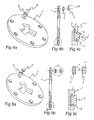
- Fig. 1 shows a machining plate 1, which carries six machining elements. One of the machining elements 3 is detached from the machining plate 1.
- the machining plate 1 comprises a basically plane, disc-shaped part with a thickness Y and a diameter D ( Fig. 2 ).
- the machining plate is circular, but it will be appreciated that it can also have other shapes, such as those shown in the aforementioned EP-1 321 233 and WO 2004/108352 , for example.
- the machining plate 1 may be made from metal or plastics, preferably thermoplastics, depending on the demands imposed by the intended application.
- the machining plate 1 may have fasteners for securing to a driven carrier (not shown), which produces a relative movement between the machining plate 1 and the floor surface.
- a driven carrier (not shown)
- One or more machining plates 1 may be secured on a driven carrier and one or more driven carriers may form part of the machining appliance.
- driven carriers may consist of driven planetary discs (not shown) on a driven sun disc (not shown).
- the machining plate 1 has a recess 4 for securing the machining element 3.
- the shape of the recess 4 is adapted to suit the machining element that is to be placed therein.
- the recess is cylindrical, that is to say it has a circular bottom surface 5 and the edges 6 thereof are defmed by a circumferential surface of a cylinder ( Fig. 3 ).
- the bottom surface of the recess may be of any shape, for example, elliptical, square, rhomboid, rectangular, etc. Any number of machining elements 3 may be arranged on the machining plate 1.
- the recess 4 is a bottom hole made in the machining plate 1.
- a lining 2 is arranged between the machining element 3 and the recess 4.
- An elastic material that is to say a material having a low modulus compared to the machining plate and the machining element, high elasticity or deformability and elastic behaviour, is selected as material in the lining.
- a rubber-elastic material which will withstand high temperatures such as fluororubber, perfluororubber or silicone rubber, is preferably chosen.
- fluororubber, perfluororubber or silicone rubber is preferably chosen.
- rubber-elastic material with inferior temperature stability may also be used.
- Thermoplastic elastomers such as urethane-based or amide-based TPE may also be used.
- Material for the lining 2 is selected on the basis of the forces and temperatures to which it is anticipated the machining element will be exposed.
- the lining may be produced in a number of different ways.
- the lining is moulded or injection moulded as a separate part, which is fitted into the recess before or at the same time that the machining element is being fitted therein.
- the recess 4 may be fully or partially lined. According to the embodiments described above the recess is largely fully lined. As an alternative it is possible to only partially line the recess.
- a suitable spring amplitude might be 1-2 mm, for example, but greater or lesser spring amplitudes can be achieved depending on how large the gap is made between the machining plate and the machining element and on which material is chosen for the lining.
- the machining element 3 may be secured to the lining 2 and the lining 2 to the recess 4 by means of a press-fit.
- the lining 2 and the machining element 3 may be formed so that they have interacting tapered surfaces 8, 10, which produce a positively interlocking and frictional connection between the machining element 3 and the lining 2.
- the recess 4 may be made with an undercut, so that it narrows in the direction of the machining plate 1 towards the surface 1a facing the floor surface.
- the machining element 3 may be made to narrow outwards, for example in the shape of a truncated cone.
- the size and shape of the recess 4, the lining 2 and the machining element 3 is be adapted so that the lining 2 and the machining element 3 can be pressed into the opening of the recess.
- the machining element may be provided with a peripheral groove 11 in the edge surface thereof.
- a corresponding lining may be provided with an inner salient groove or collar 12, so that when the machining element is inserted into the lining, the collar 12 meshes in the groove 11 and thereby produces a positively interlocking connection between the lining and the machining element.
- edge surfaces 8, 9 of the machining element and/or the lining are provided with one or more annular salient grooves, which are capable of acting together with one or more corresponding annular grooves in the lining 2 or the recess 4.
- fastening of the machining element 3 to the lining 2 and of the lining 2 to the recess 4 may be supplemented by adhesive means such as adhesive, double-sided tape etc.
- the machining element 3 may be formed in a number of different ways.
- the machining element may be formed as a matrix containing grinding abrasives.
- the matrix may be a thermoplastic or thermosetting plastic material, or a metal, for example.
- the grinding abrasive may be diamond or polycrystalline diamond (PCD), for example, or other grinding abrasive suited to the purpose.
- the grain size of the grinding abrasive is selected according to the required intensity of the grinding or polishing action.
- the machining element 3 is of the so-called single-layer type, that is to say provided with grinding abrasive which is affixed to the surface of the machining element, for example by means of a thermosetting plastic.
- the body of the machining element may comprise a matrix containing grinding abrasive or may comprise a backing block, having no grinding action, the function of which is to carry the grinding abrasive applied to the surface.
- a backing block may comprise a polymer or metal body, to the surface of which a thermosetting plastic material, for example phenol, melamine, urea or the like, has been applied, grinding abrasive such as diamond powder of selectable particle size having been distributed on the layer of thermoplastic material. If necessary, a further layer of thermoplastic material can then be applied on top of the layer of grinding abrasive.
- the machining element may be designed with a cutting edge, for example in a manner similar to the cutting edge-carrying part in EP 1 321 233 .
- machining elements with grinding, polishing or cutting action can be combined on one and the same machining plate.
- Machining element-carrying machining plates 1 as described above may be designed, according to what material is selected, for grinding, polishing or cutting of wooden floors, concrete floors, stone floors or similar floor surfaces.
Landscapes
- Engineering & Computer Science (AREA)
- Mechanical Engineering (AREA)
- Polishing Bodies And Polishing Tools (AREA)
Claims (14)
- Schleifteller (1), der zumindest ein Bearbeitungselement (3) zum Schleifen, Polieren und/oder Trennen einer Bodenfläche trägt, wobei das Bearbeitungselement (3) in einer Ausnehmung (4) des Schleiftellers (1) angeordnet ist, wobei die Ausnehmung (4) zumindest teilweise mit einer elastischen Auskleidung (2) versehen ist, so dass das Bearbeitungselement (3) elastisch relativ zum Schleifteller (1) fixiert ist, wobei die Ausnehmung (4) durch eine Kantenfläche (6) und eine Bodenfläche (5) definiert ist, und wobei sich die Auskleidung (2) über zumindest einen Teil der Kantenfläche (6) und der Bodenfläche (5) erstreckt,
dadurch gekennzeichnet, dass die Auskleidung (2) ein separates Teil darstellt, welches innerhalb der Ausnehmung (4) befestigt ist. - Schleifteller (1) nach Anspruch (1),
dadurch gekennzeichnet, dass der Schleifteller (1) derart gestaltet ist, dass dieser in Betrieb entlang der Hauptfläche verschiebbar ist, grundsätzlich parallel zu der zu bearbeitenden, hauptsächlich ebenen Fläche. - Schleifteller (1) nach Anspruch 1 oder 2,
dadurch gekennzeichnet, dass der Schleifteller (1) eine im Wesentlichen ebene erste Fläche (1a) und die Ausnehmung (4) aufweist, die eine Vertiefung in der besagten ersten Fläche (1a) bildet. - Schleifteller (1) nach einem der Ansprüche 1-3,
dadurch gekennzeichnet, dass der Schleifteller (1) eine Mehrzahl von Bearbeitungselementen (3) trägt. - Schleifteller (1) nach Anspruch 1,
dadurch gekennzeichnet, dass die Auskleidung (2) sich über die gesamte Kantenfläche (6) und/oder die gesamte Bodenfläche (5) erstreckt. - Schleifteller (1) nach einem der vorstehenden Ansprüche,
dadurch gekennzeichnet, dass das Bearbeitungselement (3) reibschlüssig gegenüber dem Schleifteller (1) befestigt ist. - Schleifteller (1) nach Anspruch 6,
dadurch gekennzeichnet, dass das Bearbeitungselement (3) in die Auskleidung (2) eingepresst ist und/oder die Auskleidung (2) eingepresst ist in die Ausnehmung (4). - Schleifteller (1) nach einem der vorstehenden Ansprüche,
dadurch gekennzeichnet, dass das Bearbeitungselement (3) bezüglich der Auskleidung (2) formschlüssig fixiert ist. - Schleifteller (1) nach Anspruch 8,
dadurch gekennzeichnet, dass sich das Bearbeitungselement (3) in der Richtung aus der Ausnehmung (4) heraus verengt und bezüglich der rechten Winkel zu der Hauptfläche des Schleiftellers (1), und dass das Bearbeitungselement (3) und die Auskleidung (2) eine zusammenwirkende konische Fläche (8, 10) zur Fixierung des Bearbeitungselements zur Auskleidung (2) aufweist. - Schleifteller (1) nach Anspruch 8,
dadurch gekennzeichnet, dass die Kantenfläche des Bearbeitungselements (3) eine Nut (11) aufweist, und dass die Innenfläche der Auskleidung (2) einen Bund (12) zum Verbinden innerhalb der Nut (11) zur Fixierung des Bearbeitungselements (3) bezüglich der Auskleidung (2) aufweist. - Schleifteller (1) nach einem der vorstehenden Ansprüche,
dadurch gekennzeichnet, dass das Bearbeitungselement (3) bezüglich der Auskleidung (2) und/oder die Auskleidung (2) bezüglich des Schleiftellers (1) durch Haftmittel, vorzugsweise Klebstoff, befestigt ist. - Schleifteller (1) nach einem der vorstehenden Ansprüche,
dadurch gekennzeichnet, dass das Bearbeitungselement (3) eine mit Schleifmittel oder Poliermittel gefülltes Bindemittel umfasst. - Schleifteller (1) nach einem der vorstehenden Ansprüche,
dadurch gekennzeichnet, dass das Bearbeitungselement (3) zumindest eine Schneidkante aufweist. - Schleifteller (1) nach einem der vorstehenden Ansprüche,
dadurch gekennzeichnet, dass Schleifmittel oder Poliermittel auf eine Fläche (7) des Bearbeitungselement (3) aufgebracht sind, abseitig des Schleiftellers (1).
Applications Claiming Priority (1)
| Application Number | Priority Date | Filing Date | Title |
|---|---|---|---|
| SE0500032A SE530209C2 (sv) | 2005-01-07 | 2005-01-07 | Bearbetningsplatta med bearbetningselement med separat foder |
Publications (2)
| Publication Number | Publication Date |
|---|---|
| EP1679157A1 EP1679157A1 (de) | 2006-07-12 |
| EP1679157B1 true EP1679157B1 (de) | 2008-02-20 |
Family
ID=34132508
Family Applications (1)
| Application Number | Title | Priority Date | Filing Date |
|---|---|---|---|
| EP05112012A Expired - Lifetime EP1679157B1 (de) | 2005-01-07 | 2005-12-13 | Schleifteller mit Bearbeitungselement |
Country Status (6)
| Country | Link |
|---|---|
| US (1) | US20080009232A1 (de) |
| EP (1) | EP1679157B1 (de) |
| AT (1) | ATE386613T1 (de) |
| DE (1) | DE602005004882T2 (de) |
| ES (1) | ES2300946T3 (de) |
| SE (1) | SE530209C2 (de) |
Cited By (2)
| Publication number | Priority date | Publication date | Assignee | Title |
|---|---|---|---|---|
| DE202008016862U1 (de) | 2008-12-19 | 2010-05-20 | Contec - Maschinenbau- & Entwicklungstechnik Gmbh | Schleifteller mit Werkzeugträgern für Schleifwerkzeuge |
| DE102008064081A1 (de) | 2008-12-19 | 2010-07-01 | Contec Maschinenbau & Entwicklungstechnik Gmbh | Schleifteller mit Werkzeugträgern für Schleifwerkzeuge |
Families Citing this family (23)
| Publication number | Priority date | Publication date | Assignee | Title |
|---|---|---|---|---|
| USD585466S1 (en) * | 2006-11-23 | 2009-01-27 | Rin Soon Park | Abrasive segment |
| EP1955809A1 (de) * | 2007-02-12 | 2008-08-13 | HTC Sweden AB | Werkzeug zum Bearbeiten von Stein- oder Betonböden |
| USD592229S1 (en) * | 2008-06-11 | 2009-05-12 | Rin-Soon Park | Grinding wheel |
| USD626977S1 (en) * | 2010-05-10 | 2010-11-09 | Popov Georgi M | Abrasive plate |
| USD626978S1 (en) * | 2010-07-16 | 2010-11-09 | Jae Hwan Huh | Grinding wheel |
| ITVR20100151A1 (it) * | 2010-07-23 | 2012-01-24 | Abrasivi Adria S R L | Utensile per la sagomatura superficiale di materiali lapidei |
| SE534947C2 (sv) * | 2010-09-03 | 2012-02-28 | Scanmaskin Sverige Ab | Flexibelt lagrad slipskiva |
| CN102528678B (zh) * | 2012-01-19 | 2014-05-14 | 泉州市易光石材工具有限公司 | 一种便于更换刀头的金刚石磨具 |
| DE202012009283U1 (de) * | 2012-09-27 | 2014-01-22 | Heger Gmbh European Diamond Tools | Grundscheibe für eine Topfschleifscheibe |
| CN104260003A (zh) * | 2014-09-28 | 2015-01-07 | 福州邦泰金研金刚石工具制造有限公司 | 一种即插即用式金刚石磨盘 |
| DE202015009462U1 (de) * | 2015-01-27 | 2017-09-18 | Polirtlak D.O.O. | Fahrbare Bodenschleifmaschine und Nachrüstsatz für einen Flügelglätter |
| WO2017096194A1 (en) * | 2015-12-02 | 2017-06-08 | Natural Chemistry, Inc. | Steering system for pool cleaners |
| JP6987434B2 (ja) * | 2017-06-19 | 2022-01-05 | 株式会社ディスコ | 研削ホイール |
| EP4257311A3 (de) | 2017-11-27 | 2023-12-27 | Dynatech Systems, Inc. | Frästrommelloses system zum materialabnehmen und verfahren zum herstellen eines frästrommellosen systems zum materialabnehmen |
| US10926375B2 (en) * | 2018-06-20 | 2021-02-23 | Gestion Anny Picard Inc. | Pressure-fit grinding pad assembly and method of construction |
| CN111136580B (zh) * | 2018-11-06 | 2021-12-14 | 丹阳华昌钻石工具制造有限公司 | 一种高硬度脆性材料加工用l形节块碗磨 |
| USD940767S1 (en) | 2020-01-24 | 2022-01-11 | Dynatech Systems, Inc. | Cutter head for grinding machines and the like |
| CN111531482A (zh) * | 2020-05-18 | 2020-08-14 | 林鑫森 | 一种电机驱动的地面研磨机的研磨盘 |
| USD978936S1 (en) * | 2020-06-25 | 2023-02-21 | Saint-Gobain Abrasives, Inc. | Floor edger sanding disc |
| USD978937S1 (en) * | 2020-06-25 | 2023-02-21 | Saint-Gobain Abrasives, Inc. | Floor edger sanding disc |
| USD978935S1 (en) * | 2020-06-25 | 2023-02-21 | Saint-Gobain Abrasives, Inc. | Floor edger sanding disc |
| USD978934S1 (en) * | 2020-06-25 | 2023-02-21 | Saint-Gobain Abrasives, Inc. | Floor edger sanding disc |
| JP2024535447A (ja) * | 2021-09-29 | 2024-09-30 | インテグリス・インコーポレーテッド | 両面パッドコンディショナー |
Family Cites Families (23)
| Publication number | Priority date | Publication date | Assignee | Title |
|---|---|---|---|---|
| BE375514A (de) * | ||||
| US2078120A (en) * | 1933-03-27 | 1937-04-20 | Norton Co | Grinding disk |
| US2453748A (en) * | 1947-04-05 | 1948-11-16 | Pittsburgh Plate Glass Co | Surfacing runner |
| US3121982A (en) * | 1960-08-25 | 1964-02-25 | Cons Diamond Dev Company Ltd | Grinding wheel with adjustable abrasive segments |
| US3464166A (en) * | 1967-05-23 | 1969-09-02 | Ferro Corp | Polishing plate |
| US3517466A (en) * | 1969-07-18 | 1970-06-30 | Ferro Corp | Stone polishing wheel for contoured surfaces |
| US3631635A (en) * | 1969-11-07 | 1972-01-04 | Kenneth W Vezner | Grinding and polishing machine |
| US3823516A (en) * | 1970-11-24 | 1974-07-16 | Norton Co | Motion imparting member incorporating holding means for nonwoven fibrous abrasive pads |
| US3738010A (en) * | 1972-08-07 | 1973-06-12 | Carder Ind Inc | Straight edge with non-slip inserts |
| US4631775A (en) * | 1985-10-15 | 1986-12-30 | Hako Minuteman, Inc. | High speed floor burnisher |
| DE3931277A1 (de) * | 1988-10-17 | 1990-04-19 | Zuschlagstoffe Natursteine Veb | Schleifteller zur bearbeitung von gestein oder aehnlichen werkstoffen und verfahren zu seiner herstellung |
| US5054245A (en) * | 1990-07-25 | 1991-10-08 | The Butcher Company | Combination of cleaning pads, cleaning pad mounting members and a base member for a rotary cleaning machine |
| GB9123502D0 (en) * | 1991-11-06 | 1992-01-02 | Black & Decker Inc | Sanding apparatus |
| AU654901B2 (en) * | 1992-03-16 | 1994-11-24 | De Beers Industrial Diamond Division (Proprietary) Limited | Polishing pad |
| US5514027A (en) * | 1994-04-22 | 1996-05-07 | Pearl Abrasive Co. | Sanding head for a sanding machine |
| JP2974047B2 (ja) * | 1995-03-15 | 1999-11-08 | 三和研磨工業株式会社 | 円形取付部を備えた砥石チップ嵌込式研磨板 |
| US5683143A (en) * | 1996-01-11 | 1997-11-04 | Pearl Abrasive Company | Abrasive surface treatment apparatus having removable blocks |
| US5779528A (en) * | 1996-07-12 | 1998-07-14 | Norton Company | Elastomeric mount for grinding wheel, and grinder |
| US6751822B2 (en) * | 1997-07-11 | 2004-06-22 | Pavelssebor Family Trust | Submerged surface pool cleaning device |
| US6755720B1 (en) * | 1999-07-15 | 2004-06-29 | Noritake Co., Limited | Vitrified bond tool and method of manufacturing the same |
| JP2001205560A (ja) * | 2000-01-28 | 2001-07-31 | Disco Abrasive Syst Ltd | 研削ホイール及び該研削ホイールの製造方法 |
| US6616517B2 (en) * | 2001-07-23 | 2003-09-09 | Onfloor Technologies, Llc | Wood floor sanding machine |
| US7033258B2 (en) * | 2003-09-05 | 2006-04-25 | Lite-Prep Surface Preparation Equipment, Llc | Floor resurfacing disks for rotary floor resurfacing machines |
-
2005
- 2005-01-07 SE SE0500032A patent/SE530209C2/sv not_active IP Right Cessation
- 2005-12-13 AT AT05112012T patent/ATE386613T1/de not_active IP Right Cessation
- 2005-12-13 ES ES05112012T patent/ES2300946T3/es not_active Expired - Lifetime
- 2005-12-13 EP EP05112012A patent/EP1679157B1/de not_active Expired - Lifetime
- 2005-12-13 DE DE602005004882T patent/DE602005004882T2/de not_active Expired - Lifetime
- 2005-12-22 US US11/316,796 patent/US20080009232A1/en not_active Abandoned
Cited By (2)
| Publication number | Priority date | Publication date | Assignee | Title |
|---|---|---|---|---|
| DE202008016862U1 (de) | 2008-12-19 | 2010-05-20 | Contec - Maschinenbau- & Entwicklungstechnik Gmbh | Schleifteller mit Werkzeugträgern für Schleifwerkzeuge |
| DE102008064081A1 (de) | 2008-12-19 | 2010-07-01 | Contec Maschinenbau & Entwicklungstechnik Gmbh | Schleifteller mit Werkzeugträgern für Schleifwerkzeuge |
Also Published As
| Publication number | Publication date |
|---|---|
| US20080009232A1 (en) | 2008-01-10 |
| ATE386613T1 (de) | 2008-03-15 |
| SE530209C2 (sv) | 2008-04-01 |
| SE0500032D0 (sv) | 2005-01-07 |
| SE0500032L (sv) | 2006-07-08 |
| DE602005004882D1 (de) | 2008-04-03 |
| EP1679157A1 (de) | 2006-07-12 |
| DE602005004882T2 (de) | 2009-02-12 |
| ES2300946T3 (es) | 2008-06-16 |
Similar Documents
| Publication | Publication Date | Title |
|---|---|---|
| EP1679157A1 (de) | Schleifteller mit Bearbeitungselement | |
| JP5114113B2 (ja) | ワークキャリア | |
| US7901272B2 (en) | Methods of bonding superabrasive particles in an organic matrix | |
| US5197249A (en) | Diamond tool with non-abrasive segments | |
| US6095910A (en) | Surface treatment article having a quick release fastener | |
| US20130225051A1 (en) | Abrasive pad assembly | |
| US20120037465A1 (en) | Braking device and method for manufacturing friction material | |
| US2581567A (en) | Buffer backing pad | |
| GB2107288A (en) | Impact-resistant wear plate | |
| TWI813551B (zh) | 具間隔物之墊修整器及具此墊修整器之晶圓化學機械平坦化系統 | |
| US20150017893A1 (en) | Disc for Abrading Flat Surfaces and Curved Surfaces | |
| EP0202241B1 (de) | Schleifpapierträger | |
| EP2903781A1 (de) | Halteanordnung für schleifwerkzeuge | |
| KR101783562B1 (ko) | 원터치홀더용 고정부를 장착한 연마디스크 | |
| JP2009515715A (ja) | カッティングディスク | |
| JP5972032B2 (ja) | 高効率精密加工用研磨工具及びその製法 | |
| KR102031741B1 (ko) | 연삭 휠 | |
| KR101711794B1 (ko) | 일체형의 고정부를 갖는 연마디스크 | |
| US5715115A (en) | Disk chucking mechanism | |
| DE50015654D1 (de) | Verbrauchbare rotationsscheibe zur bearbeitung von materialoberflächen mit einem grundkörper aus spritzgegossenem material, insbesondere kunststoff | |
| JP2005305603A (ja) | ハンディグラインダー用研磨ディスク | |
| AU2016421095A1 (en) | Roughing grinding tool | |
| KR20130127732A (ko) | 연마용 시트 | |
| KR102354813B1 (ko) | 변형 및 이탈 방지 효과가 우수한 원터치 타입의 그라인더용 연마 유닛 | |
| JP3153028U (ja) | コンディショニングディスク |
Legal Events
| Date | Code | Title | Description |
|---|---|---|---|
| PUAI | Public reference made under article 153(3) epc to a published international application that has entered the european phase |
Free format text: ORIGINAL CODE: 0009012 |
|
| AK | Designated contracting states |
Kind code of ref document: A1 Designated state(s): AT BE BG CH CY CZ DE DK EE ES FI FR GB GR HU IE IS IT LI LT LU LV MC NL PL PT RO SE SI SK TR |
|
| AX | Request for extension of the european patent |
Extension state: AL BA HR MK YU |
|
| 17P | Request for examination filed |
Effective date: 20060906 |
|
| 17Q | First examination report despatched |
Effective date: 20061009 |
|
| AKX | Designation fees paid |
Designated state(s): AT BE BG CH CY CZ DE DK EE ES FI FR GB GR HU IE IS IT LI LT LU LV MC NL PL PT RO SE SI SK TR |
|
| GRAP | Despatch of communication of intention to grant a patent |
Free format text: ORIGINAL CODE: EPIDOSNIGR1 |
|
| GRAS | Grant fee paid |
Free format text: ORIGINAL CODE: EPIDOSNIGR3 |
|
| GRAA | (expected) grant |
Free format text: ORIGINAL CODE: 0009210 |
|
| AK | Designated contracting states |
Kind code of ref document: B1 Designated state(s): AT BE BG CH CY CZ DE DK EE ES FI FR GB GR HU IE IS IT LI LT LU LV MC NL PL PT RO SE SI SK TR |
|
| REG | Reference to a national code |
Ref country code: GB Ref legal event code: FG4D |
|
| REG | Reference to a national code |
Ref country code: CH Ref legal event code: EP |
|
| REG | Reference to a national code |
Ref country code: IE Ref legal event code: FG4D |
|
| REF | Corresponds to: |
Ref document number: 602005004882 Country of ref document: DE Date of ref document: 20080403 Kind code of ref document: P |
|
| REG | Reference to a national code |
Ref country code: SE Ref legal event code: TRGR |
|
| REG | Reference to a national code |
Ref country code: ES Ref legal event code: FG2A Ref document number: 2300946 Country of ref document: ES Kind code of ref document: T3 |
|
| PG25 | Lapsed in a contracting state [announced via postgrant information from national office to epo] |
Ref country code: FI Free format text: LAPSE BECAUSE OF FAILURE TO SUBMIT A TRANSLATION OF THE DESCRIPTION OR TO PAY THE FEE WITHIN THE PRESCRIBED TIME-LIMIT Effective date: 20080220 Ref country code: IS Free format text: LAPSE BECAUSE OF FAILURE TO SUBMIT A TRANSLATION OF THE DESCRIPTION OR TO PAY THE FEE WITHIN THE PRESCRIBED TIME-LIMIT Effective date: 20080620 |
|
| PG25 | Lapsed in a contracting state [announced via postgrant information from national office to epo] |
Ref country code: AT Free format text: LAPSE BECAUSE OF FAILURE TO SUBMIT A TRANSLATION OF THE DESCRIPTION OR TO PAY THE FEE WITHIN THE PRESCRIBED TIME-LIMIT Effective date: 20080220 |
|
| PG25 | Lapsed in a contracting state [announced via postgrant information from national office to epo] |
Ref country code: BE Free format text: LAPSE BECAUSE OF FAILURE TO SUBMIT A TRANSLATION OF THE DESCRIPTION OR TO PAY THE FEE WITHIN THE PRESCRIBED TIME-LIMIT Effective date: 20080220 Ref country code: LV Free format text: LAPSE BECAUSE OF FAILURE TO SUBMIT A TRANSLATION OF THE DESCRIPTION OR TO PAY THE FEE WITHIN THE PRESCRIBED TIME-LIMIT Effective date: 20080220 Ref country code: PL Free format text: LAPSE BECAUSE OF FAILURE TO SUBMIT A TRANSLATION OF THE DESCRIPTION OR TO PAY THE FEE WITHIN THE PRESCRIBED TIME-LIMIT Effective date: 20080220 Ref country code: SI Free format text: LAPSE BECAUSE OF FAILURE TO SUBMIT A TRANSLATION OF THE DESCRIPTION OR TO PAY THE FEE WITHIN THE PRESCRIBED TIME-LIMIT Effective date: 20080220 |
|
| ET | Fr: translation filed | ||
| PG25 | Lapsed in a contracting state [announced via postgrant information from national office to epo] |
Ref country code: DK Free format text: LAPSE BECAUSE OF FAILURE TO SUBMIT A TRANSLATION OF THE DESCRIPTION OR TO PAY THE FEE WITHIN THE PRESCRIBED TIME-LIMIT Effective date: 20080220 Ref country code: CZ Free format text: LAPSE BECAUSE OF FAILURE TO SUBMIT A TRANSLATION OF THE DESCRIPTION OR TO PAY THE FEE WITHIN THE PRESCRIBED TIME-LIMIT Effective date: 20080220 Ref country code: PT Free format text: LAPSE BECAUSE OF FAILURE TO SUBMIT A TRANSLATION OF THE DESCRIPTION OR TO PAY THE FEE WITHIN THE PRESCRIBED TIME-LIMIT Effective date: 20080721 Ref country code: SK Free format text: LAPSE BECAUSE OF FAILURE TO SUBMIT A TRANSLATION OF THE DESCRIPTION OR TO PAY THE FEE WITHIN THE PRESCRIBED TIME-LIMIT Effective date: 20080220 |
|
| PG25 | Lapsed in a contracting state [announced via postgrant information from national office to epo] |
Ref country code: RO Free format text: LAPSE BECAUSE OF FAILURE TO SUBMIT A TRANSLATION OF THE DESCRIPTION OR TO PAY THE FEE WITHIN THE PRESCRIBED TIME-LIMIT Effective date: 20080220 |
|
| PLBE | No opposition filed within time limit |
Free format text: ORIGINAL CODE: 0009261 |
|
| STAA | Information on the status of an ep patent application or granted ep patent |
Free format text: STATUS: NO OPPOSITION FILED WITHIN TIME LIMIT |
|
| 26N | No opposition filed |
Effective date: 20081121 |
|
| PG25 | Lapsed in a contracting state [announced via postgrant information from national office to epo] |
Ref country code: LT Free format text: LAPSE BECAUSE OF FAILURE TO SUBMIT A TRANSLATION OF THE DESCRIPTION OR TO PAY THE FEE WITHIN THE PRESCRIBED TIME-LIMIT Effective date: 20080220 |
|
| PG25 | Lapsed in a contracting state [announced via postgrant information from national office to epo] |
Ref country code: BG Free format text: LAPSE BECAUSE OF FAILURE TO SUBMIT A TRANSLATION OF THE DESCRIPTION OR TO PAY THE FEE WITHIN THE PRESCRIBED TIME-LIMIT Effective date: 20080520 Ref country code: EE Free format text: LAPSE BECAUSE OF FAILURE TO SUBMIT A TRANSLATION OF THE DESCRIPTION OR TO PAY THE FEE WITHIN THE PRESCRIBED TIME-LIMIT Effective date: 20080220 |
|
| PG25 | Lapsed in a contracting state [announced via postgrant information from national office to epo] |
Ref country code: CY Free format text: LAPSE BECAUSE OF FAILURE TO SUBMIT A TRANSLATION OF THE DESCRIPTION OR TO PAY THE FEE WITHIN THE PRESCRIBED TIME-LIMIT Effective date: 20080220 Ref country code: MC Free format text: LAPSE BECAUSE OF NON-PAYMENT OF DUE FEES Effective date: 20081231 |
|
| PG25 | Lapsed in a contracting state [announced via postgrant information from national office to epo] |
Ref country code: IE Free format text: LAPSE BECAUSE OF NON-PAYMENT OF DUE FEES Effective date: 20081215 |
|
| PG25 | Lapsed in a contracting state [announced via postgrant information from national office to epo] |
Ref country code: LU Free format text: LAPSE BECAUSE OF NON-PAYMENT OF DUE FEES Effective date: 20081213 Ref country code: HU Free format text: LAPSE BECAUSE OF FAILURE TO SUBMIT A TRANSLATION OF THE DESCRIPTION OR TO PAY THE FEE WITHIN THE PRESCRIBED TIME-LIMIT Effective date: 20080821 |
|
| REG | Reference to a national code |
Ref country code: CH Ref legal event code: PL |
|
| PG25 | Lapsed in a contracting state [announced via postgrant information from national office to epo] |
Ref country code: TR Free format text: LAPSE BECAUSE OF FAILURE TO SUBMIT A TRANSLATION OF THE DESCRIPTION OR TO PAY THE FEE WITHIN THE PRESCRIBED TIME-LIMIT Effective date: 20080220 |
|
| PG25 | Lapsed in a contracting state [announced via postgrant information from national office to epo] |
Ref country code: CH Free format text: LAPSE BECAUSE OF NON-PAYMENT OF DUE FEES Effective date: 20091231 Ref country code: LI Free format text: LAPSE BECAUSE OF NON-PAYMENT OF DUE FEES Effective date: 20091231 Ref country code: GR Free format text: LAPSE BECAUSE OF FAILURE TO SUBMIT A TRANSLATION OF THE DESCRIPTION OR TO PAY THE FEE WITHIN THE PRESCRIBED TIME-LIMIT Effective date: 20080521 |
|
| PGFP | Annual fee paid to national office [announced via postgrant information from national office to epo] |
Ref country code: DE Payment date: 20121205 Year of fee payment: 8 |
|
| PGFP | Annual fee paid to national office [announced via postgrant information from national office to epo] |
Ref country code: SE Payment date: 20121217 Year of fee payment: 8 Ref country code: ES Payment date: 20121227 Year of fee payment: 8 Ref country code: GB Payment date: 20121212 Year of fee payment: 8 Ref country code: IT Payment date: 20121110 Year of fee payment: 8 |
|
| PGFP | Annual fee paid to national office [announced via postgrant information from national office to epo] |
Ref country code: FR Payment date: 20130107 Year of fee payment: 8 Ref country code: NL Payment date: 20121208 Year of fee payment: 8 |
|
| REG | Reference to a national code |
Ref country code: DE Ref legal event code: R119 Ref document number: 602005004882 Country of ref document: DE |
|
| REG | Reference to a national code |
Ref country code: NL Ref legal event code: V1 Effective date: 20140701 |
|
| REG | Reference to a national code |
Ref country code: SE Ref legal event code: EUG |
|
| GBPC | Gb: european patent ceased through non-payment of renewal fee |
Effective date: 20131213 |
|
| PG25 | Lapsed in a contracting state [announced via postgrant information from national office to epo] |
Ref country code: SE Free format text: LAPSE BECAUSE OF NON-PAYMENT OF DUE FEES Effective date: 20131214 |
|
| REG | Reference to a national code |
Ref country code: DE Ref legal event code: R119 Ref document number: 602005004882 Country of ref document: DE Effective date: 20140701 |
|
| REG | Reference to a national code |
Ref country code: FR Ref legal event code: ST Effective date: 20140829 |
|
| PG25 | Lapsed in a contracting state [announced via postgrant information from national office to epo] |
Ref country code: DE Free format text: LAPSE BECAUSE OF NON-PAYMENT OF DUE FEES Effective date: 20140701 Ref country code: NL Free format text: LAPSE BECAUSE OF NON-PAYMENT OF DUE FEES Effective date: 20140701 |
|
| PG25 | Lapsed in a contracting state [announced via postgrant information from national office to epo] |
Ref country code: GB Free format text: LAPSE BECAUSE OF NON-PAYMENT OF DUE FEES Effective date: 20131213 Ref country code: FR Free format text: LAPSE BECAUSE OF NON-PAYMENT OF DUE FEES Effective date: 20131231 |
|
| REG | Reference to a national code |
Ref country code: ES Ref legal event code: FD2A Effective date: 20150709 |
|
| PG25 | Lapsed in a contracting state [announced via postgrant information from national office to epo] |
Ref country code: ES Free format text: LAPSE BECAUSE OF NON-PAYMENT OF DUE FEES Effective date: 20131214 |
|
| PG25 | Lapsed in a contracting state [announced via postgrant information from national office to epo] |
Ref country code: IT Free format text: LAPSE BECAUSE OF NON-PAYMENT OF DUE FEES Effective date: 20131231 |
|
| PG25 | Lapsed in a contracting state [announced via postgrant information from national office to epo] |
Ref country code: IT Free format text: LAPSE BECAUSE OF NON-PAYMENT OF DUE FEES Effective date: 20131213 |