EP1679175A2 - Vorrichtung zum Vakuumkalibrieren extrudierter Profile - Google Patents
Vorrichtung zum Vakuumkalibrieren extrudierter Profile Download PDFInfo
- Publication number
- EP1679175A2 EP1679175A2 EP06000103A EP06000103A EP1679175A2 EP 1679175 A2 EP1679175 A2 EP 1679175A2 EP 06000103 A EP06000103 A EP 06000103A EP 06000103 A EP06000103 A EP 06000103A EP 1679175 A2 EP1679175 A2 EP 1679175A2
- Authority
- EP
- European Patent Office
- Prior art keywords
- vacuum
- linked
- connection
- air flow
- compressed air
- Prior art date
- Legal status (The legal status is an assumption and is not a legal conclusion. Google has not performed a legal analysis and makes no representation as to the accuracy of the status listed.)
- Withdrawn
Links
- 239000003638 chemical reducing agent Substances 0.000 claims description 6
- 239000004429 Calibre Substances 0.000 abstract description 2
- 239000007788 liquid Substances 0.000 description 3
- 239000002699 waste material Substances 0.000 description 3
- 238000001125 extrusion Methods 0.000 description 2
- 238000011144 upstream manufacturing Methods 0.000 description 2
- 230000007423 decrease Effects 0.000 description 1
- 230000000694 effects Effects 0.000 description 1
- 238000005265 energy consumption Methods 0.000 description 1
- 230000007613 environmental effect Effects 0.000 description 1
- 239000012530 fluid Substances 0.000 description 1
- 238000012423 maintenance Methods 0.000 description 1
- 239000000463 material Substances 0.000 description 1
- 239000012528 membrane Substances 0.000 description 1
- 238000000034 method Methods 0.000 description 1
- XLYOFNOQVPJJNP-UHFFFAOYSA-N water Substances O XLYOFNOQVPJJNP-UHFFFAOYSA-N 0.000 description 1
Images
Classifications
-
- B—PERFORMING OPERATIONS; TRANSPORTING
- B29—WORKING OF PLASTICS; WORKING OF SUBSTANCES IN A PLASTIC STATE IN GENERAL
- B29C—SHAPING OR JOINING OF PLASTICS; SHAPING OF MATERIAL IN A PLASTIC STATE, NOT OTHERWISE PROVIDED FOR; AFTER-TREATMENT OF THE SHAPED PRODUCTS, e.g. REPAIRING
- B29C48/00—Extrusion moulding, i.e. expressing the moulding material through a die or nozzle which imparts the desired form; Apparatus therefor
- B29C48/03—Extrusion moulding, i.e. expressing the moulding material through a die or nozzle which imparts the desired form; Apparatus therefor characterised by the shape of the extruded material at extrusion
- B29C48/09—Articles with cross-sections having partially or fully enclosed cavities, e.g. pipes or channels
-
- B—PERFORMING OPERATIONS; TRANSPORTING
- B29—WORKING OF PLASTICS; WORKING OF SUBSTANCES IN A PLASTIC STATE IN GENERAL
- B29C—SHAPING OR JOINING OF PLASTICS; SHAPING OF MATERIAL IN A PLASTIC STATE, NOT OTHERWISE PROVIDED FOR; AFTER-TREATMENT OF THE SHAPED PRODUCTS, e.g. REPAIRING
- B29C48/00—Extrusion moulding, i.e. expressing the moulding material through a die or nozzle which imparts the desired form; Apparatus therefor
- B29C48/25—Component parts, details or accessories; Auxiliary operations
- B29C48/88—Thermal treatment of the stream of extruded material, e.g. cooling
- B29C48/90—Thermal treatment of the stream of extruded material, e.g. cooling with calibration or sizing, i.e. combined with fixing or setting of the final dimensions of the extruded article
- B29C48/901—Thermal treatment of the stream of extruded material, e.g. cooling with calibration or sizing, i.e. combined with fixing or setting of the final dimensions of the extruded article of hollow bodies
- B29C48/903—Thermal treatment of the stream of extruded material, e.g. cooling with calibration or sizing, i.e. combined with fixing or setting of the final dimensions of the extruded article of hollow bodies externally
-
- B—PERFORMING OPERATIONS; TRANSPORTING
- B29—WORKING OF PLASTICS; WORKING OF SUBSTANCES IN A PLASTIC STATE IN GENERAL
- B29C—SHAPING OR JOINING OF PLASTICS; SHAPING OF MATERIAL IN A PLASTIC STATE, NOT OTHERWISE PROVIDED FOR; AFTER-TREATMENT OF THE SHAPED PRODUCTS, e.g. REPAIRING
- B29C48/00—Extrusion moulding, i.e. expressing the moulding material through a die or nozzle which imparts the desired form; Apparatus therefor
- B29C48/03—Extrusion moulding, i.e. expressing the moulding material through a die or nozzle which imparts the desired form; Apparatus therefor characterised by the shape of the extruded material at extrusion
- B29C48/12—Articles with an irregular circumference when viewed in cross-section, e.g. window profiles
-
- B—PERFORMING OPERATIONS; TRANSPORTING
- B29—WORKING OF PLASTICS; WORKING OF SUBSTANCES IN A PLASTIC STATE IN GENERAL
- B29C—SHAPING OR JOINING OF PLASTICS; SHAPING OF MATERIAL IN A PLASTIC STATE, NOT OTHERWISE PROVIDED FOR; AFTER-TREATMENT OF THE SHAPED PRODUCTS, e.g. REPAIRING
- B29C48/00—Extrusion moulding, i.e. expressing the moulding material through a die or nozzle which imparts the desired form; Apparatus therefor
- B29C48/25—Component parts, details or accessories; Auxiliary operations
- B29C48/88—Thermal treatment of the stream of extruded material, e.g. cooling
- B29C48/90—Thermal treatment of the stream of extruded material, e.g. cooling with calibration or sizing, i.e. combined with fixing or setting of the final dimensions of the extruded article
- B29C48/904—Thermal treatment of the stream of extruded material, e.g. cooling with calibration or sizing, i.e. combined with fixing or setting of the final dimensions of the extruded article using dry calibration, i.e. no quenching tank, e.g. with water spray for cooling or lubrication
Definitions
- the present invention relates to the field concerning the extrusion technique and particularly it refers to a vacuum calibrating device for extruded profiles.
- a drawback of such calibrating device consists in that the vacuum capacity in the normal liquid mechanical vacuum pump is almost constant and is not adjustable under 90% of the maximum value which is excessive in the most of the cases.
- An object of the present invention is to propose a vacuum calibrating device for the extruded profiles able to avoid the waste of energy by using the energy for the vacuum in an efficient manner.
- Another object is to propose a calibrating device having a small number of moving parts, reliable, with simple and rapid maintenance.
- the vacuum calibrating device for extruded profiles allows to obtain a wide variation range of vacuum capacity (from almost zero value until maximum capacity) and pneumatically operating.
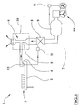
- the numeral 1 indicates the vacuum calibrating device for extruded profiles, of the present innovation.
- the calibrating device 1 comprises at least one vacuum manifold 2 to feed a respective calibre 3.
- Said manifold 2 is also provided with a connection 4 for the vacuum and with water link, of know type and not showed.
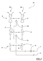
- connection 4 of the manifold 2 is connected by means of a non collapsible type duct, with a vacuum source 16 comprising a set of Venturi tubes 6, each of them being provided with a respective narrow passage 5.
- the linkage of the Venturi tubes 6 of the vacuum source 16 to the compressed air source 7 is carried out by means of a pressure-tight duct comprising an adjustable pressure reducer 8 fit to regulate the vacuum of the manifold 2 varying the air flow speed along the narrow passages 5 of the main ducts of the Venturi tubes 6 and in which the vacuum is generated.
- the device 1 includes one or more sets of Venturi tubes 20, in series pneumatically connected to be passed through by the same air flow produced by the source 7 and having the respective narrow passages 5 linked to the connection 4.
- the Venturi tubes sets are in number of two, but the present invention provides that the device can comprise only one or more than two of said sets depending on the number and requirements of the calibres.
- the section surface of a narrow passages 5 of a Venturi tube 6 of each set is bigger than the section surface of the Venturi tube 6 that precedes it in respect to the direction of the air flow passed through it.
- the narrow passages 5 of the Venturi tubes downstream the first one in respect to the air flow are linked to the connection 4 of the vacuum manifold 2 by means of respective check valves 21, for example of membrane type, fit to avoid the air exit from the narrow passages 5 toward the manifold in some operation conditions.
- the first narrow passage 5, upstream of the others respect to the air flow, is directly linked to the connection 4 of the vacuum manifold 2 without check valve, since it is able to maintain an sufficient depression in any operation condition.
- the invention provides that the device can be equipped, downstream of the tubes 6, with a noise suppressor made of sound-absorb material and that it can comprise, upstream of the narrow passages, an air filter of the manifold.
- a noise suppressor made of sound-absorb material and that it can comprise, upstream of the narrow passages, an air filter of the manifold.
- Such suppressor and filter are of known type and not showed.
- Each Venturi tube can be constituted by a nozzle flowing into a depression room and slightly spaced apart from, and faced to, a mouthpiece of a duct for the air flow.
- Such duct in the last Venturi tube, allows the air outlet toward outside, and, in the remaining tubes, carry out the nozzle inlet for the successive Venturi tubes.
- the narrow passage 5 is carried out by the fluid dynamics effect between the nozzle and the mouthpiece of the duct of the same room in whose wall is carried out a connection opening of the narrow passage to the connection 4 of the vacuum manifold 2.
- the device can be arranged for the connection to anyone compressed air source 7, such as a pre-existing distribution lines for the compressed air or a source of the type comprising at least a tank 9 powered by a motor-driven compressor 10 as showed in figure 1.
- anyone compressed air source 7 such as a pre-existing distribution lines for the compressed air or a source of the type comprising at least a tank 9 powered by a motor-driven compressor 10 as showed in figure 1.
- Such motor-driven compressor 10 is controlled by a pressure switch 11 connected to the tank 9. In this manner the tank accumulates, excluded the waste of energy, the energy in form of compressed air provided by the motor-driven compressor. Said compressed air is available according to the necessities for the vacuum generation in a controllable manner by means of the adjustment drives of the reducer 8.
- the invention provides that the vacuum manifold 2, or the connection 4, comprises a vacuum sensor 12, for example of piezoelectric type, electrically connected to control means 13 to provide them a signal proportional to the pressure of the manifold.
- a vacuum sensor 12 for example of piezoelectric type
- the control means 13 command, by means of an electric link, the adjustable pressure reducer 8, of electric driven type, to feedback control the vacuum pressure value in the manifold 2, for example set on a respective control input mean of the control means 13.
- the operation of the device provides that the increase of air flow speed along the narrow passages causes, into these latter, a pressure reduction till values lower than the environmental values and depending from, according to the D. Bernoulli law, the geometric characteristics of the tubes and from the air flow capacity in the main duct of each set of Venturi tubes.
- Such depression is “transmitted" from the respective connection 4 to the manifold 2 in which generates a vacuum whose pressure is adjusted varying the air capacity by means of the adjustable pressure reducer 8 controlled by means of a manual action or in an automatic close loop manner by means of the control means 13.
- An advantage of the present invention is to provide a vacuum calibrating device for extruded profiles able to avoid energetic wastes using in efficient manner the energy needed for the vacuum.
Landscapes
- Engineering & Computer Science (AREA)
- Mechanical Engineering (AREA)
- Physics & Mathematics (AREA)
- Thermal Sciences (AREA)
- Compressors, Vaccum Pumps And Other Relevant Systems (AREA)
- Extrusion Moulding Of Plastics Or The Like (AREA)
Applications Claiming Priority (1)
| Application Number | Priority Date | Filing Date | Title |
|---|---|---|---|
| IT000005A ITBO20050005A1 (it) | 2005-01-07 | 2005-01-07 | Banco di calibrazione a vuoto per estrusi |
Publications (2)
| Publication Number | Publication Date |
|---|---|
| EP1679175A2 true EP1679175A2 (de) | 2006-07-12 |
| EP1679175A8 EP1679175A8 (de) | 2011-02-23 |
Family
ID=36177809
Family Applications (1)
| Application Number | Title | Priority Date | Filing Date |
|---|---|---|---|
| EP06000103A Withdrawn EP1679175A2 (de) | 2005-01-07 | 2006-01-04 | Vorrichtung zum Vakuumkalibrieren extrudierter Profile |
Country Status (2)
| Country | Link |
|---|---|
| EP (1) | EP1679175A2 (de) |
| IT (1) | ITBO20050005A1 (de) |
-
2005
- 2005-01-07 IT IT000005A patent/ITBO20050005A1/it unknown
-
2006
- 2006-01-04 EP EP06000103A patent/EP1679175A2/de not_active Withdrawn
Also Published As
| Publication number | Publication date |
|---|---|
| ITBO20050005A1 (it) | 2006-07-08 |
| EP1679175A8 (de) | 2011-02-23 |
Similar Documents
| Publication | Publication Date | Title |
|---|---|---|
| CN101225897B (zh) | 一种自动开闭的气力输送用助吹阀门 | |
| CN101163887B (zh) | 用于在停止期间控制变速压缩机的系统和方法 | |
| CN100545776C (zh) | 用于调节器的无大气排放的受压式导阀系统和方法 | |
| EP1978222A3 (de) | Partikeltrennvorrichtung und Ablagerungskontrollsystem | |
| EP1783048A3 (de) | Integriertes Regelventil für einen Verdichter zur Steuerung der Wärmezufuhr und des Pumpens | |
| EP1679175A2 (de) | Vorrichtung zum Vakuumkalibrieren extrudierter Profile | |
| JP6215765B2 (ja) | 圧縮装置 | |
| WO2005081348A3 (en) | Fuel cell system with variable coanda amplifiers for gas recirculation and system pressure regulation | |
| JP6420711B2 (ja) | 換気システム | |
| KR101235563B1 (ko) | 관로 압력을 이용한 체크 밸브 제어 장치 | |
| JPH06185499A (ja) | 真空発生装置 | |
| EP1201897A3 (de) | Steuereinheit und Verfahren zur Berechnung des Luftdurchflusses | |
| DK1364890T3 (da) | Indretning til pludselig afgivelse af trykluft | |
| CN116428519B (zh) | 一种微小气流控制的压力调节系统 | |
| JP6300624B2 (ja) | 圧縮装置 | |
| US8113228B2 (en) | Suction valve | |
| CA2449779C (en) | An air outlet unit for a large blower assembly | |
| CN105264198B (zh) | 发动机系统以及船舶 | |
| CN109623154B (zh) | 一种全自动气动螺旋送粉装置及其使用方法 | |
| JP7851777B2 (ja) | パーティクル検出装置 | |
| CN223280162U (zh) | 用于密相输送的气流传输系统 | |
| CN119593987A (zh) | 用于远距离环境的空气压缩机系统 | |
| JP4840973B2 (ja) | 逆浸透濃縮装置 | |
| CN110687938A (zh) | 一种液位控制系统及方法 | |
| CN209601633U (zh) | 气力调速装置 |
Legal Events
| Date | Code | Title | Description |
|---|---|---|---|
| PUAI | Public reference made under article 153(3) epc to a published international application that has entered the european phase |
Free format text: ORIGINAL CODE: 0009012 |
|
| AK | Designated contracting states |
Kind code of ref document: A2 Designated state(s): AT BE BG CH CY CZ DE DK EE ES FI FR GB GR HU IE IS IT LI LT LU LV MC NL PL PT RO SE SI SK TR |
|
| AX | Request for extension of the european patent |
Extension state: AL BA HR MK YU |
|
| STAA | Information on the status of an ep patent application or granted ep patent |
Free format text: STATUS: THE APPLICATION IS DEEMED TO BE WITHDRAWN |
|
| 18D | Application deemed to be withdrawn |
Effective date: 20110801 |