EP1679195A2 - Structure de montage pour un détecteur de liquide et reservoir de liquide - Google Patents
Structure de montage pour un détecteur de liquide et reservoir de liquide Download PDFInfo
- Publication number
- EP1679195A2 EP1679195A2 EP05027078A EP05027078A EP1679195A2 EP 1679195 A2 EP1679195 A2 EP 1679195A2 EP 05027078 A EP05027078 A EP 05027078A EP 05027078 A EP05027078 A EP 05027078A EP 1679195 A2 EP1679195 A2 EP 1679195A2
- Authority
- EP
- European Patent Office
- Prior art keywords
- sensor
- liquid
- cavity
- flow path
- path
- Prior art date
- Legal status (The legal status is an assumption and is not a legal conclusion. Google has not performed a legal analysis and makes no representation as to the accuracy of the status listed.)
- Granted
Links
- 239000007788 liquid Substances 0.000 title claims abstract description 585
- 238000011144 upstream manufacturing Methods 0.000 claims abstract description 138
- 238000001514 detection method Methods 0.000 claims abstract description 133
- 239000010410 layer Substances 0.000 claims description 52
- 238000007789 sealing Methods 0.000 claims description 48
- 238000003825 pressing Methods 0.000 claims description 45
- 239000002313 adhesive film Substances 0.000 claims description 38
- 229920005989 resin Polymers 0.000 claims description 14
- 239000011347 resin Substances 0.000 claims description 14
- 239000012790 adhesive layer Substances 0.000 claims description 13
- 229910052751 metal Inorganic materials 0.000 claims description 11
- 239000002184 metal Substances 0.000 claims description 11
- 238000007599 discharging Methods 0.000 claims description 9
- 239000000853 adhesive Substances 0.000 description 30
- 230000001070 adhesive effect Effects 0.000 description 30
- 230000007423 decrease Effects 0.000 description 30
- 238000004519 manufacturing process Methods 0.000 description 24
- 238000010586 diagram Methods 0.000 description 21
- 238000007639 printing Methods 0.000 description 21
- 230000002708 enhancing effect Effects 0.000 description 19
- 230000000694 effects Effects 0.000 description 18
- 239000000463 material Substances 0.000 description 16
- 239000010408 film Substances 0.000 description 13
- 238000000034 method Methods 0.000 description 12
- 238000004088 simulation Methods 0.000 description 10
- 239000000758 substrate Substances 0.000 description 10
- 229920001971 elastomer Polymers 0.000 description 9
- 230000008569 process Effects 0.000 description 9
- 230000035945 sensitivity Effects 0.000 description 7
- 229910052451 lead zirconate titanate Inorganic materials 0.000 description 6
- 230000002093 peripheral effect Effects 0.000 description 6
- 230000001965 increasing effect Effects 0.000 description 5
- 230000033001 locomotion Effects 0.000 description 5
- 230000005499 meniscus Effects 0.000 description 5
- PXHVJJICTQNCMI-UHFFFAOYSA-N Nickel Chemical compound [Ni] PXHVJJICTQNCMI-UHFFFAOYSA-N 0.000 description 4
- MCMNRKCIXSYSNV-UHFFFAOYSA-N Zirconium dioxide Chemical compound O=[Zr]=O MCMNRKCIXSYSNV-UHFFFAOYSA-N 0.000 description 4
- 230000006835 compression Effects 0.000 description 4
- 238000007906 compression Methods 0.000 description 4
- 239000013013 elastic material Substances 0.000 description 4
- 238000003780 insertion Methods 0.000 description 4
- 230000037431 insertion Effects 0.000 description 4
- 238000005728 strengthening Methods 0.000 description 4
- RTAQQCXQSZGOHL-UHFFFAOYSA-N Titanium Chemical compound [Ti] RTAQQCXQSZGOHL-UHFFFAOYSA-N 0.000 description 3
- 238000004458 analytical method Methods 0.000 description 3
- 239000012530 fluid Substances 0.000 description 3
- 239000002440 industrial waste Substances 0.000 description 3
- 238000007641 inkjet printing Methods 0.000 description 3
- 229910052746 lanthanum Inorganic materials 0.000 description 3
- FZLIPJUXYLNCLC-UHFFFAOYSA-N lanthanum atom Chemical compound [La] FZLIPJUXYLNCLC-UHFFFAOYSA-N 0.000 description 3
- HFGPZNIAWCZYJU-UHFFFAOYSA-N lead zirconate titanate Chemical compound [O-2].[O-2].[O-2].[O-2].[O-2].[Ti+4].[Zr+4].[Pb+2] HFGPZNIAWCZYJU-UHFFFAOYSA-N 0.000 description 3
- 238000007726 management method Methods 0.000 description 3
- 230000006641 stabilisation Effects 0.000 description 3
- 238000011105 stabilization Methods 0.000 description 3
- RYGMFSIKBFXOCR-UHFFFAOYSA-N Copper Chemical compound [Cu] RYGMFSIKBFXOCR-UHFFFAOYSA-N 0.000 description 2
- BQCADISMDOOEFD-UHFFFAOYSA-N Silver Chemical compound [Ag] BQCADISMDOOEFD-UHFFFAOYSA-N 0.000 description 2
- 229910052782 aluminium Inorganic materials 0.000 description 2
- XAGFODPZIPBFFR-UHFFFAOYSA-N aluminium Chemical compound [Al] XAGFODPZIPBFFR-UHFFFAOYSA-N 0.000 description 2
- PNEYBMLMFCGWSK-UHFFFAOYSA-N aluminium oxide Inorganic materials [O-2].[O-2].[O-2].[Al+3].[Al+3] PNEYBMLMFCGWSK-UHFFFAOYSA-N 0.000 description 2
- 230000008859 change Effects 0.000 description 2
- 229910052802 copper Inorganic materials 0.000 description 2
- 239000010949 copper Substances 0.000 description 2
- 238000013461 design Methods 0.000 description 2
- 230000006866 deterioration Effects 0.000 description 2
- 239000000806 elastomer Substances 0.000 description 2
- 230000005684 electric field Effects 0.000 description 2
- PCHJSUWPFVWCPO-UHFFFAOYSA-N gold Chemical compound [Au] PCHJSUWPFVWCPO-UHFFFAOYSA-N 0.000 description 2
- 229910052737 gold Inorganic materials 0.000 description 2
- 239000010931 gold Substances 0.000 description 2
- 230000009545 invasion Effects 0.000 description 2
- 239000004973 liquid crystal related substance Substances 0.000 description 2
- 239000007769 metal material Substances 0.000 description 2
- 229910052759 nickel Inorganic materials 0.000 description 2
- 238000012856 packing Methods 0.000 description 2
- 238000005192 partition Methods 0.000 description 2
- -1 platina Chemical compound 0.000 description 2
- 229920000642 polymer Polymers 0.000 description 2
- 230000009467 reduction Effects 0.000 description 2
- 230000001105 regulatory effect Effects 0.000 description 2
- 230000000630 rising effect Effects 0.000 description 2
- 229910052709 silver Inorganic materials 0.000 description 2
- 239000004332 silver Substances 0.000 description 2
- 238000003860 storage Methods 0.000 description 2
- 238000000018 DNA microarray Methods 0.000 description 1
- 241001481828 Glyptocephalus cynoglossus Species 0.000 description 1
- 230000004888 barrier function Effects 0.000 description 1
- 235000014121 butter Nutrition 0.000 description 1
- 239000003990 capacitor Substances 0.000 description 1
- 239000000919 ceramic Substances 0.000 description 1
- 238000004140 cleaning Methods 0.000 description 1
- 238000007796 conventional method Methods 0.000 description 1
- 230000007797 corrosion Effects 0.000 description 1
- 238000005260 corrosion Methods 0.000 description 1
- 239000013039 cover film Substances 0.000 description 1
- 230000003247 decreasing effect Effects 0.000 description 1
- 239000007772 electrode material Substances 0.000 description 1
- 238000012423 maintenance Methods 0.000 description 1
- 238000005259 measurement Methods 0.000 description 1
- 239000011368 organic material Substances 0.000 description 1
- 239000010970 precious metal Substances 0.000 description 1
- 238000005245 sintering Methods 0.000 description 1
- 229910001220 stainless steel Inorganic materials 0.000 description 1
- 239000010935 stainless steel Substances 0.000 description 1
- 229920003002 synthetic resin Polymers 0.000 description 1
- 239000000057 synthetic resin Substances 0.000 description 1
- XLYOFNOQVPJJNP-UHFFFAOYSA-N water Substances O XLYOFNOQVPJJNP-UHFFFAOYSA-N 0.000 description 1
Images











Classifications
-
- B—PERFORMING OPERATIONS; TRANSPORTING
- B41—PRINTING; LINING MACHINES; TYPEWRITERS; STAMPS
- B41J—TYPEWRITERS; SELECTIVE PRINTING MECHANISMS, i.e. MECHANISMS PRINTING OTHERWISE THAN FROM A FORME; CORRECTION OF TYPOGRAPHICAL ERRORS
- B41J2/00—Typewriters or selective printing mechanisms characterised by the printing or marking process for which they are designed
- B41J2/005—Typewriters or selective printing mechanisms characterised by the printing or marking process for which they are designed characterised by bringing liquid or particles selectively into contact with a printing material
- B41J2/01—Ink jet
- B41J2/17—Ink jet characterised by ink handling
- B41J2/175—Ink supply systems ; Circuit parts therefor
-
- B—PERFORMING OPERATIONS; TRANSPORTING
- B41—PRINTING; LINING MACHINES; TYPEWRITERS; STAMPS
- B41J—TYPEWRITERS; SELECTIVE PRINTING MECHANISMS, i.e. MECHANISMS PRINTING OTHERWISE THAN FROM A FORME; CORRECTION OF TYPOGRAPHICAL ERRORS
- B41J2/00—Typewriters or selective printing mechanisms characterised by the printing or marking process for which they are designed
- B41J2/005—Typewriters or selective printing mechanisms characterised by the printing or marking process for which they are designed characterised by bringing liquid or particles selectively into contact with a printing material
- B41J2/01—Ink jet
- B41J2/17—Ink jet characterised by ink handling
- B41J2/175—Ink supply systems ; Circuit parts therefor
- B41J2/17566—Ink level or ink residue control
-
- B—PERFORMING OPERATIONS; TRANSPORTING
- B41—PRINTING; LINING MACHINES; TYPEWRITERS; STAMPS
- B41J—TYPEWRITERS; SELECTIVE PRINTING MECHANISMS, i.e. MECHANISMS PRINTING OTHERWISE THAN FROM A FORME; CORRECTION OF TYPOGRAPHICAL ERRORS
- B41J2/00—Typewriters or selective printing mechanisms characterised by the printing or marking process for which they are designed
- B41J2/005—Typewriters or selective printing mechanisms characterised by the printing or marking process for which they are designed characterised by bringing liquid or particles selectively into contact with a printing material
- B41J2/01—Ink jet
- B41J2/17—Ink jet characterised by ink handling
- B41J2/175—Ink supply systems ; Circuit parts therefor
- B41J2/17566—Ink level or ink residue control
- B41J2002/17583—Ink level or ink residue control using vibration or ultra-sons for ink level indication
Definitions
- the present invention relates to a liquid sensor and a liquid container having the liquid sensor, and more particularly, to a mounting structure of a liquid sensor and a liquid container which are suitable for detecting the amount of remaining liquid in a liquid jetting apparatus.
- an inkjet printer including an inkjet printing head for printing an image.
- other liquid jetting apparatuses can include an apparatus including a color-material jetting head which is used for manufacturing a color filter of a liquid crystal display or the like, an apparatus including an electrode-material (conductive paste) jetting head which is used for forming an electrode of an organic EL display, a field emission display (FED), or the like, an apparatus including a living-organic-material jetting head which is used for manufacturing a biochip, and an apparatus including a sample jetting head as a precision pipette.
- a carriage is mounted with an inkjet printing head having a pressurizing unit which pressurizes a pressure generating chamber and a nozzle opening for ejecting pressurized ink in ink droplets.
- the inkjet printer has a structure that a printing work can be continuously performed by continuously supplying the ink in an ink container to the printing head through a flow path.
- the ink container is embodied as a detachable cartridge which can be replaced by a user, for example, when the ink is consumed up.
- a management method for ink consumption of the ink cartridge there are known a management method in which the number of ink droplets ejected from the printing head or the amount of ink absorbed by a maintenance is integrated in software to calculate the amount of consumed ink and a method of managing the time when a predetermined amount of ink is actually consumed by mounting an electrode for detecting a liquid level in the ink cartridge.
- the management method in which the number of ejected ink droplets or the amount of ink is integrated in software to calculate the amount of consumed ink, has the following problems.
- Some heads show a weight variation in ejected ink droplets.
- the weight variation in ink droplets dose not have an effect on display quality.
- the ink cartridge is filled with the ink together with margin ink. Accordingly, depending upon the individual ink cartridges, ink is left as much as the margin ink.
- a device developed for solving the above-mentioned problems is disclosed as a piezoelectric device in JP-A-2001-146024 or JP-A-2001-146030.
- a piezoelectric device can reliably detect the amount of remaining liquid and does not require a complex sealing structure.
- the piezoelectric device can be mounted on a liquid container for use.
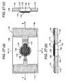
- Fig. 27 shows an actuator constituting the above-described conventional piezoelectric device.
- the actuator 1106 includes a substrate 1178 having a circular opening 1161 substantially in its center, a vibration plate 1176 displaced in one surface (hereinafter, referred to as 'front surface') of the substrate 1178 so as to cover the opening 1161, a piezoelectric layer 1160 disposed on the front surface of the vibration plate 1176, an upper electrode 1164 and a lower electrode 1166 interposing the piezoelectric layer 1160 therebetween, an upper electrode terminal 1168 which is electrically connected to the upper electrode 1164, a lower electrode terminal 1170 which is electrically connected to the lower electrode 1166, and an auxiliary electrode 1172 which is arranged between the upper electrode 1164 and the lower electrode 1168 to electrically connect both of them.
- Each of the piezoelectric layer 1160, the upper electrode 1164, and the lower electrode 1166 has a circular portion serving as a main body.
- the respective circular portions of the piezoelectric layer 1160, the upper electrode 1164, and the lower electrode 1166 constitute a piezoelectric element.
- the vibration plate 1176 is formed on the front surface of substrate 1178 so as to cover the opening 1161.
- the vibration region, which is actually vibrated in the vibration plate 1176, is defined by the opening 1161.
- the cavity 1161 is formed by the part of the vibration plate 1176 facing the opening 1161 and the opening 1161 of the substrate (cavity forming member) 1178.
- the surface (hereinafter, referred to as 'back surface') of the substrate 1178 opposite to the piezoelectric element faces inward to the ink container. Accordingly, the cavity 1162 is constructed so as to be brought into contact the liquid (ink).
- the vibration plate is liquid-tight to the substrate 1178 so that liquid does not leak in the front surface of the substrate 1178 even though liquid enters the cavity 1162.
- the residual vibration (free vibration) of the vibrating portion which is generated after the vibration portion is forcefully vibrated by the vibrating pulse applied to the piezoelectric element, is detected as a back electromotive force by the same piezoelectric element.
- the above-described conventional actuator (piezoelectric device) 1106 is mounted on the container wall of a container body 1181 of the ink cartridge 1180 and is constructed so that the cavity 1162 for receiving ink to be sensed is exposed to the ink reservoir space within the ink cartridge 1180.
- the above-described conventional actuator (piezoelectric device) 1106 is constructed so that the cavity 1162 is exposed to the ink reservoir space within the ink cartridge 1180, as described above. Therefore, if the ink within the ink cartridge 1180 is foamed by a vibration or the like, bubbles easily enter the cavity 1162 of the actuator 1106. If the bubbles enter the cavity 1162 and accumulated therein, the resonant frequency of the residual vibration detected by the actuator 1106 becomes high so that it is erroneously determined that the liquid level passes through the position of the actuator 1106 and the amount of remaining ink becomes small, despite the fact that the amount of ink remaining in the ink cartridge 1180 is adequate.
- the actuator 1106 is constructed so as to expose the cavity 1162 to the ink reservoir space within the ink cartridge 1180, the ink pressure within the ink reservoir space has a direct effect on the vibration plate 1176 and piezoelectric layer 1160 of the actuator 1106. Therefore, in the ink cartridge 1180 or the like, the ink within the ink reservoir space is severely vibrated by the carriage reciprocating on a printing operation, so that the ink pressure generated by the vibration has a direct effect on the actuator 1106, which results in erroneous determination.
- a barrier for preventing a vibration or a wave of ink is formed in the position facing the actuator 1106.
- the space structure around 1106 becomes complicated and the vibration mode of the residual vibration detected by the actuator 1106 also becomes complicated as much. As a result, sensing becomes hard so as to dull detection sensitivity.
- the ink is allowed to freely enter the cavity opposed to the vibration plate, but the ink is not allowed to enter the space in which the piezoelectric element and the like as electrical elements are disposed. Accordingly, the spaces between the adjacent elements should be liquid-tightly sealed at the time of mounting.
- the sealing structure there is known a structure that the sensor unit is bonded directly to the circumferential edge of an opening of the container body or a structure that the sensor unit is bonded directly to the circumferential edge of an opening of a module and then the module is mounted on the container body with an O ring therebetween.
- the sensor unit since the sensor unit is bonded to the circumferential edge of the opening, deviation in size makes it difficult to secure the sealing ability.
- the sensor unit when the sensor unit is bonded directly to the circumferential edge of the opening of the container body or the circumferential edge of the opening of the module, it can be easily affected by a wave motion of the ink or bubbles in the ink, thereby causing erroneous detection.
- a first object of the invention is to provide a mounting structure of a liquid sensor and a liquid container in which detection sensitivity can be enhanced by simplifying a vibration mode and existence of liquid can be reliably determined by reducing influence of vibration from the liquid.
- a second object of the invention is to provide a container having a liquid detecting function in which a sealing work at the time of mounting a sensor unit on a container body can be simply and reliably carried out without being affected by accuracy in sizes of components and which has a structure that is little affected by a wave motion of ink or bubbles in the ink.
- the invention has the following configuration:
- the liquid flowing from the upstream side of the delivery path in the container body is supplied to the sensor cavity through the upstream buffer chamber and the entrance-side flow paths of the unit base and the sensor base and is discharged to the downstream side of the delivery path through the exit-side flow paths of the sensor base and the unit base and the downstream buffer chamber from the sensor cavity, the liquid always flows through the sensor cavity. Accordingly, it is possible to prevent the erroneous detection due to the staying of the liquid or bubbles in the sensor cavity.
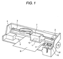
- Fig.,1 shows a schematic configuration of an inkjet printer (liquid jetting apparatus) employing an ink cartridge having a liquid sensor according to the present invention.
- reference numeral 1 denotes a carriage.
- the carriage 1 is guided to a guide member 4 through a timing belt 3 which is actuated by a carriage motor 2 and reciprocates in the axis direction of a platen 5.
- a side of the carriage 1 facing a recording paper 6 is mounted with an inkjet printing head 12 and an ink cartridge 7 for supplying ink to the printing head 12 is detachably fitted thereon.
- a cap member 31 is disposed at a home position (the right side in the figure) which is a non-printing region of the printer.
- the cap member 31 is pressed against a nozzle forming surface of the printing head 12 to form a closed space between the cap member and the nozzle forming surface.
- a pump unit 10 for applying a negative pressure to the closed space formed by the cap member 31 to perform a cleaning work or the like is disposed below the cap member 31.
- a wiping unit 11 having an elastic plate such as rubber or the like is disposed so as to advance and retreat, for example, in the horizontal direction with respect to the moving locus of the printing head 12. Therefore, when the carriage 1 reciprocates toward the cap member 31, the nozzle forming surface of the printing head 12 can be wiped off as needed.
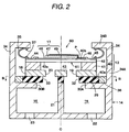
- Fig. 2 is a cross-sectional view illustrating a liquid sensor 60 employing a mounting structure according to a first embodiment of the first aspect of the invention.
- Fig. 3 is a diagram illustrating a sensor unit (sensor) 13 of the liquid sensor 60 and
- Fig. 4 is a diagram illustrating a buffer portion and an elastic seal member 29 constituting the liquid sensor 60.
- the liquid sensor 60 is constituted by the entire elements shown in Fig. 2, which includes the sensor unit 13 corresponding to the sensor according to the invention and the buffer portion 14 corresponding to the mounting target member according to the invention and the liquid sensor 60 is mounted on a container body 72 to be described later, thereby constituting an ink cartridge 70.
- the liquid sensor 60 includes a sensor unit 13 having a cavity 43 and a buffer portion (mounting target member) 14 having a supply-side buffer chamber (upstream space) and a discharge-side buffer chamber (downstream space) 16 which communicate with the cavity 43.
- the sensor unit 13 is mounted on the top surface of the buffer portion 14 with the elastic seal member 29 therebetween and the space between the sensor unit 13 and the buffer portion 14 is sealed with the elastic seal member 29.
- the sensor unit 13 is pressed and fixed onto the top surface of the buffer portion 14 by means of a sensor fixing member 34 and a bias member 35 having a hook shape formed on the top surface of the buffer portion 14.
- the sensor unit 13 in which a vibration plate 42 is stacked on a cavity plate 41 includes a vibration cavity forming base portion 40 having a first surface 40a and a second surface 40b which are opposed to each other, a piezoelectric element 17 stacked on the side of the second surface 40b of the vibration cavity forming base portion 40, and a flow path forming plate (flow path forming base portion) 18 stacked on the side of the first surface 40a of the vibration cavity forming base portion 40.
- the cavity 43 for receiving a medium (ink) to be sensed is defined by a cylindrical space so as to be opened to the first surface 40a and a bottom portion 43a of the cavity 43 is formed so as to be vibrated by the vibration plate 42.
- an outline of an actually vibrated portion in the entire vibration plate 42 is defined by the cavity 43.
- a lower electrode terminal 44 and an upper electrode terminal 45 are formed on both ends of the vibration cavity forming base portion 40 on the side of the second surface 40b.
- a lower electrode (a first electrode) 46 is formed, which has a body portion 46a having a substantially circular shape and an extension portion 46b extending toward the lower electrode terminal 44 from the body portion 46a to be connected to the lower electrode terminal 44.
- the center of the substantially circular body portion 46a of the lower electrode 46 is brought into line with the center axis C of the cavity 43.
- the substantially circular body portion 46a of the lower electrode 46 is formed so as to have a larger diameter than that of the circular cavity 43 and to cover the substantially entire portion of the region corresponding to the cavity 43. Further, the substantially circular body portion 46a of the lower electrode 46 includes a notched portion 46c which is formed further inward from a position corresponding to a circumferential edge 43b of the cavity 43.
- a piezoelectric layer 47 is stacked on the lower electrode 46 and the piezoelectric layer 47 includes a circular body portion 47a with a smaller diameter than that of the cavity 43 and a projected portion 47b projected from the body portion 47a in the range of the region corresponding to the cavity 43.
- the entire portion of the piezoelectric layer 47 belongs to the range of the region corresponding to the cavity 43.
- the piezoelectric layer 47 does not have nay portion extending across the position corresponding to the circumferential edge 43b of the cavity 43.
- the center of the body portion 47a of the piezoelectric layer 47 is brought into line with the center axis C of the cavity 43.
- the substantially entire portion of the body portion 47a of the piezoelectric layer 47 is stacked on the lower electrode 46, except for the portion corresponding to the notched portion 46c of the lower electrode 46.
- An auxiliary electrode 48 is formed on the second surface 40b of the vibration cavity forming base portion 40.
- the auxiliary electrode 48 extends over the position corresponding to the circumferential edge 43b of the cavity 43 to the inside of the region corresponding to the cavity 43 from the outside of the region corresponding to the cavity 43.
- a portion of the auxiliary electrode 48 is positioned inside the notched portion 46c of the lower electrode (the first electrode) 46 to support the projected portion 47b of the piezoelectric layer 47 and the peripheral portion thereof from the side of the second surface 40b of the vibration cavity forming base portion 40.
- the auxiliary electrode 48 is preferably made of the same material as the lower electrode 46 and has the same thickness as the lower electrode 46.
- the circular body portion 49a of the upper electrode (second electrode) 49 is stacked on the piezoelectric layer 47 and the upper electrode 49 has a diameter smaller than that of the body portion 47a.
- the upper electrode 49 has an extension portion 49b which is projected from the body portion 49a and is connected to the auxiliary electrode 48. As can be seen from Fig. 2, a position P where the extension portion 49b of the upper electrode 49 first comes in contact with the auxiliary electrode 48 is positioned in the region corresponding to the cavity 43.
- the respective body portions of the lower electrode 46, the piezoelectric layer 47, and the upper electrode 49 constitute a piezoelectric element 17.
- the upper electrode 49 is electrically connected to an upper electrode terminal 45 through the auxiliary electrode 48.
- the level difference resulting from the total thickness of the piezoelectric layer 47 and the lower electrode 46 can be absorbed by both of the upper electrode 49 and the auxiliary electrode 48. Accordingly, it is possible to prevent the mechanical strength from being reduced due to a large level difference in the upper electrode 49.
- the body portion 49a of the upper electrode 49 has a circular shape and the center thereof is brought into line with the center axis C of the cavity 43.
- the body portion 49a of the upper electrode 49 has a diameter smaller than those of the body portion 47a of the piezoelectric layer 47 and the cavity 43.
- the body portion 47a of the piezoelectric layer 47 is interposed between the body portion 49a of the upper electrode 49 and the body portion 46a of the lower electrode 46. Accordingly, the piezoelectric layer 47 can be effectively deformed and actuated.
- the body portion 49a of the upper electrode 49 has the smaller diameter among the body portion 46a of the lower electrode 46 and the body portion 49a of the upper electrode 49 electrically connected to the piezoelectric layer 47. Therefore, the body portion 49a of the upper electrode 49 determines the range of the portion where the piezoelectric effect is generated from the piezoelectric layer 47.
- the respective centers of the body portion 47a of the piezoelectric layer 47, the body portion 49a of the upper electrode 49, and the body portion 46a of the lower electrode 46 are brought into line with the center axis C of the cavity 43.
- the center axis C of the cylindrical cavity 43 determining the range of the portions where the vibration plate 42 can vibrate is positioned in the center of the whole liquid sensor 60.
- the portion of the vibration plate 42 which is defined by the cavity 43 and can vibrate, the portion of the body portion 46a of the lower electrode 46 corresponding to the cavity 43, and the portions of the body portion 47a and the extension portion 47b of the piezoelectric layer 47 and the body portion 49a and the extension portion 49b of the upper electrode 49 corresponding to the cavity 43 constitute the vibration portion 61 of the liquid sensor 60.
- the center of the vibration portion 61 of the liquid sensor 60 is brought into line with the center of the liquid sensor 60.
- the body portion 47a of the piezoelectric layer 47, the body portion 49a of the upper electrode 49, the body portion 46a of the lower electrode 46, and the portion which can vibrate among the vibration plate 42 (the portion corresponding to the bottom surface 43a of the cavity 43) have a circular shape and the whole piezoelectric layer 47, that is, the body portion 47a and the extension portion 47b of the piezoelectric layer 47, is disposed inside the region corresponding to the cavity 43. Accordingly, the vibration portion 61 of the liquid sensor 60 is substantially symmetric about the center of the liquid sensor 60.
- the liquid sensor 60 includes a flow path forming plate (flow path forming base portion) 18 stacked on and bonded to the first surface 40a of the vibration cavity forming base portion 40.
- An ink supply path (liquid supply path) 19 for supplying ink as a detection target to the cavity 43 and an ink discharge path (liquid discharge path) 20 for discharging the ink as the detection target from the cavity 43 are formed in the flow path forming plate 18.
- the ink supply path 19 and the ink discharge path 20 have the same size and shape, that is, a cylindrical shape.
- the ink supply path 19 and the ink discharge path 20 formed in the flow path forming plate 18 are formed in the region corresponding to the circular cavity 43 and the ink supply path 19 and the ink discharge path 20 are disposed to be symmetric about the center axis C of the cavity 43. Accordingly, the cavity 43, the space including the ink supply path 19, and the ink discharge path 20 is symmetric about the center axis C of the cavity 43 in the region between the ink supply path 19 and the ink discharge path 20.
- the ink supply path 19 and the ink discharge path 20 have a flow path area smaller than that of the cavity 43. That is, in the present embodiment, one ink supply path 19 and one ink discharge path 20 are formed in one cavity 43 and the flow path area of any one flow path (the ink supply path 19 or the ink discharge path 20) is set smaller than half an area of the cavity 43.
- the ink supply path 19 and the ink discharge path 20 have a length so that fluidal mass of liquid exists therein.
- the liquid sensor 60 includes a buffer portion having a supply-side buffer chamber 15 which communicates with the ink supply path 19 and in which the ink supplied to the ink supply path 19 exists and a discharge-side buffer chamber 16 which communicates with the ink discharge path 20 and in which the ink discharged from the ink discharge path 20 exists.
- the buffer portion 14 has a rectangular shape slightly greater than the liquid sensor 60 as seen in the plan view as a whole.
- the inside of the buffer portion 14 is divided into two spaces having the same size and shape by a partition wall 21 disposed at the center thereof.
- One is the supply-side buffer chamber 15 and the other is discharge-side buffer chamber 16.
- An inflow opening 22 for allowing the ink to flow in the supply-side buffer chamber 15 and an outflow opening 23 for allowing the ink to flow out of the discharge-side buffer chamber 16 are formed in the surface of the buffer portion 14 opposite to the surface on which the sensor unit 13 is mounted.
- An upper opening 30A for supplying the ink flowing in the supply-side buffer chamber 15 to the cavity 43 through the ink supply path 19 and an upper opening 30B for discharging the ink in the cavity 43 to the supply-side buffer chamber 15 through the ink discharge path 20 are formed in the surface of the buffer portion 14 on which the sensor unit 13 is mounted.
- the elastic seal member 29 is interposed between the sensor unit 13 and the buffer portion 14.
- the elastic seal member 29 includes a supply-side opening 32 allowing the ink supply path 19 and the supply-side buffer chamber 15 to communicate with each other and a discharge-side opening 33 allowing the ink discharge path 20 and the discharge-side buffer chamber 16 to communicate with each other and seals the space between the ink supply path 19 and the supply-side buffer chamber 15 and the space between the ink discharge path 20 and the discharge-side buffer chamber 16.
- the elastic seal member 29 may be made of an elastic material such as rubber and elastomer and may be preferably made of a vibrationproof elastic material that polymers having a three-dimensional network structure are mixed with oil and appropriate hardness, loss characteristic, and spring constant are set.
- the elastic seal member 29 has a rectangular plate shape slightly larger than the sensor unit 13 as a whole and slightly smaller than the buffer portion 14.
- a synthetic-resin holding member 36 which has a quadrangular section and a quadrangular frame shape so as to hold the elastic seal member 29, is fitted to the outer circumference of the elastic seal member 29.
- the holding member 36 has a height substantially equal to the thickness of the elastic seal member 29 and positions the elastic seal member 29 at a predetermined position on the top surface of the buffer portion 14 by bringing the left and right ends into contact with the left and right sensor fixing members 34.
- the sensor fixing members 34 having a hook shape, which extend upwardly and of which the ends are bent inwardly, are formed on the left and right ends of the top surface of the buffer portion 14.
- the sensor fixing member 34 is provided by rising a plate-shaped vertical piece 34A extending vertically in Fig. 2 on the left and right sides of the top surface of the buffer portion 14.
- a plate-shaped horizontal piece 34B is bent inwardly in a hook shape from the end of the vertical piece 34A.
- Positioning projections 37 for positioning the bias member 35 are formed on the bottom surfaces of the horizontal pieces 34B of the sensor fixing members 34 and the top surfaces of the lower electrode terminal 44 and the upper electrode terminal 45.
- the bias members 35 are formed of a U-shaped leaf spring which falls horizontally and insertion holes (not shown) into which the projections are inserted are formed in the vicinity of the U-shaped free ends fallen horizontally.
- the elastic seal member 29 into which the holding members 36 are externally inserted is mounted on the top surface of the buffer portion 14, the sensor unit 13 is mounted thereon, the U-shaped bias members 35 fallen horizontally are inserted between the horizontal pieces 34B of the sensor fixing members 34 and the top surface of the sensor unit 13 while compressing the bias members, the insertion holes of the bias members 35 are fitted to the horizontal pieces 34B of the sensor fixing members 34 and the projections on the top surface of the sensor unit 13. Accordingly, the sensor unit 13 can be positioned at an appropriate position on the elastic seal member 29, the sensor unit 13 is biased toward the buffer portion 14 with the biasing force of the bias members 35, and then the sensor unit is pressed and fixed to the top surface of the buffer portion 14. By the use of the pressurizing force, the sealing property between the ink supply path 19 and the supply-side buffer chamber 15 and between the ink discharge path 20 and the discharge-side buffer chamber 16 is maintained by the elastic seal member 29.
- the supply-side opening 32 and the discharge-side opening 33 of the elastic seal member 29 are disposed on the upper openings 30A and 30B of the buffer portion 14, respectively.
- the ink supply path 19 and the ink discharge path 20 of the sensor unit 13 are disposed on the supply-side opening 32 and discharge-side opening 33 of the elastic seal member 29, respectively.
- the ink in the cartridge which is the detection target flows in the supply-side buffer chamber 15 from the inflow opening 22 and then is supplied to the cavity 43 through the upper opening 30A, the supply-side opening 32, and the ink supply path 19.
- the ink supplied to the cavity 43 is discharged to the discharge-side buffer chamber 16 through the ink discharge path 20, the discharge-side opening 33, and the upper opening 30B and then is discharged from the discharge-side buffer chamber 16 through the outflow opening 23.
- the ink supply path 19 and the ink discharge path 20 have the same size of a cylindrical shape as described above.
- the supply-side opening 32 and the discharge-side opening 33 are formed in a substantially circular opened space and have the same shape and size in the present embodiment.
- the opening of the supply-side opening 32 of the elastic seal member 29 is set larger than the opening of the ink supply path 19 of the sensor unit 13.
- the opening of the discharge-side opening 33 of the elastic seal member 29 is set larger than the opening of the ink discharge path 20 of the sensor unit 13.
- a ratio of the opening diameters D1 and D3 of the ink supply path 19 and the ink discharge path 20 of the sensor unit and the opening diameters D2 and D4 of the supply-side opening 32 and the discharge-side opening 33 of the elastic seal member 29 can be set appropriately.
- the opening diameter D2 of the supply-side opening 32 of the elastic seal member 29 is set two or more times greater than the opening diameter D1 of the ink supply path 19 of the sensor unit 13 and the opening diameter D4 of the discharge-side opening 33 of the elastic seal member 29 is set two or more times greater than the opening diameter D3 of the ink discharge path 20 of the sensor unit 13.
- the supply-side opening 32 of the elastic seal member 29 and the liquid supply path 19 of the sensor unit 13 are disposed concentrically and the discharge-side opening 33 of the elastic seal member 29 and the liquid discharge path 20 of the sensor unit 13 are disposed concentrically.
- the space formed by the ink supply path 19, the supply-side opening 32, the ink discharge path 20, and the discharge-side opening 33 is symmetrical about the center axis C of the cavity 43.
- the supply-side buffer chamber 15, the upper opening 30A, the discharge-side buffer chamber 16, and the upper opening 30B of the liquid sensor 60 are symmetrical about the center axis C of the cavity 43.
- the space formed by the cavity 43, the ink supply path 19, the ink discharge path 20, the supply-side opening 32, the discharge-side opening 33, the upper openings 30A and 30B, the supply-side buffer chamber 15, and the discharge-side buffer chamber 16 is symmetrical about the center axis C of the cavity 43.
- the volumes of the supply-side buffer chamber 15 and the discharge-side buffer chamber 16 of the liquid sensor 60 are set to have at least ten times greater than the volume of the cavity 43.
- the cavity plate 41, the vibration plate 42, and the flow path forming plate 18 are made of the same material and integrally formed by being sintering with one another. As such, a plurality of substrates is sintered to form a body, handling of the liquid sensor 60 becomes easy. Further, since the respective members are made of the same material, a crack can be prevented from occurring due to the difference among their linear expansion coefficients.
- the piezoelectric layer 47 As a material of the piezoelectric layer 47, it is preferable that lead zirconate titanate (PZT), lead lanthanum zirconate titanate (PLZT), or a leadless piezoelectric film is used.
- PZT lead zirconate titanate
- PLAT lead lanthanum zirconate titanate
- a leadless piezoelectric film As a material of the cavity plate 41, zirconia or alumina is preferably used. Further, for the vibration plate 42, the same material as that of the cavity plate 41 is preferably used.
- the upper electrode 49, lower electrode 46, upper electrode terminal 45 and lower electrode terminal 44 can be made of metallic materials such as gold, silver, copper, platina, aluminum, nickel, and the like, which have a conductivity.
- Fig. 5 is a diagram illustrating the ink cartridge 70 of the present invention including the liquid sensor and Fig. 6 is a diagram illustrating an example of the liquid sensor mounted on the ink cartridge 70.
- Fig. 5 shows the ink cartridge (liquid container) 70 with the liquid sensor 60 mounted thereon.
- the ink cartridge 70 includes a container body 72 having an ink outlet port (liquid outlet port) 71 for delivering the ink reserved inside to the outside.
- the liquid sensor 60 as a whole is mounted on the container body 72.
- the buffer portion 14 is fixed in a liquid-tight manner by an adhesive 28 or the like.
- the sensor portion 13 of the liquid sensor 60 is disposed outside the container body 72 so that an inflow opening 22 and an outflow opening 23 of the buffer portion 14 are opened inside the container body 72.
- the inside of the container body 72 (refer back to Fig. 5) is partitioned into a main reservoir chamber(liquid reservoir chamber) 75, which constitutes the major part of the entire inner space of the container body 72 to reserve ink, and a sub reservoir chamber(liquid delivery space) 76 having a smaller volume than the main reservoir chamber 75.
- the main reservoir chamber 75 is separated from the sub reservoir chamber 76.
- the sub reservoir chamber 76 is positioned in the side which is closer to the ink outlet port 71 than to the main reservoir chamber 75 in the flow direction of ink when the ink is consumed.
- the inflow opening 22 of the liquid sensor 60 is opened so as to communicate with the main reservoir chamber 75, the outflow opening 23 is disposed so as to be opened into the sub reservoir chamber 76 which is the liquid delivery space.
- the supply side buffer chamber 15 constitutes the major part of the inner space of the container body 72 to communicate with the main reservoir chamber 75 for reserving liquid.
- the discharge side buffer chamber 16 is disposed so as to communicate with the liquid delivery space in the inner space of the container body 72.
- the liquid delivery space communicates with the ink outlet port 71 for delivering the ink reserved inside to the outside.
- a closed auxiliary flow path 77 is formed inside the main reservoir chamber 75, and, an auxiliary flow path entrance 77a is formed at a lower end of the auxiliary flow path 77.
- the auxiliary flow path entrance 77a is positioned at the lower end inside the main reservoir chamber 75. Further, the inflow opening 22 of the liquid sensor 60 communicates with the upper end of the auxiliary flow path 77 to constitute an exit of the auxiliary flow path 77.
- the inflow opening 22 of the liquid sensor 60 communicates with the main reservoir chamber 75 through the auxiliary flow path 77, and the outflow opening 23 communicates with the ink outlet port 71 through the sub reservoir chamber 76. Accordingly, the ink reserved in the main reservoir chamber 75 flows in the supply side buffer chamber 15 from the inflow opening 22 via the auxiliary flow path 77 to be supplied to the cavity 43 through the upper opening 30A, the supply side opening 32 and the ink supply path 19.
- the ink supplied to the cavity 43 is discharged into the discharge side buffer chamber 16 through the ink discharge flow path 20, the discharge side opening 33 and upper opening 30B, and the ink is discharged from the ink outlet port 71 via the outflow opening 23 and the sub reservoir chamber 76 from the discharge side buffer chamber 16, to be finally supplied to the printing head 12.
- the entire ink delivered to the ink outlet port 71 through the sub reservoir chamber 76 passes through the ink supply path 19 and the ink discharge path 20 of the liquid sensor 60 in advance.
- the liquid sensor 60 and the ink cartridge 70 include the vibration cavity forming base portion 40 which is formed with ink supply path 19 for supplying ink to the cavity 43 and the ink discharge path 20 for discharging ink from the cavity 43, so that the ink supply into the cavity 43 is performed through the ink supply path 19 and the ink discharge from the cavity 43 is performed through the ink discharge path 20. Therefore, when the liquid sensor 60 is mounted on the ink cartridge 70 or the like, the cavity 43 of the liquid sensor 60 is no directly exposed to the ink reservoir space and ink can be supplied to the cavity 43 through the ink supply path 19.
- the cavity 43 does not need to be exposed to the ink storage space, meniscus can be prevented from being formed inside the cavity 43 when ink passes through the liquid level. Accordingly, erroneous detection of the liquid sensor 60 can be prevented, which is caused by the ink remaining inside the cavity 43. Furthermore, the cavity 43 is not exposed toward the ink reservoir space, but is enclosed from the ink reservoir space by the flow path forming plate 18. Therefore, due to a change of ink level, the existence of ink and the like, a difference in the residual vibration remaining in the vibration portion 61 becomes large when the vibration portion 61 is forced to be vibrated, so that detection sensitivity becomes high to enhance detection precision and to prevent erroneous detection.
- the elastic seal member 29 is disposed between the sensor unit 13 and the buffer portion 14, has a supply-side opening 32 allowing the liquid supply path 19 and the supply-side buffer chamber 15 to communicate with each other and a discharge-side opening 33 allowing the liquid discharge path 20 and the discharge-side buffer chamber 16 to communicate with each other, and seals a gap between the liquid supply path 19 and the supply-side buffer chamber 15 and a gap between the liquid discharge path 20 and the discharge-side buffer chamber 16, it is possible to secure the detection accuracy and to simplify the manufacturing processes.
- the adhesive can be easily pressed out into the flow path formed by the liquid supply path 19 and the supply-side buffer chamber 15 or the flow path formed by the liquid discharge path 20 and the discharge-side buffer chamber 16. Then, since the bubbles are attached to the pressed-out adhesive and are not removed well, the bubbles have an influence on the residual vibration of the vibration portion 61 of the cavity 43, thereby badly affecting the detection accuracy. Therefore, it should be managed not to press out the adhesive into the flow paths, thereby complicating the bonding process.
- the elastic seal member 29 seals the space between the liquid supply path 19 and the supply-side buffer chamber 15 and the space between the liquid discharge path 20 and the discharge-side buffer chamber 16, the adhesive is not pressed out into the flow paths at all, thereby solving the decrease in detection accuracy due to the attachment of bubbles or the complication of processes for managing not to press out the adhesive.
- the opening of the supply-side opening 32 of the elastic seal member 29 is larger than the opening of the liquid supply path 19 of the sensor unit 13 and the opening of the discharge-side opening 33 of the elastic seal member 29 is larger than the opening of the liquid discharge path 20 of the sensor unit 13.
- the opening diameter D2 of the supply-side opening 32 of the elastic seal member 29 is set two or more times greater than the opening diameter D1 of the ink supply path 19 of the sensor unit 13 and the opening diameter D4 of the discharge-side opening 33 of the elastic seal member 29 is set two or more times greater than the opening diameter D3 of the ink discharge path 20 of the sensor unit 13.
- the supply-side opening 32 of the elastic seal member 29 and the liquid supply path 19 of the sensor unit 13 are disposed concentrically and the discharge-side opening 33 of the elastic seal member 29 and the liquid discharge path 20 of the sensor unit 13 are disposed concentrically. Accordingly, even when the vibration of the bottom surface of the cavity 43 is slightly delivered to the elastic seal member 29 through the ink, the vibration mode generated in the elastic seal member 29 can be further simplified by disposing the supply-side opening 32 and liquid supply path 19 and the discharge-side opening 33 and liquid discharge path 20, respectively, in a concentric manner. Accordingly, it is possible to suppress the decrease in detection accuracy due to the vibration generated in the elastic seal member 29 as much as possible.
- the openings of the liquid supply path 19 and the liquid discharge path 20 are set to the same size and shape and the openings of the supply-side opening 32 and the discharge-side opening 33 are set to the same size and shape.
- the supply-side opening 32 and liquid supply path 19 and the discharge-side opening 33 and liquid discharge path 20 are symmetric about the center axis C of the cavity 43.
- the shape of the space including the liquid supply path 19, the supply-side opening 32, the liquid discharge path 20, the discharge-side opening 33, and the cavity 43 through which the vibration of the bottom surface of the cavity 43 is spread is simplified and thus the vibration mode of the residual vibration remaining on the bottom surface of the cavity 43 is also simplified. Accordingly, the simulation for the residual vibration when the bottom surface of the cavity is compulsorily vibrated can be easily performed to reduce the difference between the actual phenomenon and the designed effect. As a result, the adjustment work can be reduced or the detection accuracy can be improved.
- the space constituting the cavity 43 is substantially circular, the space shape of the cavity 43 through which the vibration of the bottom surface of the cavity 43 is more simplified and thus the vibration mode of the residual vibration remaining on the bottom surface of the cavity 43 is also simplified. Accordingly, the simulation for the residual vibration when the bottom surface of the cavity 43 is compulsorily vibrated can be easily performed to reduce the difference between the actual effect and the designed effect. As a result, the adjustment work can be reduced or the detection accuracy can be improved.
- the ink supply path 19 and the ink discharge path 20 are set to have a flow path area smaller than that of the cavity 43 and to have such a length that fluidal mass exists therein, an appropriate flow-path resistance is generated in the ink supply path 19 and the ink discharge path 20. Accordingly, it is possible to prevent the variation in pressure in the cavity 43 due to the vibration of the bottom surface of the cavity 43 from being spread into both buffer chambers 15 and 16 and to generate appropriate residual vibration, thereby enhancing and securing the detection accuracy.
- the sensor unit 13 since there is further provided a bias member 35 for fixing the sensor unit 13 to the buffer portion 14 by biasing the sensor unit 13 toward the buffer portion 14, the sensor unit 13 can be reliably mounted on the buffer portion 14 by the use of the biasing force of the bias member 35 and the elastic seal member 29 is compressed by the biasing member, thereby little causing the deformation. Accordingly, even when the vibration of the bottom surface of the cavity 43 is slightly delivered to the elastic seal member 29 through the liquid, the elastic seal member 29 little vibrates.
- the holding member 36 mounted on the outer circumference of the elastic seal member 29 to hold the elastic seal member 29 from the periphery thereof, the deformation of the elastic seal member 29 toward the outer circumference is regulated by the holding member 36 and the deformation of the elastic seal member 29 is further suppressed when the elastic seal member 29 is compressed by the biasing force of the bias member 35. Accordingly, even when the vibration of the bottom surface of the cavity 43 is slightly delivered to the elastic seal member 29 through the liquid, the vibration of the elastic seal member 29 is further suppressed. Therefore, it is possible to effectively prevent the decrease in detection accuracy due to the vibration of the elastic seal member 29.
- the mounting target member is a buffer portion 14 which has as an upstream space a supply-side buffer chamber 15 communicating with the liquid supply path 19 and as a downstream space a discharge-side buffer chamber 16 communicating with the liquid discharge path 20. Therefore, the ink supply path 19 and the ink discharge path 20 through which the liquid enters and leaves the cavity 43 are opened to the supply-side buffer chamber 15 and the discharge-side buffer chamber 16, respectively, but not opened directly to the ink reserving space of the container body 72. Accordingly, even when the bubbles are generated due to the vibration of the ink in the ink reserving space, the bubbles are once trapped by the supply-side buffer chamber 15 or the discharge-side buffer chamber 16 and little enter the cavity 43.
- the ink supply path 19 and the ink discharge path 20 through which the liquid enters and leaves the cavity 43 are opened to the supply-side buffer chamber 15 and the discharge-side buffer chamber 16, respectively, but not opened directly to the ink reserving space of the container body 72, the pressure of the ink in the ink reserving space of the ink cartridge 70 does not act directly on the cavity 43. Therefore, it is possible to prevent the erroneous detection of the liquid sensor 60 due to the influence of pressure from the vibration of ink.
- the shape of the members forming both buffer chambers 15 and 16 is simplified by allowing the supply-side buffer chamber 15 and the discharge-side buffer chamber 16 to be symmetrical, thereby facilitating the manufacturing work and accomplishing decrease in size of the members.
- the supply-side buffer chamber 15 and the discharge-side buffer chamber 16 of the liquid sensor 60 have a volume ten or more times greater than the volume of the cavity 43, the variation in pressure of the ink generated in the ink reserving space of the ink cartridge 70 little affects the sensor characteristic of the liquid sensor 60. Accordingly, it is possible to prevent erroneous detection of the liquid sensor 60 due to the influence of pressure such as the vibration of the ink.
- the pressure in both buffer chambers 15 and 16 is not increased due to the vibration of the bottom surface of the cavity 43, extra vibration is not generated and thus the vibration mode of the residual vibration remaining on the bottom surface of the cavity 43 is simplified, thereby enhancing the detection accuracy.
- the buffer portion 14 is mounted on the container body 72 having an ink outlet port 71 for sending out the ink reserved therein
- the supply-side buffer chamber 15 constitutes a main part of the inner space of the container body 72 and communicates with a main reservoir chamber 75 reserving the ink
- the discharge-side buffer chamber 16 communicates with a sub reservoir chamber 76 which is an ink delivery space communicating with the ink outlet port 71 for sending out the ink reserved in the inner space of the container body 72. Accordingly, the ink reserved in the main reservoir chamber 75 of the container body 72 flows in the entrance of the supply-side buffer chamber 15 of the liquid sensor 60, is discharged from the exit of the discharge-side buffer chamber 16, and is sent to the ink outlet port 71 of the container body 72.
- the whole amount of ink sent to the ink outlet port 71 of the container body 72 previously passes through the supply-side buffer chamber 15, the cavity 43, and the discharge-side buffer chamber 16 of the liquid sensor 60. As a result, it is possible to reliably detect consumption of the liquid.
- the ink discharge path 20 is formed to correspond to the corresponding region of the cavity 43, it is possible to satisfactorily discharge the bubbles entering the cavity 43.
- the inside of the container body 72 is partitioned into a main reservoir chamber 75 and a sub reservoir chamber 76 isolated from each other, the main reservoir chamber 75 and the sub reservoir chamber 76 communicate with each other through the inflow opening 22 and the outflow opening 23 of the liquid sensor 60, and the cavity 43 of the liquid sensor 60 is disposed on the top surface of the sub reservoir chamber 76.
- a closed auxiliary flow path 77 is formed inside the main reservoir chamber 75, the auxiliary flow path inlet 77a of the auxiliary flow path 77 is disposed in the lower end of the main reservoir chamber 75, and the inflow opening 22 of the liquid sensor 60 communicates with the upper end of the auxiliary flow path 77. For this reason, the bubbles produced in the main reservoir chamber 75 hardly enter the auxiliary flow path 77 and can be prevented from entering the cavity 43 of the liquid sensor 60.
- the inside of the sub reservoir chamber 76 is filled with ink until all the ink in the main reservoir chamber 75 is consumed. Therefore, even when vibration is applied to the ink cartridge 70, the liquid level in the sub reservoir chamber 76 does not shake as long as ink remains in the main reservoir chamber 75. Accordingly, erroneous detection of the liquid sensor 60 caused by the shake of the liquid level can be prevent from occurring.
- liquid sensor 60 the range where the vibration portion 61 comes in contact with ink is limited to the range corresponding to the cavity 43. Therefore, pinpoint detection of ink can be performed, so that the ink level can be sensed with high precision.
- the vibration portion 61 of the liquid sensor 60 is formed symmetrically with respect to the center of the liquid sensor 60, the rigidity of the vibration portion 61 is nearly isotropic, as seen from the center.
- the entire piezoelectric layer 47 which is inherently brittle, is disposed inside the region corresponding to the cavity 43 and does not exist in the position corresponding to the peripheral edge 43b of the cavity 43. For this reason, the occurrence of a crack of piezoelectric film is prevented in the position corresponding to the peripheral edge of the cavity.
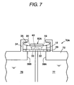
- Figs. 7 show an ink cartridge mounted with a liquid sensor according to a second embodiment of the first aspect of the present invention.
- the liquid sensor 60A includes only the sensor unit 13, not the buffer portion 14.
- an upstream opening 38A allowing the ink supply path 19 of the sensor unit 13 and the auxiliary flow path 77 of the container body 72 to communicate with each other and a downstream opening 38B allowing the ink discharge path 20 of the sensor unit 13 and the sub reservoir chamber 76 of the container body 72 to communicate with each other are formed in the wall of the container body 72.
- a sensor fixing member 34 for fixing the sensor unit is formed on the outer side surface of the container body 72 and the elastic seal member 29 and the sensor unit 13 are positioned and fixed to the outer side surface of the container body 72, similarly to the first embodiment.
- the auxiliary flow path 77 serves as the upstream space, that is, buffer chamber
- the sub reservoir chamber 76 serves as the downstream space, that is, buffer chamber.
- Other structures are similar to the first embodiment and like elements are denoted by like reference numerals.
- the present invention has advantages similar to the first embodiment.
- Fig. 8 shows a liquid sensor 60B according to a third embodiment of the first aspect of the invention.
- Fig. 9 is a diagram illustrating a sensor unit 13 of the liquid sensor 60B and
- Fig. 10 is a diagram illustrating a buffer portion 14 of the liquid sensor 60B.
- the liquid sensor 60B is different from the first embodiment in that a flow path projection 58 in which the upstream flow path 55 and the downstream flow path 56 are opened is protruded from the surface of the buffer portion 14 opposed to the sensor unit 13.
- Other structures are similar to the first embodiment and like elements are denoted by like reference numerals.
- the flow path projection 58 has a trapezoidal shape like a track as seen in the plan view and the upstream flow path 55 and downstream flow path 56 are opened on the mounting surface.
- a ring-shaped projection 57 surrounding both openings of the upstream flow path 55 and the downstream flow path 56 is formed on the surface of the flow path projection 58 opposed to the sensor unit 13.
- the ring-shaped projection 57 has the same track shape as the planar shape of the flow path projection 58 and the upstream flow path 55 and the downstream flow path 56 are opened inside the ring-shaped projection 57.
- the ring-shaped projection 57 Because of existence of the ring-shaped projection 57, when the surface in which the upstream flow path 55 and the downstream flow path 56 of the flow path projection 58 is pressed against the sensor unit 13, the ring-shaped projection 57 is slightly deformed to come in close contact with the flow path forming plate 18 of the sensor unit 13. Consequently, the fine gap resulting from the flatness of the bonding portion between the bottom surface of the flow path forming plate 18 or the top surface of the flow path projection 58 is reduced very small.
- the elastic seal member 29B is interposed between the sensor unit 13 and the buffer portion 14 so as to seal the space between the sensor unit 13 and the buffer portion 14 at the outer circumference thereof.
- the elastic seal member 29B has a rectangular plate shape slightly larger than the sensor unit 13 as a whole and slightly smaller than the buffer portion 14. A track-shaped opening into which the flow path projection 58 is inserted is formed at the center of the elastic seal member 29B. The thickness of the elastic seal member 29B is larger than the height of the flow path projection 58. Accordingly, by pressing the sensor unit 13 against the buffer portion 14, the elastic seal member is compressed to seal the space between the sensor unit 13 and the buffer portion 14.
- the elastic seal member 29B may be made of an elastic material such as rubber and elastomer and may be preferably made of a vibrationproof elastic material (Micro Network Controlled Structure) that polymers having a three-dimensional network structure are mixed with oil and appropriate hardness, loss characteristic, and spring constant are set.
- a vibrationproof elastic material Micro Network Controlled Structure
- the sensor fixing members 34 having a hook shape, in which the end extending upwardly is bent inwardly, are formed on the left and right sides of the top surface of the buffer portion 14.
- the sensor fixing member 34 is provided by rising a plate-shaped vertical piece 34A extending vertically in Fig. 8 on the left and right sides of the top surface of the buffer portion 14.
- a plate-shaped horizontal piece 34B is bent inwardly in a hook shape from the end of the vertical piece 34A.
- Positioning projections 37 for positioning the bias member 35 are formed on the bottom surfaces of the horizontal pieces 34B of the sensor fixing members 34 and the top surfaces of the lower electrode terminal 44 and the upper electrode terminal 45 of the sensor unit 13.
- the bias member 35 is formed of a U-shaped leaf spring which falls horizontally and insertion holes (not shown) into which the projections are inserted are formed in the vicinity of the U-shaped free ends fallen horizontally.
- the elastic seal member 29B is mounted on the top surface of the buffer portion 14, the sensor unit 13 is mounted thereon, the U-shaped bias members 35 fallen horizontally are inserted between the horizontal pieces 34B of the sensor fixing members 34 and the top surface of the sensor unit 13 while compressing the bias members, the insertion holes of the bias members 35 are fitted to the horizontal pieces 34B of the sensor fixing members 34 and the projections on the top surface of the sensor unit 13. Accordingly, the sensor unit 13 can be positioned at an appropriate position on the elastic seal member 29B, the sensor unit 13 is biased toward the buffer portion 14 with the biasing force of the bias members 35, and then the sensor unit is pressed and fixed to the top surface of the buffer portion 14. By the use of the pressurizing force, the sealing property between the ink supply path 19 and the supply-side buffer chamber 15 and between the ink discharge path 20 and the discharge-side buffer chamber 16 is maintained by the elastic seal member 29B.
- the upstream flow path 55 and the downstream flow path 56 are formed in a substantially cylinder-shaped flow path space and have the same size and shape.
- the openings of the upstream flow path 55 and the downstream flow path 56 are matched with the openings of the ink supply path 19 and the ink discharge path 20.
- a liquid supply path is formed by the ink supply path 19 and the upstream flow path 55 and a liquid discharge path is formed by the ink discharge path 20 and the downstream flow path 56.
- the ink in the ink cartridge as the detection target flows in the supply-side buffer chamber 15 from the inflow opening 22 and is supplied to the cavity 43 through the upstream flow path 55 and the ink supply path 19.
- the ink supplied to the cavity 43 is discharged to the discharge-side buffer chamber 16 through the ink discharge path 20 and the downstream flow path 56 and is discharged from the discharge-side buffer chamber 16 through the outflow opening 23.
- any one of the ink supply path 19 and the ink discharge path 20 formed in the above-described flow path forming plate is formed inside the region corresponding to the circular cavity 43, and the upstream flow path 55 and the downstream flow path 56 are disposed symmetrically with respect to the center axis C of cavity 43. Accordingly, the space, which is defined by the cavity 43, the ink supply path 19, the upstream flow path 55, the downstream flow path 56 and the ink discharge path 20, is formed symmetrically with respect to the center axis C of the cavity 43 which exists in the region interposed between the ink supply path 19 and the ink discharge path 20
- the upstream flow path 55 and the downstream flow path 56 are narrowed with respect to the cavity 43, respectively and arranged to have a fluid weight of the liquid inside. That is, in this embodiment, one upstream flow path and one downstream flow path are formed for a cavity 43 and the area of one flow path (upstream flow path 55 or downstream flow path 56) is set to be less than the half of the cavity 43, at most. And the length of the upstream 55 and downstream flow path 55 is set to have a fluid weight of the liquid inside
- the supply side buffer chamber 15 and the discharge side buffer chamber 16 of the liquid sensor 60B are symmetrical about the center axis of the cavity 43.
- the space defined by the cavity 43, the ink supply path 19, the ink discharge path 20, the inflow flow path 24, the discharge flow path 25, the supply side buffer chamber 15, and the discharge buffer chamber 16 is formed symmetrically with respect to the center axis C of the cavity 43.
- the volume of the supply-side buffer chamber 15 and the volume of the discharge-side buffer chamber 16 of the liquid sensor 60B described above are set to have a volume at least ten times larger than the volume of the cavity 43, each.
- the members included in the liquid sensor 60B particularly the cavity plate 41, the vibration plate 42, and the flow path forming plate 18 are made of the same material and integrally formed by being sintered with one another. As such, since a plurality of substrates is sintered to be integrated, handling of the liquid sensor 60B becomes easy. Further, since the respective members are made of the same material, a crack can be prevented from occurring due to the difference among their linear expansion coefficients.
- the piezoelectric layer 47 As a material of the piezoelectric layer 47, it is preferable that lead zirconate titanate (PZT), lead lanthanum zirconate titanate (PLZT), or a leadless piezoelectric film is used.
- PZT lead zirconate titanate
- PLAT lead lanthanum zirconate titanate
- a leadless piezoelectric film As a material of the cavity plate 41, zirconia or alumina is preferably used. Further, for the vibration plate 42, the same material as that of the cavity plate 41 is preferably used.
- the upper electrode 49, the lower electrode 46, the upper electrode terminal 45 and the lower electrode 44 can be made of metallic materials such as gold, silver, copper, platina, aluminum, nickel, and the like, which have a conductivity.
- Fig. 11 is a diagram illustrating the ink cartridge of the present invention including the liquid sensor and Fig. 12 is a diagram illustrating an example of the liquid sensor mounted on the ink cartridge.
- Fig. 11 shows the ink cartridge (liquid container) 70B with the liquid sensor 60B mounted thereon.
- the ink cartridge 70B includes a container body 72 having an ink outlet port (liquid outlet port) 71 for delivering the ink reserved inside to the outside.
- the liquid sensor 60B as a whole is mounted on the container body 72.
- the buffer portion 14 is fixed in a liquid-tight manner by an adhesive 28 or the like.
- the sensor portion 13 of the liquid sensor 60B is disposed outside the container body 72 so that an inflow opening 22 and a discharge opening 23 of the buffer portion 14 are opened inside the container body 72.
- the inside of the container body 72 (refer back to Fig. 5) is partitioned into a main reservoir chamber (liquid reservoir chamber) 75, which constitutes the major part of the entire inner space of the container body 72 to reserve ink, and a sub reservoir chamber (liquid crystal space) 76 having a smaller volume than the main reservoir chamber 75.
- the main reservoir chamber 75 is separated from the sub reservoir chamber 76.
- the sub reservoir chamber 76 is positioned in the side which is closer to the ink delivery opening 71 than to the main reservoir chamber 75 in the flow direction of ink when the ink is consumed.
- the inflow opening 22 of the liquid sensor 60B is opened so as to communicate with the main reservoir chamber 75, and the discharge opening 23 is opposed so as to be opened into the sub reservoir chamber 76 which is the liquid delivery space.
- the supply side buffer chamber 15 constitutes the major part of the inner space of the container body 72 to communicate with the main reservoir 75 for reserving liquid.
- the discharge side buffer chamber 16 is disposed so as to communicate with the liquid delivery space in the inner space of the container body 72.
- the liquid delivery space communicates with the ink delivery opening 71 for delivering the ink reserved inside to the outside.
- a closed auxiliary flow path 77 is formed inside the main reservoir chamber 75, and, an auxiliary flow path entrance 77a is formed at a lower end of the auxiliary flow path entrance 77a is formed at a lower end of the auxiliary flow path 77.
- the auxiliary flow path entrance 77a is positioned at the lower end inside the main reservoir chamber 75. Further, the inflow opening 22 of the liquid sensor 60B communicates with an upper end of the auxiliary flow path 77 to constitute an exit of the auxiliary flow path 77.
- the inflow opening 22 of the liquid sensor 60B communicates with the main reservoir chamber 75 through the auxiliary flow path 77, and the discharge opening 23 communicates with the ink delivery opening 71 through the sub reservoir chamber 76. Accordingly, the ink reserved in the main reservoir chamber 75 flows in the supply side buffer chamber 15 from the inflow opening 22 via the auxiliary flow path 77 to be supplied to the cavity 43 through the upper opening 30A, the supply side opening 32 and the ink supply path 19.
- the ink supplied to the cavity 43 is discharged into the discharge side buffer chamber 16 through the ink discharge flow path 20 the discharge side opening 33 and the upper opening 30B, and the ink is discharged from the ink delivery opening 71 via the discharge opening 23 and the sub reservoir chamber 76 from the discharge side buffer chamber 16, to be finally supplied to the printing head 12.
- the liquid sensor 60B and the ink cartridge 70B include the buffer 14 comprising the supply-side buffer room 15 communicating with the vibration cavity 43 through the upstream flow path 55 and the supply path 19 and the discharge buffer room 16 communicating with the vibration cavity 43 through the downstream flow path 56, so that the ink supply into the cavity 43 is performed through the upstream flow path 55 and the ink supply path 19 and the ink discharge from the cavity 43 is performed through the ink discharge path 20.
- the cavity 43 of the liquid sensor 60B is not directly exposed to the ink reservoir space and ink can be supplied to the cavity 43 through the upstream flow path 55 or the ink supply path 19.
- ink flows inside the upstream flow path 55, the ink supply path 19 and the downstream flow path 56, and the ink discharge path 20 of the liquid sensor 60B when ink is consumed. Therefore, even if bubbles enter the cavity 43, the bubbles are pushed out of the inside of the cavity 43 by the ink flow. As a result, erroneous detection of the liquid sensor 60B can be prevented, which is caused by the bubbles accumulated inside the cavity 43. As such, the detection precision of the liquid sensor 60B is enhanced and remaining liquid decreases to lead to reduced industrial waste.
- the cavity 43 does not need to be exposed to the ink storage space, meniscus can be prevented from being formed inside the cavity 43 when ink passes through the liquid level. Accordingly, erroneous detection of the liquid sensor 60B can be prevented, which is caused by the ink remaining inside the cavity 43. Furthermore, the cavity 43 is not exposed toward the ink reservoir, but is enclosed from the ink reservoir by the flow path forming plate 18. Therefore, due to a change of ink level, the existence of ink and the like, a difference in the residual vibration remaining in the vibration portion 61 becomes large when the vibration portion 61 is forced to be vibrated, so that detection sensitivity becomes high to enhance detection precision- and to prevent erroneous detection.
- the elastic seal member 29B for sealing the space between the sensor unit 13 and the buffer portion 14 is disposed between the sensor unit 13 and the buffer portion 14, it is possible to secure the detection accuracy and also to simplify the manufacturing processes.
- the adhesive can be easily pressed out into the flow path of the flow path space in which the cavity 43 communicates with the upstream flow path 55 and the downstream flow path 56. Then, since the bubbles are attached to the pressed-out adhesive and are not removed well, the bubbles have an influence on the residual vibration on the bottom surface of the cavity 43, thereby badly affecting the detection accuracy. Therefore, it should be managed not to press out the adhesive into the flow paths, thereby complicating the bonding process.
- the elastic seal member 29B seals the space between the sensor unit 13 and the buffer portion 14, the adhesive is not pressed out into the flow paths at all, thereby solving the decrease in detection accuracy due to the attachment of bubbles or the complication of processes for managing not to press out the adhesive.
- the elastic seal member 29B is disposed in a portion other than a flow path wall of the flow path space in which the cavity 43, the upstream flow path 55, and the downstream flow path 56 communicate with each other, the vibration of the bottom surface of the cavity 43 is not delivered to the elastic seal member 29B through the liquid. Accordingly, it is possible to prevent the decrease in detection accuracy due to the influence of the vibration generated in the elastic seal member 29B on the residual vibration of the bottom surface of the cavity 43.
- the vibration of the bottom surface of the cavity 43 is delivered to the elastic seal member 29B through the liquid to make the elastic seal member vibrate and the vibration of the elastic seal member 29B affects the vibration of the bottom surface of the cavity 43, thereby complicating the vibration mode. Accordingly, by disposing the elastic seal member 29B in a portion other than the flow path wall of the flow path space in which the cavity 43, the upstream flow path 55, and the downstream flow path 56 communicate with each other, such a problem can be previously prevented, thereby preventing the decrease in detection accuracy.
- a flow path projection 58 in which the upstream flow path 55 and the downstream flow path 56 are opened is formed in the buffer portion and the elastic seal member 29B seals the space between the sensor unit 13 and the buffer portion 14 at the outer circumference of the flow path projection 58. Accordingly, by opposing and then bonding the surface of the flow path projection 58 in which the upstream flow path 55 and the downstream flow path 56 are opened to the cavity 43 of the sensor unit 13, the upstream flow path 55 and the downstream flow path 56 are allowed to communicate with the cavity 43, thereby forming a flow path. Further, by sealing the surroundings of the opposed portions with the elastic seal member 29B, it is possible to satisfactorily perform the sealing without exposing the elastic seal member 29B to the flow path.
- the ring-shaped projection 57 surrounding the openings of the upstream flow path 55 and the downstream flow path 56 is formed on the surface of the flow path projection 58 opposed to the sensor unit 13. Accordingly, when the surface of the flow path projection 58 in which the upstream flow path 55 and the downstream flow path 56 are opened is opposed to the cavity 43 of the sensor unit 13 and the upstream flow path 55 and the downstream flow path 56 are allowed to communicate with the cavity 43 to form a flow path, the ring-shaped projection 57 comes in close contact with the sensor unit 13 and thus the fine clearance due to the flatness of the bonding portions between the cavity 43 and the flow path projection 58 becomes very small, thereby further enhancing the sealing ability. In addition, since the contact of the elastic seal member 29B with the liquid is almost prevented, the vibration of the elastic seal member 29B through the liquid can be almost prevented, thereby surely preventing the decrease in detection accuracy.
- the upstream flow path 55 and the downstream flow path 56 are symmetrical about the center axis C of the cavity 43. Accordingly, the shape of the space including the upstream flow path 55 and the downstream flow path 56 through which the vibration of the bottom surface of the cavity 43 is spread can be simplified and thus the vibration mode of the residual vibration remaining on the bottom surface of the cavity 43 can be also simplified. Accordingly, the simulation for the residual vibration when the bottom surface of the cavity 43 is compulsorily vibrated can be easily performed to reduce the difference between the actual effect and the designed effect. As a result, the adjustment work can be reduced or the detection accuracy can be improved.
- the ink supply path 19 and supply-side opening 32 and the ink discharge path 20 and discharge-side opening 33 are symmetrical about the center axis C of the cavity 43. Accordingly, the simulation for the residual vibration when the bottom surface of the cavity 43 is compulsorily vibrated can be easily performed to reduce the difference between the actual effect and the designed effect. As a result, the adjustment work can be reduced or the detection accuracy can be improved.
- the space constituting the cavity 43 has a substantially cylinder shape
- the space shape of the cavity 43 through the vibration of the bottom surface of the cavity 43 is spread is further simplified and thus the vibration mode of the residual vibration remaining on the bottom surface of the cavity 43. Accordingly, the simulation for the residual vibration when the bottom surface of the cavity 43 is compulsorily vibrated can be easily performed to reduce the difference between the actual effect and the designed effect. As a result, the adjustment work can be reduced or the detection accuracy can be improved.
- the upstream flow path 55 and the downstream flow path 56 are set to have a flow path area smaller than that of the cavity 43 and to have such a length so that fluidal mass of liquid exists therein. Accordingly, since an appropriate flow-path resistance is generated in the upstream flow path 55 and the downstream flow path 56, it is possible to prevent the variation in pressure in the cavity 43 due to the vibration of the bottom surface of the cavity 43 from being spread into the supply-side buffer chamber 15 or the discharge-side buffer chamber 16 and to generate appropriate residual vibration, thereby enhancing and securing the detection accuracy.
- the ink supply path 19 and the ink discharge path 20 are set to have a flow path area smaller than that of the cavity 43 and to have such a length so that fluidal mass of liquid exists therein. Accordingly, since an appropriate flow-path resistance is generated in the ink supply path 19 and the ink discharge path 20, it is possible to prevent the variation in pressure in the cavity 43 due to the vibration of the bottom surface of the cavity 43 from being spread into both buffer chambers 15 and 16 and to generate appropriate residual vibration, thereby enhancing and securing the detection accuracy.
- the mounting target member is a buffer member which has as an upstream space the supply-side buffer chamber 15 communicating with the cavity 43 through the upstream flow path 55 and as a downstream space the discharge-side buffer chamber 16 communicating with the cavity 43 through the downstream flow path 56, the upstream flow path 55 and the downstream flow path 56 through which the ink enters and leaves the cavity 43 are opened to the supply-side buffer chamber 15 and the discharge-side buffer chamber 16, respectively, but not opened directly to the reserving space of the liquid as the detection target. Accordingly, even when the bubbles are generated due to the vibration of the ink in the ink reserving space, the bubbles are once trapped by the supply-side buffer chamber 15 or the discharge-side buffer chamber 16 and little enter the cavity 43.
- the liquid sensor 60B is disposed in the vicinity of the bottom portion of the ink cartridge 70B, the effect of preventing the invasion of bubbles is further enhanced.
- the ink supply path 55 and the ink discharge path 56 through witch ink flows in and from the cavity 43, are not opened directly to the ink reservoir space of the container body 72 but are opened respectively into the supply side buffer chamber 15 and the discharge side buffer chamber 16, the ink pressure generated in the ink reservoir space within the ink cartridge 70B does not act directly on the cavity 43. Therefore, erroneous detection of the liquid sensor 60B caused by the influence of the pressure due to the vibration of ink can be prevented.
- the shape of the members constituting the butter chambers 15 and 16 can be made simple, manufacture becomes easy, and the members can be miniaturized.
- the pressure variation of ink generated in the ink reservoir space within the ink cartridge 70B does not exert an influence on the sensor characteristics of the liquid sensor 60B, so that erroneous detection of the liquid sensor 60B caused by the influence of the pressure due to the vibration of ink can be prevented. Further, since the pressure within the two buffer chambers 15 and 16 does not increase due to the vibration of the bottom surface of the cavity 43, an unnecessary vibration is not generated and the vibration mode of the residual vibration remaining on the bottom surface of the cavity 43 is made simple, which makes it possible to enhance detection precision.
- the supply side buffer chamber 15 communicates with the main reservoir chamber 75 which constitutes the major part of the inner space of the container body 72 to reserve ink
- the discharge side buffer chamber 16 communicates with the sub reservoir chamber 76 which is a liquid delivery space which communicates the ink delivery opening 71 for delivering the ink reserved inside the container body 72 to the outside. Therefore, the ink reserved in the main reservoir chamber 75 of the container body 72 flows from the entrance of the supply side buffer chamber 15 of the liquid sensor 60B to be discharged from the exit of the discharge side buffer chamber 16 to be finally delivered to the ink delivery opening 71 of the container body 72.
- all the ink to be delivered to the ink delivery opening 71 of the container body 72 passes through the supply side buffer chamber 15, the cavity 43, and the discharge side buffer chamber 16 of the liquid sensor 60B in advance, so that the consumption of ink can be sensed reliably.
- the ink discharge path 56 is formed in accordance with the region corresponding to the cavity 43, so that the bubbles which enter the cavity can be discharged reliably.
- the inside of the container body 72 is partitioned into the main reservoir chamber 75 and the sub reservoir chamber 76 which are separated from each other, and communicates with the main reservoir chamber 75 and the sub reservoir chamber 76 through the inflow opening 22 and the outflow opening 23 of the liquid sensor 60B so that the cavity 43 of the liquid sensor 60B is disposed at the upper end of the sub reservoir chamber 76.
- liquid sensor 60B can detect when the ink in the main reservoir chamber 75 runs out, a user can be informed that ink is running out. Further, based on the amount of ink within the sub reservoir chamber 76, which is previously sensed, a user can be informed how many pages can be printed with the remaining ink. Therefore, it can be prevented that a printing paper is wasted when ink runs out on the way of printing the printing paper.
- the closed auxiliary flow path 77 is formed inside the main reservoir chamber 75, the auxiliary flow path 77a of the auxiliary flow path 77 is disposed in the lower end of the main reservoir chamber 75, and the inflow opening 22 of the liquid sensor 60B communicates with the upper end of the auxiliary flow path 77. For this reason, the bubbles produced in the main reservoir chamber 75 hardly enter the auxiliary flow path 77 and can be prevented from entering the cavity 43 of the liquid sensor 60B.
- the inside of the sub reservoir chamber 76 is filled with ink until all the ink within the main reservoir chamber 75 is consumed. Therefore, the liquid level in the sub reservoir chamber 76 does not shake as long as ink remains in the main reservoir chamber 75. Accordingly, erroneous detection of the liquid sensor 60B caused by the shake of the liquid level can be prevent from occurring.
- the range where the vibration portion 61 comes in contact with ink is limited to the range corresponding to the cavity 43. Therefore, pinpoint detection of ink can be performed, so that ink level can be sensed with high precision.
- the vibration portion 61 of the liquid sensor 60B is formed symmetrically with respect to the center of the liquid sensor 60B, the rigidity of the vibration portion 61 is nearly isotropic, as seen from the center.
- the entire piezoelectric layer 47 which is inherently brittle, is disposed inside the region corresponding to the cavity 43 and does not exist in the position corresponding to the peripheral edge 43b of the cavity 43. For this reason, the occurrence of a crack of piezoelectric film is prevented in the position corresponding to the peripheral edge of the cavity.
- Figs. 13 and 14 show a liquid sensor 60C according to a fourth embodiment of the present invention.
- the sensor unit 13 does not include the flow path forming plate 18 and the upstream flow path 55 and the downstream flow path 56 directly communicate with the cavity 43 of which the bottom surface is opened. That is, substantially the circular flow path projection 58 is formed on the top surface of the buffer portion 14 and the upstream flow path 55 and the downstream flow path 56 are formed to come in contact with the inner circumference of the cavity 43 as seen in a plan view. A ring-shaped projection having a circular shape slightly greater than the opening edge of the cavity 43 is formed. A circular opening is formed in the elastic seal member 29B so as to insert the circular flow path projection 58 into the circular opening. The vertex of the flow path projection 58 of the buffer portion 14 is opposed and fixed to the bottom surface of the cavity 41 of the sensor unit 13.
- the flow path forming plate 18 since the flow path forming plate 18 is omitted, the number of components is reduced as much, thereby decreasing the size of the sensor unit.
- the upstream flow path 55 and the downstream flow path 56 are formed in the portion close to the inner circumferential edge of the cavity 43, disturbance or clogging of the ink is reduced at the time of supplying or discharging the ink and the ink flows smoothly, thereby enhancing the discharge property of bubbles.
- Other structures are similar to the third embodiment and like elements are denoted by like reference numerals.
- the fourth embodiment has the advantages similar to those of the third embodiment.
- Fig. 15 shows an ink cartridge according to a fifth embodiment of the invention.
- a liquid sensor 60D does not include the buffer portion 14 and includes only the sensor unit 13.
- the upstream flow path 55 allowing the cavity 43 of the sensor unit 13 to communicate with the auxiliary flow path 77 of the container body 72 and the downstream flow path 56 allowing the cavity 43 of the sensor unit 13 to communicate with the sub reservoir chamber 76 of the container body 72 are formed in the wall of the container body 72.
- the sensor fixing member 34 for fixing the sensor unit 13 is formed on the outer side surface of the container body 72, and the elastic seal member 29B and the sensor unit 13 are positioned and fixed onto the outer side surface of the container body 72, similarly to the first and second embodiments described above.
- the auxiliary flow path 77 serves as the upstream space, that is, a buffer chamber
- the sub reservoir chamber 76 serves as the downstream space, that is, a buffer chamber.
- Other structures are similar to the third and fourth embodiments and like elements are denoted by like reference numerals.
- the present embodiment has the advantages similar to those of the third and fourth embodiments.
- the ink cartridge 70 having the above-mentioned liquid sensor 60 when the ink remains sufficiently in the container body 72 and the sub reservoir chamber 76 is filled with the ink, the cavity 43 is filled with the ink.
- the ink in the container body 72 of the ink cartridge 72 is consumed and no ink remains in the main reservoir chamber 75, the liquid level in the sub reservoir chamber 76 is lowered.
- the liquid level is lowered below the cavity 43 of the liquid sensor 60, no ink exists in the cavity 43.
- the liquid sensor 60 detects the difference in acoustic impedance due to variation in the state. Accordingly, the liquid sensor 60 can detect whether the ink remains sufficiently in the container body 72 or when the ink is consumed more than a predetermined amount.
- a voltage is applied between the upper electrode 49 and the lower electrode 46 through the upper electrode terminal 45 and the lower electrode terminal 44. Then, an electric field is generated in a portion between the upper electrode 49 and the lower electrode 46.
- the piezoelectric layer 47 is deformed with the electric field. Flexural vibration occurs in a vibration region of the vibration plate 42 (region corresponding to the bottom surface 43a of the cavity 43) due to the deformation of the piezoelectric layer 47. In this way, the piezoelectric layer 47 is compulsorily deformed and then the application of voltage is stopped, the flexural vibration remains in the vibration portion 61 of the liquid sensor 60.
- the residual vibration is free vibration of the vibration portion 61 of the liquid sensor 60 and the medium in the cavity 43. Therefore, by allowing the voltage applied to the piezoelectric layer 47 to have a pulse waveform or a rectangular waveform, it is possible to easily obtain resonance between the vibration portion 61 and the medium after the application of the voltage.
- the residual vibration is vibration of the vibration portion 61 of the liquid sensor 6- and accompanies the deformation of the piezoelectric layer 47. For this reason, the piezoelectric layer 47 generates the back electromotive force with the residual vibration.
- the back electromotive force is detected externally through the upper electrode 49, the lower electrode 46, the upper electrode terminal 45, and the lower electrode terminal 44. Since the resonance frequency can be specified by the detected back electromotive force, it is possible to detect the existence of ink in the container body 72 of the ink cartridge 70 on the basis of the resonance frequency.
- Figs. 16(a) and 16(b) illustrate a waveform of the residual vibration (free vibration) of the vibration portion 61 of the liquid sensor 60 and a method of measuring the residual vibration when the vibration portion 61 is compulsorily vibrated by supplying a driving signal to the liquid sensor 60.
- Fig. 16(a) shows a waveform when the ink exists in the cavity 43 o the liquid sensor 60 and Fig. 16(b) shows a waveform when no ink exists in the cavity 43 of the liquid sensor 60.
- the axis of ordinate denotes a driving pulse applied to the liquid sensor 60 and a voltage of the back electromotive force generated due to the residual vibration of the vibration portion 61 of the liquid sensor 60
- the axis of abscissa denotes a time.
- the waveform of analog signals of voltage is generated from the residual vibration of the vibration portion 61 of the liquid sensor 60.
- the analog signal is converted into digital values (binary values) corresponding to the frequency of the signal. In the example shown in Fig. 16, the time for generating four pulses from the fourth pulse to the eighth pulse of the analog signal is measured.
- the vibration portion 61 is compulsorily vibrated by applying a driving pulse to the liquid sensor 60, the number of times that the voltage waveform due to the residual vibration crosses a predetermined reference voltage from a lower voltage side to a high voltage side is counted. Digital signals having a high status from the fourth count to the eighth count are generated. The time from the fourth count to the eighth count is measured by the use of a predetermined clock pulse.
- Fig. 16(a) has the time longer than that of Fig. 16(b) from the fourth count to the eighth count.
- the time from the fourth count to the eighth count is different depending upon existence of the ink in the cavity 43 of the liquid sensor 60.
- the consumption status of ink can be detected by the use of the difference in time.
- the counting is started from the fourth count because the counting should be started after the residual vibration (free vibration of the liquid sensor 60.
- the counting from the fourth count is merely an example and may be started from any count.
- the signals from the fourth count to the eighth count are detected and then the time from the fourth count to the eighth count is measured by the use of predetermined clock pulses. On the basis of the measured time, the resonance frequency can be obtained.
- the clock pulses need not be counted up to the eighth count and may be counted up to any count.
- the time from the fourth count to the eighth count is measured, but the time of another count interval may be measured depending upon circuit structures from which the frequencies should be detected.
- the resonance frequency may be obtained by detecting the time from the fourth count to the sixth count so as to speed up the detection.
- the time from the fourth count to the twelfth count may be measured so as to detect the residual vibration accurately.
- the liquid sensor 60 it can be detected whether the liquid level crosses the mounting position level (strictly the position of the cavity 43) of the liquid sensor 60, by the use of the variation in frequency or amplitude of the residual vibration after the vibration portion 61 of the liquid sensor 60 is compulsorily vibrated.
- Fig. 17 is an equivalent circuit diagram for simulation approaching the vibration of the vibration portion 61 of the liquid sensor 60.
- inertance Mc of the vibration portion 61 (sensor chip) and inertances Ms1 and Ms2 of the ink supply path 19 and the ink discharge path 20 (hole) are denoted as coils
- compliance Cc of the vibration portion 61 (sensor chip) and compliance Ci of ink are denoted as capacitors
- resistances Rs1 and Rs2 of the ink supply path 19 and the ink discharge path 20 (hole) are denoted as resistors
- the supply-side buffer chamber 15 and the discharge-side buffer chamber 16 communicating the ink supply path 19 and the ink discharge path 20 are denoted as ground.
- the compliance Cc of the vibration portion 61 is calculated by the use of structural finite element analysis method.
- f is an inherent period of the vibration portion 61 and can be obtained through the use of the structural finite element analysis method or actual measurement.
- Ci C ⁇ Vi
- C a compression ratio of ink
- Vi a volume of ink.
- the compression ratio of water is 4.5e-10/Pa.
- the inertances Ms of the ink supply path 19 and the ink discharge path 20 (hole) can be obtained through the use of a fluid finite element analysis method or when the flow path (hole) is cylindrical, it can be easily calculated from the following expression.
- Ms ⁇ ⁇ L / ⁇ / r 2
- ⁇ is a viscosity of ink
- L is a length of the flow path (hole)
- r is a radius of the flow path (hole).
- the vibration of the vibration portion 61 can be simulated by approximating the equivalent circuit shown in Fig. 17 by the use of the calculated value.
- the vibration is simple and the unnecessary vibration mode is not generated when Ms1, Ms2, Rs1, and Rs2 are approximately equal to each other. Accordingly, in the invention, the space formed by the cavity 43, the ink supply path 19, and the ink discharge path 20 is formed to be symmetrical about the center axis C of the cavity 43.
- the compliance of the buffer chambers 15 and 16 is set to ten or more times greater than the compliance Cc of the vibration portion 61 so as to little enhance the pressure in the respective buffer chambers 15 and 16 due to the vibration of the vibration portion 61.
- the inertance of the buffer chambers 15 and 16 is set to 1/10 or less times less than the inertance Ms of the flow path (hole).
- Fig. 18 is a perspective view illustrating a schematic configuration of an ink cartridge 100.
- a sensor unit 200 which is a main element for performing a liquid detecting function is built in the ink cartridge 100.
- the ink cartridge 100 includes a resin cartridge case (container body) 101 having an ink reservoir (not shown) therein and a resin cover 102 disposed to cover the lower end surface of the cartridge case 101.
- the cover 102 serves to protect various seal films attached onto the lower end surface of the cartridge case 101.
- An ink delivery portion 103 is projected from the lower end surface of the cartridge case 101 and a cover film 104 for protecting an ink outlet port (not shown) is attached onto the lower end surface of the ink delivery portion 103.
- a sensor receiving recess (sensor receiving portion) 110 for receiving the sensor unit 200 is formed in a narrow side surface of the cartridge case 101.
- the sensor unit 200 and a compression coil spring (pressurizing spring) 300 are received in the sensor receiving recess 110.
- the compression coil spring (hereinafter, simply referred to as spring) 300 serves to secure a sealing property between the sensor unit 200 and the cartridge case 100 by pressurizing the sensor unit 200 against a sensor receiving wall 120 (see Figs. 19 to 21) on the bottom portion of the sensor receiving recess 110 and crushing a seal ring 270 (see Figs. 19 to 21).
- the sensor receiving recess 110 is formed by opening the narrow side surface of the cartridge case 101 and the sensor unit 200 and the spring 300 are inserted into the opening of the side surface.
- the opening of the side surface of the sensor receiving recess 110 is closed with a seal cover 400 in which a substrate 500 is attached to the outside thereof, with the sensor unit 200 and the spring 300 received therein.
- Fig. 19 is a cross-sectional view illustrating a portion where the sensor unit 200 and the spring 300 are inserted into the sensor receiving recess 110, as seen from the front side, and Fig. 20 is an enlarged view illustrating an example of important parts thereof. In Fig. 19, some parts including the spring 300 are not shown.
- the sensor receiving wall 120 for receiving the lower end of the sensor unit 200 is provided on the inner bottom portion of the sensor receiving recess 110 of the cartridge case 101.
- the sensor unit 200 is placed on the flat top surface of the sensor receiving wall 120 and is a portion on which the seal ring (ring-shaped seal member) 270 at the lower end of the sensor unit 200 is pressed with an elastic force of the spring 300.
- the sensor receiving wall 120 is provided with a pair of openings (flow paths) 132 and 133 to correspond to the sensor buffer chambers 122 and 123.
- the upstream buffer chamber 122 communicates with the upstream side of the delivery path through a opening 124 (not shown particularly) and the downstream sensor buffer chamber 123 communicates with the downstream side of the delivery path close to the ink outlet port through a opening 125 (not shown particularly).
- the bottom surfaces of the sensor buffer chambers 122 and 123 are opened, not closed with a rigid wall, and the opening is covered with a seal film 105 made of resin.
- the sensor unit 200 includes a resin unit base 210 of a plate shape having a recessed portion 211 thereon, a metal sensor base 220 of a plate shape received in the recessed portion 211 on the top surface of the unit base 210, a sensor chip 230 mounted on and fixed to the top surface of the sensor base 220, an adhesive film 240 for fixing the sensor base 220 to the unit base 210, a pair of terminal plates 250 disposed on the unit base 210, a pressing cover 260 of a plate shape for pressurizing the terminal plates 250, a rubber seal ring 270 disposed on the bottom surface of the unit base 210, and a pressing cover member 280 disposed on the top surface of the sensor base 220 to cover the sensor chip 230 so as to deliver the weight of the spring 300 to the unit base 210.
- the unit base 210 includes the recessed portion 211 into which the sensor base 220 is inserted at the center of the top surface thereof, as a base body for supporting the sensor base 220, and an mounting wall 215 having a height greater by a step than that of the top surface wall 214 at the outside of the top surface wall 214 around the recessed portion 211.
- the bottom surface of the recessed portion 211 is provided with an entrance-side flow path 212 and an exit-side flow path 213 (liquid reserving space) including circular openings.
- the bottom surface of the unit base 210 is provided with a projected portion 217 into which the seal ring 217 is inserted and the entrance-side flow path 212 and the exit-side flow path 213 are positioned on the projected portion 217.
- the seal ring 217 is formed out of a rubber ring packing and has a ring-shaped projected portion 271 having a semi-circular section on the bottom surface thereof.
- the sensor base 220 is formed out of a metal plate such as stainless steel having rigidity greater than that of resin so as to enhance an acoustic characteristic of a sensor.
- the sensor base 220 includes an entrance-side flow path 222 and an exit-side flow path 223 (liquid reserving space) composed of two openings to correspond to the entrance-side flow path 212 and the exit-side flow path 213 of the unit base 210.
- An adhesive layer 242 is formed on the top surface of the sensor base 220, for example, by attachment of a double-sided adhesive film or application of adhesive.
- the sensor chip 230 is mounted on and fixed to the adhesive layer 242. That is, the sensor base 220 serves as a base body for supporting the sensor chip 230.
- the sensor chip 230 has a sensor cavity 232 for receiving ink (liquid) which is a detection target and has a structure that the bottom surface of the sensor cavity 232 is opened so as to receive the ink, the top surface is closed with a vibration plate 233, and a piezoelectric element 234 is disposed on the top surface of the vibration plate 233.
- the sensor chip 230 includes a ceramic chip body 231 having the sensor cavity 232 of a circular opening shape at the center thereof, the vibration plate 233 which is formed on the top surface of the chip body 231 to constitute the bottom wall of the sensor cavity, the piezoelectric element 234 stacked on the vibration plate 233, and terminals 235 and 236 stacked on the chip body 231.
- the piezoelectric element 234 includes upper and lower electrode layers 234a and 234b connected to the terminals 235 and 236, respectively, and a piezoelectric layer 234c formed between the upper and lower electrode layers 234a and 234b.
- the piezoelectric element serves to detecting the ink end, for example, on the basis of difference in characteristic due to existence or non-existence of the ink in the sensor cavity 232.
- the piezoelectric element 234c may be made of lead zirconate titanate (PZT), lead lanthanum zirconate titanate (PLZT), or a leadless piezoelectric film not containing lead.
- the sensor chip 230 is integrally fixed to the sensor base 220 with the adhesive layer 242 by placing the bottom surface of the chip body 231 on the upper center of the sensor base 220. At the same time, the space between the sensor base 220 and the sensor chip 230 is sealed with the adhesive layer 242.
- the entrance-side flow paths 222 and 212 and the exit-side flow paths 223 and 213 (liquid reserving spaces) of the sensor base 220 and the unit base 210 communicate with the sensor cavity 232 of the sensor chip 230. Accordingly, the ink enters the sensor cavity 232 through the entrance-side flow paths 212 and 222 and is discharged from the sensor cavity 232 through the exit-side flow paths 223 and 213.
- the metal sensor base 220 mounted with the sensor chip 230 is received in the recessed portion 211 on the top surface of the unit base 210. Then, the sensor base 220 and the unit base 210 are integrally fixed to each other by covering them with a resin adhesive film 240 from the upside thereof.
- the adhesive film 240 has an opening 241 at the center thereof and thus exposes the sensor chip 230 to the central opening 241 by covering them with the adhesive film in the state where the sensor base 220 is received in the recessed portion 211 on the top surface of the unit base 210.
- the top surface of the sensor base 220 is projected upwardly from the recessed portion 211 of the unit base 210 and the adhesive film 240 is bonded to the top surface of the sensor base 220 at a position higher than the bonding position of the top surface wall 214 around the recessed portion 211 of the unit base 210.
- the sensor base 220 can be pressed with the adhesive film 240 by level difference, thereby strengthening the fixing force of the sensor base 220 to the unit base 210. They may be provided without level difference.
- the respective terminal plates 250 have a spring member 252 projected from a middle side edge of a base strip and are disposed on the top surface of the mounting wall 215 of the unit base 210.
- the terminal plates 250 are interposed between the unit base 210 and the pressurizing member 260 and in this state, the spring members 252 are in electrical contact with the terminals 235 and 236 on the top surface of the sensor chip 230.
- the pressurizing member 260 has a flat frame shape which is placed on the top surface of the mounting walls 215 of the unit base 210 with the terminal plates 250 therebetween.
- the pressing cover 280 is disposed on the sensor chip 230 without contacting the sensor chip 230 and the spring members 252 of the terminal plates 250.
- the pressing cover 280 serves to protect the sensor chip 230 and to deliver the weight of the spring 300 (indicated by an arrow A1 in Figs. 19 and 20) to the top surface of the sensor base 220 to bypass the sensor chip 230.
- the bottom of the pressing cover is placed on the portion to which the adhesive film 240 is bonded and the weight A1 of the spring 300 can be applied to the sensor base 220 from the upside of the adhesive film 240.
- the weight A1 of the spring 300 is applied to the sensor base 220, the weight A1 is delivered to the unit base 210 below and serves as a force for crushing the seal ring 270.
- the seal ring 270 is designed to have a diameter as small as possible so as not to unnecessarily enlarge the sealing space and is positioned right under the sensor base 220 or the sensor chip 230. Therefore, by applying the weight A1 of the spring 300 to the sensor base 220 having a small area, the pressurizing force of the spring 300 effectively acts on the seal ring 270 right under the sensor base.
- the sensor unit 200 has the above-mentioned configuration and is received in the sensor receiving recess 110 of the cartridge case 100 together with the compressed spring 300.
- the weight A1 delivered to the unit base 210 through the sensor base 220 crushes the seal ring 270 disposed on the bottom surface of the unit base 210 and brings the seal ring into close contact with the sensor receiving wall 120 in the sensor receiving recess 110. Accordingly, the sealing property is secured between the sensor unit 200 and the cartridge case 101.
- the upstream buffer chamber 122 in the cartridge case 101 communicates with the entrance-side flow paths 212 and 222 in the sensor unit 200 through the opening 132 of the sensor receiving wall 120 and the downstream buffer chamber 123 in the cartridge case 101 communicates with the exit-side flow paths 213 and 223 in the sensor unit 200 through the opening 133 of the sensor receiving wall 120.
- the entrance-side flow paths 212 and 222, the sensor cavity 232, and the exit-side flow paths 213 and 223 are arranged in series in the delivery path in the cartridge case 101 in that order from the upstream side.
- the upstream flow paths communicating with the sensor cavity 232 includes the upstream buffer chamber 122 having a large flow-path section, the opening 132, and the entrance-side flow paths 212 and 222 in the sensor unit 200 having a small flow-path section (upstream narrow flow path).
- the downstream flow path communicating with the sensor cavity 232 includes the downstream buffer chamber 123 having a large flow-path section, the opening 133, and the exit-side flow paths 213 and 223 in the sensor unit 200 having a small flow-path section (downstream narrow flow path).
- the space between the sensor unit 200 and the sensor receiving wall 120 is sealed while crushing the seal ring 270 by interposing the seal ring 270 having elasticity between the sensor unit 200 and the sensor receiving wall 120 and pressurizing the sensor unit 200 against the sensor receiving wall 120 by the use of the spring 300, an assembly order that the sensor unit 200 is separately assembled in advance and then the sensor unit 200 is fitted into the cartridge case 101 later can be employed. Accordingly, the assembly can be carried out more simply than the case employing an adhesive.
- the deviation in size between the sensor unit 200 and the sensor receiving wall 120 can be absorbed with the elasticity of the seal ring 270, it is possible to carry out the reliable sealing with simple assembly. Since the liquid reserving space (the entrance-side flow paths 212 and 222 and the exit-side flow paths 213 and 223) sealed with the seal ring 270 is secured in the front of (at the opening side) the sensor cavity 232, it is little affected by the wave motion of ink or the bubbles in the ink.
- the pressurizing force of the spring 300 is applied to the unit base 210 through the sensor base 220, the surface pressure of the sealing surface between the sensor base 220 and the unit base 210 can be together enhanced, thereby enhancing the sealing property therebetween. That is, since the weight of the spring 300 is applied to the adhesive film 240 on the top surface of the sensor base 220, the adhesive film 240 can be more strongly bonded, thereby improving the sealing ability. In this case, since the unnecessary weight is not applied to the sensor chip 230, the detection characteristic is not affected thereby.
- the weight A1 of the spring 300 is delivered to the sensor base 220 through the pressing cover 280, it is possible to protect the sensor chip 230 which is an important element and to freely determine combinations of the spring 300 and the sensor base 220, thereby enabling an easy design.
- the spring 300 Since it is sufficient only if the spring 300 can be received in the sensor receiving recess 110 in the state that it is compressed, the spring 300 can be easily inserted together with the sensor unit 200.
- the fixation and sealing between two components made of different materials can be simultaneously carried out. Accordingly, the workability of assembly is very excellent. Since the adhesive film 240 is bonded to two components, the sealing between the components can be carried out without being affected by the size accuracy of the components.
- the sealing ability can be improved only by managing the temperature and pressure of the mass production machine, thereby accomplishing the stabilization at the time of mass production. Since the adhesive film 240 having a large influence on the sealing ability can be easy in application and excellent in space efficiency, it is possible to accomplish decrease in size of the sensor unit 200.
- the entrance-side flow paths 212 and 222 and the exit-side flow paths 213 and 223 of the sensor cavity 232 are formed in the sensor base 220 and the unit base 210, respectively, and the ink flows in the sensor cavity 232 through the entrance-side flow paths 212 and 222 and is discharged through the exit-side flow paths 213 and 223, the ink always passes through the sensor cavity 232, thereby preventing erroneous detection due to the liquid or bubbles staying in the sensor cavity 232.
- the sensor base 220 can be pressed with the adhesive film 240 by level difference, thereby strengthening the fixing force of the sensor base 220 to the unit base 210. They may be provided without level difference.
- the sensor unit 200 is disposed in the vicinity of the end of the delivery path in the cartridge case 101 and the entrance-side flow paths 212 and 222, the sensor cavity 232, and the exit-side flow paths 213 and 223 of the sensor unit 200 are disposed in series in the delivery path in that order from the upstream side, it is possible to accurately detect the amount of remaining liquid in the ink cartridge 100.
- Fig. 21 shows configurations of important parts according to a second embodiment of the second aspect of the invention.
- the elements similar to those of the embodiment shown in Figs. 18 to 20 are denoted by the same reference numerals and description thereof will be omitted.
- the weight A1 of the spring 300 is applied to the sensor base 220 through the pressing cover 280, but in the present embodiment, the weight A2 of the spring 300 is applied to the chip body 231 of the sensor chip 230 through the pressing cover 282.
- the weight A2 of the spring 300 can be delivered to the unit base 210 through the pressing cover 282, the chip body 231 of the sensor chip 230, and the sensor base 220 and can serve as a force crushing the seal ring 270 (that is, a force for securing the sealing ability).
- the pressing cover 282 is pressed on the chip body 231 at the position not unnecessarily affecting the vibration plate 233 or the piezoelectric element 234. At this time, the pressing cover should not hinder the contact between the spring members 252 of the terminal plates 250 and the spring members the terminals 235 and 236.
- the spring members 252 can come in close contact with the terminals 235 and 236 with the force of the spring 300 acting on the pressing cover 282.
- Fig. 22 is a front view illustrating a portion where the sensor unit 200 and the spring 300 are inserted into the sensor receiving recess 110
- Fig. 23 is a cross-sectional view taken along Arrow IV-IV of Fig. 22
- Fig. 24 is a cross-sectional view taken along Arrow V-V of Fig. 23
- Fig. 25 is an enlarged view illustrating important parts of Fig. 24.
- the elements similar to the first embodiment described above are denoted by the same reference numerals and description thereof will be omitted.
- the weight of the spring 300 is applied to the sensor base 220 or the sensor body 231 through the pressing covers 280 and 282.
- the weight of the spring 300 is applied to the unit base 210 through a pressing cover 260B.
- the sensor unit 200 includes a resin unit base 210 of a plate shape having a recessed portion 211 on the top surface thereof, a metal sensor base 220 of a plate shape received in the recessed portion 211 on the top surface of the unit base 210, a sensor chip 230 mounted on and fixed to the top surface of the sensor base 220, an adhesive film 240 for fixing the sensor base 220 to the unit base 210, a pair of terminal plates 250 disposed on the unit base 210, a pressing cover (cover member) 260B of a plate shape for pressurizing the terminal plates 250 and protecting the sensor chip 230, and a rubber seal ring 270 disposed on the bottom surface of the unit base 210.
- the unit base 210 includes the recessed portion 211 into which the sensor base 220 is inserted at the center of the top surface thereof and an mounting wall 215 having a height greater by a step than that of the top surface wall 214 at the outside of the top surface wall 214 around the recessed portion 211.
- the bottom wall of the recessed portion 211 is provided with an entrance-side flow path 212 and an exit-side flow path 213 (liquid reserving spaces) including circular openings.
- the bottom surface of the unit base 210 is provided with a projected portion 217 into which the seal ring 217 is inserted and the entrance-side flow path 212 and the exit-side flow path 213 are positioned on the projected portion 217.
- the seal ring 217 is formed out of a rubber ring packing and has a ring-shaped projected portion 271 having a semi-circular section on the bottom surface thereof.
- the respective terminal plates 250 have a spring member 252 projected from a middle side edge of a base strip and a bent piece 254 formed at the end of the strip, which are disposed on the top surface of the mounting wall 215 of the unit base 210.
- the terminal plates 250 are interposed between the unit base 210 and the pressing cover 260B and in this state, the spring members 252 are in electrical contact with the terminals 235 and 236 on the top surface of the sensor chip 230.
- the pressing cover 260B has a flat plate shape which is placed on the top surface of the mounting walls 215 of the unit base 210 with the base portions 251 of the terminal plates 250 interposed therebetween and includes a recessed portion 265 which is disposed on the bottom surface thereof to avoid interference with the spring members 252 of the terminal plates 250 or the sensor chip 230.
- the pressing cover 260B is placed on the top surface of the unit base 210 while pressurizing the terminal plates 250 from the upside, thereby protecting the sensor base 220 and the sensor chip 230 received in the recessed portion 211 on the top surface of the unit base 210.
- the sensor unit 200 has the above-mentioned configuration and is received in the sensor receiving recess 110 of the cartridge case 100 together with the spring 300 in the state where the spring is compressed.
- the seal ring 270 disposed on the bottom surface of the sensor unit 200 is crushed and pressed onto the sensor receiving wall 120 in the sensor receiving recess 110, thereby securing the sealing property between the sensor unit 200 and the cartridge case 101.
- the pressurizing force of the spring 300 is delivered to the unit base 210 through the pressing cover 260B, the pressurizing force is not applied to the sensor base 220 and the sensor chip 230 at all. That is, the spring 300 gives the pressurizing force only to the unit base 210 through a force delivery path bypassing the sensor base 220 and the sensor chip 230.
- the advantages similar to the first embodiment can be obtained.
- the pressurizing force of the spring 300 passes through the pressing cover 260B but is applied directly to the unit base 210 opposed to the sensor receiving wall 120, the influence of the pressurizing force cannot be given to the sensor base 220 or the sensor chip 230, thereby enhancing the detection sensitivity.
- the spring 300 since it is sufficient only if the spring 300 is compressed and received in the sensor receiving recess 110, the spring can be easily inserted together with the sensor unit-200.
- the pressing cover 260B is disposed on the unit base 210, it is possible to protect the sensor chip 230 and the sensor base 210 which are important elements for the vibration characteristic. Since the weight of the spring 300 is applied to the unit base 210 through the pressing cover 260B, it is possible to freely determine the combinations of the spring 300 and the unit base 210, thereby enabling easy design.
- Fig. 26 shows important parts according to a fourth embodiment of the second aspect of the invention.
- the elements similar to the embodiments shown in Figs. 18 to 21 are denoted by the same reference numerals and description thereof will be omitted.
- a pressing cover 260C covering the sensor chip 230 and the sensor base 210 is disposed above the unit base 210 so as not to come in contact with the unit base 210 and the pressing cover 260C is fixed to the cartridge case 101 with screws 701.
- Leaf springs (pressurizing springs) 259 for pressurizing the unit base 210 to crush the seal ring 270 are interposed between the pressing cover 260C and the unit base 210, in the state where the leaf spring is compressed.
- the leaf springs 259 are integrally formed in the respective terminal plates 250 and may apply a predetermined pressurizing force only to the unit base 210 in a regular assembling process.
- the terminal plates 250 are provided with the spring members 252 coming in elastic contact with the terminals 235 and 236 (see Fig. 6) of the sensor chip 230, but the leaf springs 259 are disposed at the positions where the spring force thereof does not act on the spring members 252 at all.
- an end of the respective leaf springs 259 may be inserted at the time of forming the pressing cover 260C and the terminal plates 250 may be integrally formed in the pressing cover 260C. In this case, it is not necessary to particularly support the terminal plates 250.
- the leaf springs 259 may be manufactured and provided separately from the terminal plates 250 and pressurizing springs other than the leaf springs 259 may be provided as long as the space permits.
- the pressing cover 260C is fixed to the cartridge case 101 with the screws 701 and the leaf springs 259 (pressurizing springs) are interposed between the cover member 260B and the unit base 210 in the state where the leaf springs are compressed, it is possible to perform the compact assembly of the pressurizing springs.
- the leaf springs 259 are integrally formed with the terminal plates 250 electrically connected to the terminals 235 and 236 of the sensor chip 230, it is possible to perform the compact assembly and to reduce the number of components, thereby reducing the number of assembly steps./
- the reserved ink is sent to the printing head 12 of the inkjet printer from the ink delivery portion 103 through the sensor cavity 232 of the sensor unit 200.
- the sensor cavity 232 is filled with the ink.
- the sensor cavity 232 is not filled with the ink.
- the sensor unit 200 detects difference in acoustic impedance due to the variation in such a state. Accordingly, it is possible to detect whether the ink sufficiently remains or whether a part of the ink is consumed and the amount of remaining ink is reduced.
- the vibration plate 233 is deformed with the deformation of the piezoelectric element 234.
- flexural vibration remains in the vibration plate 233 for a moment.
- the residual vibration is free vibration of the vibration plate 233 and the medium in the cavity 232. Therefore, by allowing the voltage applied to the piezoelectric element 234 to have a pulse waveform or a rectangular waveform, it is possible to easily obtain resonance between the vibration plate 233 and the medium after the application of the voltage.
- the residual vibration is vibration of the vibration plate 233 and accompanies the deformation of the piezoelectric element 234. For this reason, the piezoelectric element 234 generates the back electromotive force with the residual vibration. The back electromotive force is detected externally through the terminal plates 250.
- the resonance frequency can be specified by the detected back electromotive force, it is possible to detect the existence of ink in the ink cartridge 100 on the basis of the resonance frequency.
Landscapes
- Ink Jet (AREA)
- Measurement Of Levels Of Liquids Or Fluent Solid Materials (AREA)
Applications Claiming Priority (4)
| Application Number | Priority Date | Filing Date | Title |
|---|---|---|---|
| JP2004359550A JP4655617B2 (ja) | 2004-12-13 | 2004-12-13 | 液体検出装置の取付構造および液体容器 |
| JP2004359549A JP4784087B2 (ja) | 2004-12-13 | 2004-12-13 | 液体検出装置の取付構造および液体容器 |
| JP2005118963A JP4774795B2 (ja) | 2005-04-15 | 2005-04-15 | 液体検出機能を備えた容器 |
| JP2005130601A JP4774799B2 (ja) | 2005-04-27 | 2005-04-27 | 液体検出機能を備えた容器 |
Publications (3)
| Publication Number | Publication Date |
|---|---|
| EP1679195A2 true EP1679195A2 (fr) | 2006-07-12 |
| EP1679195A3 EP1679195A3 (fr) | 2008-02-13 |
| EP1679195B1 EP1679195B1 (fr) | 2010-02-17 |
Family
ID=36336227
Family Applications (1)
| Application Number | Title | Priority Date | Filing Date |
|---|---|---|---|
| EP05027078A Expired - Lifetime EP1679195B1 (fr) | 2004-12-13 | 2005-12-12 | Structure de montage pour un détecteur de liquide |
Country Status (6)
| Country | Link |
|---|---|
| US (1) | US7461909B2 (fr) |
| EP (1) | EP1679195B1 (fr) |
| KR (1) | KR20060066661A (fr) |
| DE (1) | DE602005019379D1 (fr) |
| SG (1) | SG123709A1 (fr) |
| TW (1) | TW200624277A (fr) |
Cited By (2)
| Publication number | Priority date | Publication date | Assignee | Title |
|---|---|---|---|---|
| EP1974925A3 (fr) * | 2007-03-30 | 2010-05-26 | Seiko Epson Corporation | Dispositif de détection de liquide, récipient de liquide l'utilisant, et procédé de production du dispositif de détection de liquide |
| EP2105306A3 (fr) * | 2008-03-24 | 2010-07-07 | Seiko Epson Corporation | Conteneur de liquides et appareil de consommation de liquides |
Families Citing this family (11)
| Publication number | Priority date | Publication date | Assignee | Title |
|---|---|---|---|---|
| JP4793163B2 (ja) * | 2005-11-30 | 2011-10-12 | セイコーエプソン株式会社 | 液体収容容器 |
| JP4720500B2 (ja) * | 2005-12-28 | 2011-07-13 | セイコーエプソン株式会社 | 液体検出機能を備えた容器 |
| JP4586804B2 (ja) * | 2006-01-20 | 2010-11-24 | セイコーエプソン株式会社 | 液体検出装置 |
| JP4356717B2 (ja) * | 2006-08-11 | 2009-11-04 | セイコーエプソン株式会社 | 液体収容容器 |
| US9163955B2 (en) * | 2012-04-25 | 2015-10-20 | Eastman Kodak Company | Electronic sensing system with environmental sensor patches |
| JP2010188535A (ja) * | 2009-02-16 | 2010-09-02 | Seiko Epson Corp | 液体噴射ヘッド及びその製造方法並びに液体噴射装置 |
| JP2013129138A (ja) | 2011-12-22 | 2013-07-04 | Brother Industries Ltd | 回路基板及び液体供給ユニット |
| JP5929167B2 (ja) | 2011-12-22 | 2016-06-01 | ブラザー工業株式会社 | 印刷流体カートリッジ |
| US8950849B2 (en) * | 2012-02-13 | 2015-02-10 | Xerox Corporation | Water vapor control structure |
| US10598478B2 (en) * | 2015-10-16 | 2020-03-24 | Hitachi, Ltd. | Deformation detecting device and diagnosis system |
| IT201900019169A1 (it) * | 2019-10-17 | 2021-04-17 | St Microelectronics Srl | Interruttore impermeabile azionabile da un fluido quale aria e utilizzabile in particolare per l'attivazione di un apparecchio inalatore, quale una sigaretta elettronica |
Citations (1)
| Publication number | Priority date | Publication date | Assignee | Title |
|---|---|---|---|---|
| US20030117450A1 (en) | 1999-05-20 | 2003-06-26 | Seiko Epson Corporation | Liquid container having liquid consumption detecing device |
Family Cites Families (6)
| Publication number | Priority date | Publication date | Assignee | Title |
|---|---|---|---|---|
| JP2001146031A (ja) | 1999-05-20 | 2001-05-29 | Seiko Epson Corp | 液体容器 |
| US6802602B2 (en) | 2001-11-26 | 2004-10-12 | Seiko Epson Corporation | Ink cartridge and ink jet record apparatus using ink cartridge |
| SG147311A1 (en) | 2002-07-18 | 2008-11-28 | Seiko Epson Corp | Cartridge and printing apparatus |
| FR2850752B1 (fr) * | 2003-01-31 | 2005-12-30 | Actaris Sas | Joint d'etancheite de compteur de fluide et compteur equipe d'un tel joint |
| US7104116B2 (en) * | 2003-09-25 | 2006-09-12 | Rockwell Automation Technologies, Inc. | Fluid sensor fixture for dynamic fluid testing |
| JP4720500B2 (ja) * | 2005-12-28 | 2011-07-13 | セイコーエプソン株式会社 | 液体検出機能を備えた容器 |
-
2005
- 2005-12-08 US US11/297,563 patent/US7461909B2/en not_active Expired - Fee Related
- 2005-12-12 SG SG200507992A patent/SG123709A1/en unknown
- 2005-12-12 EP EP05027078A patent/EP1679195B1/fr not_active Expired - Lifetime
- 2005-12-12 DE DE602005019379T patent/DE602005019379D1/de not_active Expired - Lifetime
- 2005-12-12 TW TW094143851A patent/TW200624277A/zh unknown
- 2005-12-13 KR KR1020050122608A patent/KR20060066661A/ko not_active Withdrawn
Patent Citations (1)
| Publication number | Priority date | Publication date | Assignee | Title |
|---|---|---|---|---|
| US20030117450A1 (en) | 1999-05-20 | 2003-06-26 | Seiko Epson Corporation | Liquid container having liquid consumption detecing device |
Cited By (3)
| Publication number | Priority date | Publication date | Assignee | Title |
|---|---|---|---|---|
| EP1974925A3 (fr) * | 2007-03-30 | 2010-05-26 | Seiko Epson Corporation | Dispositif de détection de liquide, récipient de liquide l'utilisant, et procédé de production du dispositif de détection de liquide |
| US7922308B2 (en) | 2007-03-30 | 2011-04-12 | Seiko Epson Corporation | Liquid detection device, liquid container using the same, and method of producing liquid detection device |
| EP2105306A3 (fr) * | 2008-03-24 | 2010-07-07 | Seiko Epson Corporation | Conteneur de liquides et appareil de consommation de liquides |
Also Published As
| Publication number | Publication date |
|---|---|
| DE602005019379D1 (de) | 2010-04-01 |
| EP1679195A3 (fr) | 2008-02-13 |
| SG123709A1 (en) | 2006-07-26 |
| US20060139393A1 (en) | 2006-06-29 |
| TW200624277A (en) | 2006-07-16 |
| EP1679195B1 (fr) | 2010-02-17 |
| KR20060066661A (ko) | 2006-06-16 |
| US7461909B2 (en) | 2008-12-09 |
Similar Documents
| Publication | Publication Date | Title |
|---|---|---|
| US7578567B2 (en) | Container having liquid detecting function | |
| JP4826125B2 (ja) | 液体検出装置及び同装置を備えた液体容器 | |
| US6470744B1 (en) | Liquid detecting piezoelectric device, liquid container and mounting module member | |
| JP2006281550A (ja) | 液体検出装置、液体容器、液体検出装置の製造方法 | |
| US20090009561A1 (en) | Liquid Detecting Device, Liquid Container and Method of Manufacturing Liquid Detecting Device | |
| US7461909B2 (en) | Mounting structure of liquid sensor and liquid container | |
| KR20070032730A (ko) | 액체 센서 및 액체 용기 | |
| CN100478183C (zh) | 液体传感器的安装结构和液体容器 | |
| JP4984429B2 (ja) | 液体検出機能を備えた容器 | |
| JP4821429B2 (ja) | 液体検出機能を備えた容器 | |
| JP4894233B2 (ja) | 液体検出機能を備えた容器 | |
| JP4826244B2 (ja) | 液体検出装置を備えた液体容器 | |
| JP4655617B2 (ja) | 液体検出装置の取付構造および液体容器 | |
| JP2006029918A (ja) | 液体検出方法及び液体検出システム | |
| GB2431722A (en) | Liquid sensor with a piezoelectric element sealed to the sensor mounting and the base unit by an elastic ring and a spring | |
| JP2006051814A (ja) | 液体検出方法及び液体検出システム | |
| JP2006047302A (ja) | 液体検出装置及び同装置を備えた液体容器 |
Legal Events
| Date | Code | Title | Description |
|---|---|---|---|
| PUAI | Public reference made under article 153(3) epc to a published international application that has entered the european phase |
Free format text: ORIGINAL CODE: 0009012 |
|
| AK | Designated contracting states |
Kind code of ref document: A2 Designated state(s): AT BE BG CH CY CZ DE DK EE ES FI FR GB GR HU IE IS IT LI LT LU LV MC NL PL PT RO SE SI SK TR |
|
| AX | Request for extension of the european patent |
Extension state: AL BA HR MK YU |
|
| RIC1 | Information provided on ipc code assigned before grant |
Ipc: G01F 23/296 20060101ALI20070917BHEP Ipc: B41J 2/175 20060101AFI20060524BHEP |
|
| PUAL | Search report despatched |
Free format text: ORIGINAL CODE: 0009013 |
|
| AK | Designated contracting states |
Kind code of ref document: A3 Designated state(s): AT BE BG CH CY CZ DE DK EE ES FI FR GB GR HU IE IS IT LI LT LU LV MC NL PL PT RO SE SI SK TR |
|
| AX | Request for extension of the european patent |
Extension state: AL BA HR MK YU |
|
| 17P | Request for examination filed |
Effective date: 20080813 |
|
| AKX | Designation fees paid |
Designated state(s): DE FR GB |
|
| GRAP | Despatch of communication of intention to grant a patent |
Free format text: ORIGINAL CODE: EPIDOSNIGR1 |
|
| RTI1 | Title (correction) |
Free format text: MOUNTING STRUCTURE OF LIQUID SENSOR |
|
| GRAS | Grant fee paid |
Free format text: ORIGINAL CODE: EPIDOSNIGR3 |
|
| GRAA | (expected) grant |
Free format text: ORIGINAL CODE: 0009210 |
|
| AK | Designated contracting states |
Kind code of ref document: B1 Designated state(s): DE FR GB |
|
| REG | Reference to a national code |
Ref country code: GB Ref legal event code: FG4D |
|
| REF | Corresponds to: |
Ref document number: 602005019379 Country of ref document: DE Date of ref document: 20100401 Kind code of ref document: P |
|
| PLBE | No opposition filed within time limit |
Free format text: ORIGINAL CODE: 0009261 |
|
| STAA | Information on the status of an ep patent application or granted ep patent |
Free format text: STATUS: NO OPPOSITION FILED WITHIN TIME LIMIT |
|
| 26N | No opposition filed |
Effective date: 20101118 |
|
| PGFP | Annual fee paid to national office [announced via postgrant information from national office to epo] |
Ref country code: GB Payment date: 20101208 Year of fee payment: 6 |
|
| PGFP | Annual fee paid to national office [announced via postgrant information from national office to epo] |
Ref country code: DE Payment date: 20101208 Year of fee payment: 6 |
|
| PGFP | Annual fee paid to national office [announced via postgrant information from national office to epo] |
Ref country code: FR Payment date: 20111219 Year of fee payment: 7 |
|
| GBPC | Gb: european patent ceased through non-payment of renewal fee |
Effective date: 20121212 |
|
| REG | Reference to a national code |
Ref country code: FR Ref legal event code: ST Effective date: 20130830 |
|
| REG | Reference to a national code |
Ref country code: DE Ref legal event code: R119 Ref document number: 602005019379 Country of ref document: DE Effective date: 20130702 |
|
| PG25 | Lapsed in a contracting state [announced via postgrant information from national office to epo] |
Ref country code: DE Free format text: LAPSE BECAUSE OF NON-PAYMENT OF DUE FEES Effective date: 20130702 |
|
| PG25 | Lapsed in a contracting state [announced via postgrant information from national office to epo] |
Ref country code: GB Free format text: LAPSE BECAUSE OF NON-PAYMENT OF DUE FEES Effective date: 20121212 Ref country code: FR Free format text: LAPSE BECAUSE OF NON-PAYMENT OF DUE FEES Effective date: 20130102 |