EP1679231A2 - Luggage carrier for vehicle - Google Patents
Luggage carrier for vehicle Download PDFInfo
- Publication number
- EP1679231A2 EP1679231A2 EP05109802A EP05109802A EP1679231A2 EP 1679231 A2 EP1679231 A2 EP 1679231A2 EP 05109802 A EP05109802 A EP 05109802A EP 05109802 A EP05109802 A EP 05109802A EP 1679231 A2 EP1679231 A2 EP 1679231A2
- Authority
- EP
- European Patent Office
- Prior art keywords
- frame body
- body means
- vehicle
- tie rod
- shaped
- Prior art date
- Legal status (The legal status is an assumption and is not a legal conclusion. Google has not performed a legal analysis and makes no representation as to the accuracy of the status listed.)
- Granted
Links
Images

Classifications
-
- B—PERFORMING OPERATIONS; TRANSPORTING
- B60—VEHICLES IN GENERAL
- B60R—VEHICLES, VEHICLE FITTINGS, OR VEHICLE PARTS, NOT OTHERWISE PROVIDED FOR
- B60R9/00—Supplementary fittings on vehicle exterior for carrying loads, e.g. luggage, sports gear or the like
- B60R9/06—Supplementary fittings on vehicle exterior for carrying loads, e.g. luggage, sports gear or the like at vehicle front or rear
-
- B—PERFORMING OPERATIONS; TRANSPORTING
- B60—VEHICLES IN GENERAL
- B60R—VEHICLES, VEHICLE FITTINGS, OR VEHICLE PARTS, NOT OTHERWISE PROVIDED FOR
- B60R9/00—Supplementary fittings on vehicle exterior for carrying loads, e.g. luggage, sports gear or the like
- B60R9/08—Supplementary fittings on vehicle exterior for carrying loads, e.g. luggage, sports gear or the like specially adapted for sports gear
- B60R9/10—Supplementary fittings on vehicle exterior for carrying loads, e.g. luggage, sports gear or the like specially adapted for sports gear for cycles
Definitions
- the invention relates to a luggage carrier for vehicles, i.e. a device suitable for receiving loads, preferably applicable to the rear portion of the aforesaid vehicles at a door or a boot lid, provided with an adjusting system that enables said luggage carrier to conform to vehicles with different sizes and shapes.
- the rear luggage carriers available at present substantially differ one from the other on the basis of the technical solutions chosen for adapting a same luggage carrier to the plurality of shapes and sizes of the attachment regions of the vehicles generally available on the market.
- a device for modifying the length of the luggage carrier comprising a deformable arm fixed to the lower portion of a frame body of the luggage carrier; a screw adjusting system enables to elastically deform the deformable arm and mutually vary the distance between said arm and said lower portion so as to enable an anchoring portion of said deformable arm to engage itself with the corresponding edge of a vehicle hatchback.
- Such luggage carrier shows the disadvantage that, during mounting or dismounting, the screw adjusting system results positioned between the frame body and the lower edge of the hatchback and thus lies at a very uncomfortable position for being reached by the user.
- a luggage carrier comprising frame sections mutually connected by means of telescopic tubes; in this case, by causing the frame sections to telescopically slide one into the other, a variation in the length of the luggage carrier is obtained that enables hook portions of opposite ends of each section to engage with corresponding edge portions of the hatchback.
- Luggage carriers for bicycle are further known comprising a frame including a first frame part and a second frame part hinged each other.
- the first frame part ends downward in a pair of resting elements designed for being positioned on the rear bumper of the vehicle.
- a bracket for resting on the rear window of the vehicle, or on the cowling of the rear boot.
- a rack for supporting the bicycles.
- said luggage carrier In order to fix the luggage carrier to the vehicle, said luggage carrier must be anchored by means of a plurality of belts that must be properly stretched by the operator one at a time.
- the respective frame parts Before the belts are stretched, by acting on the hinges arranged between the first and the second part and between the latter and the resting bracket, the respective frame parts must be articulated so that the resting elements and the resting bracket are properly positioned on the prescribed portions of the vehicle.
- a drawback of such luggage carriers results in that, the frame parts must be mutually oriented manually by the operator, that therefore must perform a number of manual operations in order to arrange the luggage carrier for the proper mounting position.
- An object of the present invention is to improve the luggage carriers for vehicles.
- a further object is to provide the user with a luggage carrier that can be easily mounted and removed from a vehicle.
- Another object is to provide a luggage carrier equipped with a driving device for mounting on, and removing from, a vehicle that is easy to be reached.
- Another further object is to simplify the manual operation required to the user when fitting the luggage carrier on the sizes and shapes of the vehicle whereon it is mounted.
- a still further object is to reduce the need for operating on a plurality of belts in order to mount, or to remove, a luggage carrier.
- an apparatus for transporting loads, suitable for being mounted on a vehicle, comprising first frame body means and second frame body means that are mutually coupled by means of hinge means and are arranged for being associated with opposed edges of a portion of a vehicle, configuration varying means interconnecting said first frame body means and said second frame body means and arranged for varying the mutual angular position of said first frame body means and said second frame body means so as to enable a stable anchoring thereof to said portion, characterized in that said configuration varying means is positioned at a fixed distance from said hinge means so that, by acting on said configuration varying means, it is possible to reduce, or to increase, an angle defined between said first frame body means and said second frame body means when said apparatus is mounted to, or respectively removed from, said vehicle.
- the configuration varying means comprises at least one screw tie rod with sleeve.
- configuration varying means in conjunction with the hinge means enables to obtain that the geometric configuration of the frame body is adjusted by only acting on the configuration varying means, i.e. without having to operate on the individual position of the first frame body and the second frame body.
- the configuration varying means enables the luggage carrier to be fitted on a plurality of vehicles showing different shapes and sizes.
- the configuration varying means comprises two screw tie rods with sleeve, laterally arranged on the first frame body and the second frame body, which enable the luggage carrier to adopt a more stable configuration in the case that the luggage carrier has to be mounted, for any reason, in asymmetric position on the vehicle.
- the extractable portion 8 can be received for a longer or shorter portion of its length into the arm 7 and can be fixed at the preset position by means of a bolt, not shown, suitable for being positioned at one of the through holes 9.
- a bolt not shown
- the length of every arm 7 can be changed and in particular can be made suitable for being mounted on portions of the vehicle that, due to their extend, would be otherwise unreachable.
- the extractable portion 8 further comprises an anchoring appendage 10, terminating with a curved end 11 suitable for coupling with a bottom edge E' of the rear door E or a boot lid, not shown, of the vehicle D.
- a C-shaped element 12 arranged so as to have its longer rectilinear portion facing in the opposed direction with respect to the rear door E.
- the C-shaped element 12 engages with each of the arms 7 by means of a further hinge 5', comprising a further clutch 4' and a further knob 6'.
- the hinge 5' enables the C-shaped element 12 to be moved from a retracted position F to an extended position F', represented by a dashed line. That enables to prevent that a particularly voluminous object mounted on the luggage carrier, for example a bicycle, can accidentally hit and then damage the surface of the rear door E or of the rear bumper, not shown, of the vehicle D.
- the further frame body 3 shows a further U-shaped portion 3', whose two ends continue to two brackets 13', through two curved portions 13.
- Each of the brackets 13' defines with the U-shaped portion 3' a further obtuse angle G', not shown.
- Each of the brackets 13' further contains a set of grooves 14a, suitable for being used advantageously as a rack 14 whereon bicycles, having frame provided with central crossbar, can be received. With the rack 14 there is associated a tightening tape 14b suitable for holding in position the frame crossbar, received in every groove 14a.
- the hinges 5 lie arranged at the intersection between the two portions of the further frame body 3 that are contained between the two curved sections 13 and the two racks 14.
- the further frame body 3 accommodates in its further U-shaped portion 3' at least a resting element 15, preferably in form of resilient cylinder having smooth surface; by means of the resting element 15 the further frame body 3 can be applied on the read door E without damaging the external surface of the latter.
- an elastic belt 16 is fixed to the further frame body 3 by means of a bolt 17.
- a free end of the elastic belt 16 comprises a further curved end 18, suitable for anchoring on an upper edge C of the rear door E or the boot lid (not shown) of the vehicle D.
- the further frame body 3a comprises another further U-shaped portion 3b extending, at both the ends, over an L-shaped loading element 27.
- Each one of the L-shaped loading elements 27 comprises a vertical bar 28a and a horizontal bar 28b, mutually connected at right angle.
- Each one of the vertical arms 28a engages with the frame body 2 by means of the hinge 5 previously described.
- the two horizontal bars 28b receive a pair of profiled elements 29, orthogonally arranged with respect to said horizontal bars 28b and having a roughly C-shaped section.
- Such configuration varying device L comprises a pair of screw tie rods 19.
- Each one of the screw tie rods 19 comprises an adjusting screw 20 received into an internal thread or sleeve 21; the end of the adjusting screw 20, lying outside the sleeve 21, is further connected to a knob 22.
- each screw tie rod 19 comprising the knob 22 is connected with the frame body 2 near the arm 7 at its own side.
- the end of the screw tie rod 19 opposing that one comprising the knob 22 is connected with the further frame body 3 near the vertex of the obtuse angle G' defined between the curved section 13 and the further U-shaped portion 3'. All said connections are obtained by means of further bolts 30.
- an angle H results included between the frame body 2 and the further frame body 3.
- the configuration of the luggage carrier 1 can be varied so as to be brought from any open starting position M', indicated by means of a dashed line, to a mounting position M, indicated by means of a full line, or vice versa.
- the screw tie rod 19 is shortened, or respectively extended, so as to transform the angle H, into a further angle H', respectively smaller or greater than H.
- Such angular movement enables the configuration of the luggage carrier 1 to be varied, so as to be modified according to the size and the shape of the rear door E.
- the possibility of properly fitting the configuration of the luggage carrier 1 to a plurality of shapes and sizes of vehicles results apparent by simply acting on the screw tie rod 19.
- the arrangement of the screw tie rod 19 is such to make said screw tie rod 19 easy to be handled by the user.
- the configuration adjusting device L so as to comprise a single screw tie rod 19.
- the end of the screw tie rod 19 opposed to the knob 22 is constrained near the middle region of the further U-shaped portion 3' of the further frame body 3 by means of a fork joint 23.
- the end of the adjusting screw 20 comprising the knob 22 passes through the thickness of a further C-shaped element 24, oriented so as to have the longer rectilinear side bordering the rear door E and comprising two end segments 25, each one accommodating a supporting element 26, implemented in a similar manner as the resting elements 15 previously described.
- the end segments 25 operate so as to maintain the load in a stable position during the motion of the vehicle D and to prevent the accidental contact thereof with the external surface of the rear door E.
- the supporting elements 26 prevent the occurrence of possible damages for the transported objects.
- the further C-shaped element 24 is connected with the arms 7 of the rod element 2 by means of a pair of further other hinges 5a, each of which comprises a further other knob 6a and a further other clutch 4a. With reference to the Figure 4, in the version of the luggage carrier 1 equipped by using the further frame body 3a, the further C-shaped element 24 is replaced by another further C-shaped element 24a.
- Such another further C-shaped element 24a is unprovided with end segments 25 and further supporting elements 26, since the load accommodated on the luggage carrier 1 is firmly positioned on the L-shaped element 27 included in the other further frame body 3a, and such positioning prevents per se the contact of the load with the external surface of the rear door E of the vehicle D.
Landscapes
- Engineering & Computer Science (AREA)
- Mechanical Engineering (AREA)
- Fittings On The Vehicle Exterior For Carrying Loads, And Devices For Holding Or Mounting Articles (AREA)
- Vehicle Step Arrangements And Article Storage (AREA)
Abstract
Description
- The invention relates to a luggage carrier for vehicles, i.e. a device suitable for receiving loads, preferably applicable to the rear portion of the aforesaid vehicles at a door or a boot lid, provided with an adjusting system that enables said luggage carrier to conform to vehicles with different sizes and shapes.
- The rear luggage carriers available at present substantially differ one from the other on the basis of the technical solutions chosen for adapting a same luggage carrier to the plurality of shapes and sizes of the attachment regions of the vehicles generally available on the market.
- Examples of such solutions are disclosed in the International Patent Applications WO 97/30870 e WO 00/76809.
- In WO 97/30870 there is proposed a device for modifying the length of the luggage carrier comprising a deformable arm fixed to the lower portion of a frame body of the luggage carrier; a screw adjusting system enables to elastically deform the deformable arm and mutually vary the distance between said arm and said lower portion so as to enable an anchoring portion of said deformable arm to engage itself with the corresponding edge of a vehicle hatchback.
- Such luggage carrier shows the disadvantage that, during mounting or dismounting, the screw adjusting system results positioned between the frame body and the lower edge of the hatchback and thus lies at a very uncomfortable position for being reached by the user.
- In WO 00/76809 there is instead proposed a luggage carrier comprising frame sections mutually connected by means of telescopic tubes; in this case, by causing the frame sections to telescopically slide one into the other, a variation in the length of the luggage carrier is obtained that enables hook portions of opposite ends of each section to engage with corresponding edge portions of the hatchback.
- During the mounting and dismounting steps, the user is requested to apply a certain force for causing the sections to mutually slide as well as for blocking said sections in the desired position by means of a lever closing device, that results in a clear disadvantage.
- Luggage carriers for bicycle are further known comprising a frame including a first frame part and a second frame part hinged each other.
- The first frame part ends downward in a pair of resting elements designed for being positioned on the rear bumper of the vehicle.
- In a middle section of the second frame part there is further hinged a bracket for resting on the rear window of the vehicle, or on the cowling of the rear boot.
- At the top of the second frame part there is hinged a rack for supporting the bicycles.
- In order to fix the luggage carrier to the vehicle, said luggage carrier must be anchored by means of a plurality of belts that must be properly stretched by the operator one at a time.
- Before the belts are stretched, by acting on the hinges arranged between the first and the second part and between the latter and the resting bracket, the respective frame parts must be articulated so that the resting elements and the resting bracket are properly positioned on the prescribed portions of the vehicle.
- In addition, by always manually acting, it is necessary to operate on the hinge interposed between the second frame part and the rack in order that the latter is brought in a substantially horizontal position so as to bear the load in proper position.
- A drawback of such luggage carriers results in that, the frame parts must be mutually oriented manually by the operator, that therefore must perform a number of manual operations in order to arrange the luggage carrier for the proper mounting position.
- In addition, fixing the luggage carrier turns out rather labour intensive, since it is necessary to act singularly on the various belts, that implies a remarkable waste of time and energies.
- An object of the present invention is to improve the luggage carriers for vehicles.
- A further object is to provide the user with a luggage carrier that can be easily mounted and removed from a vehicle.
- Another object is to provide a luggage carrier equipped with a driving device for mounting on, and removing from, a vehicle that is easy to be reached.
- Another further object is to simplify the manual operation required to the user when fitting the luggage carrier on the sizes and shapes of the vehicle whereon it is mounted.
- A still further object is to reduce the need for operating on a plurality of belts in order to mount, or to remove, a luggage carrier.
- According to the invention, an apparatus is provided for transporting loads, suitable for being mounted on a vehicle, comprising first frame body means and second frame body means that are mutually coupled by means of hinge means and are arranged for being associated with opposed edges of a portion of a vehicle, configuration varying means interconnecting said first frame body means and said second frame body means and arranged for varying the mutual angular position of said first frame body means and said second frame body means so as to enable a stable anchoring thereof to said portion, characterized in that said configuration varying means is positioned at a fixed distance from said hinge means so that, by acting on said configuration varying means, it is possible to reduce, or to increase, an angle defined between said first frame body means and said second frame body means when said apparatus is mounted to, or respectively removed from, said vehicle.
- In an embodiment, the configuration varying means comprises at least one screw tie rod with sleeve.
- Having provided the configuration varying means in conjunction with the hinge means enables to obtain that the geometric configuration of the frame body is adjusted by only acting on the configuration varying means, i.e. without having to operate on the individual position of the first frame body and the second frame body.
- The configuration varying means enables the luggage carrier to be fitted on a plurality of vehicles showing different shapes and sizes.
- In order to modify the length of the apparatus it is sufficient to act on a knob connected with an external end portion of the screw tie rod, which external end portion is arranged in a position easy to be reached.
- It follows that the manual operation required to the user is substantially made easier than in other models of known luggage carriers.
- In another embodiment, the configuration varying means comprises two screw tie rods with sleeve, laterally arranged on the first frame body and the second frame body, which enable the luggage carrier to adopt a more stable configuration in the case that the luggage carrier has to be mounted, for any reason, in asymmetric position on the vehicle.
- The invention can be better understood with reference to the enclosed drawings, that illustrate some exemplifying and not limitative embodiments thereof, wherein:
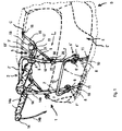
- Figure 1 is a perspective view of a luggage carrier, in the embodiment using configuration varying means comprising two screw tie rods and mounted on the rear door of a vehicle;
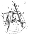
- Figure 2 is a side view of the luggage carrier in Figure 1;
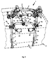
- Figure 3 is a perspective view of a luggage carrier, in the embodiment using configuration varying means comprising a single screw tie rod and mounted on the rear door of a vehicle;
- Figure 4 is a perspective view of a luggage carrier, like that of Figure 3, but with a different load supporting apparatus. The Figure 1 shows a
luggage carrier 1 mounted at the rear end of a vehicle D, represented by dashed line, and comprising aframe body 2 and afurther frame body 3. Theframe body 2 comprises a U-shaped portion 2', whose two ends extend over twoarms 7, each of which is provided with anextractable portion 8, provided with throughholes 9; once theluggage carrier 1 has been assembled, the U-shaped portion 2' shows thearms 7 turned downwards; between the U-shaped portion 2' and thearms 7 there is defined an obtuse angle G, not shown. The U-shaped portion 2' contains, near each one of its parallel sides, ahinge 5 with a possible clutch 4, the latter comprising a pair of discs and aknob 6 suitable for tightening a disc against the opposed disc. Thehinge 5 is interposed between theframe body 2 and thefurther frame body 3, and saidhinge 5 enables said frame bodies to be angularly adjusted each other. - The
extractable portion 8 can be received for a longer or shorter portion of its length into thearm 7 and can be fixed at the preset position by means of a bolt, not shown, suitable for being positioned at one of the throughholes 9. Thus, the length of everyarm 7 can be changed and in particular can be made suitable for being mounted on portions of the vehicle that, due to their extend, would be otherwise unreachable. - The
extractable portion 8 further comprises ananchoring appendage 10, terminating with acurved end 11 suitable for coupling with a bottom edge E' of the rear door E or a boot lid, not shown, of the vehicle D. - Near the ends of the
arms 7 adjacent to the rear bumper (not shown) of the vehicle D, there is placed a C-shaped element 12, arranged so as to have its longer rectilinear portion facing in the opposed direction with respect to the rear door E. The C-shaped element 12 engages with each of thearms 7 by means of a further hinge 5', comprising a further clutch 4' and a further knob 6'. The hinge 5' enables the C-shaped element 12 to be moved from a retracted position F to an extended position F', represented by a dashed line. That enables to prevent that a particularly voluminous object mounted on the luggage carrier, for example a bicycle, can accidentally hit and then damage the surface of the rear door E or of the rear bumper, not shown, of the vehicle D. - The
further frame body 3, as depicted in the Figures 1 to 3, shows a further U-shaped portion 3', whose two ends continue to two brackets 13', through twocurved portions 13. Each of the brackets 13' defines with the U-shaped portion 3' a further obtuse angle G', not shown. Each of the brackets 13' further contains a set ofgrooves 14a, suitable for being used advantageously as arack 14 whereon bicycles, having frame provided with central crossbar, can be received. With therack 14 there is associated a tighteningtape 14b suitable for holding in position the frame crossbar, received in everygroove 14a. - The
hinges 5 lie arranged at the intersection between the two portions of thefurther frame body 3 that are contained between the twocurved sections 13 and the tworacks 14. - The
further frame body 3 accommodates in its further U-shaped portion 3' at least aresting element 15, preferably in form of resilient cylinder having smooth surface; by means of theresting element 15 thefurther frame body 3 can be applied on the read door E without damaging the external surface of the latter. - Near the border between the further U-shaped portion 3' and each one of the bracket 13', an
elastic belt 16 is fixed to thefurther frame body 3 by means of a bolt 17. A free end of theelastic belt 16 comprises a furthercurved end 18, suitable for anchoring on an upper edge C of the rear door E or the boot lid (not shown) of the vehicle D. - With reference to Figure 4, an embodiment of the
luggage carrier 1 is provided, wherein thefurther frame body 3a comprises anotherfurther U-shaped portion 3b extending, at both the ends, over an L-shaped loading element 27. Each one of the L-shaped loading elements 27 comprises avertical bar 28a and ahorizontal bar 28b, mutually connected at right angle. Each one of thevertical arms 28a engages with theframe body 2 by means of thehinge 5 previously described. The twohorizontal bars 28b receive a pair of profiledelements 29, orthogonally arranged with respect to saidhorizontal bars 28b and having a roughly C-shaped section. With such advantageous version of theluggage carrier 1 bicycles can also be transported with frame unprovided with central crossbar, such as for example the ladies' bicycles. - The
frame body 2 and thefurther frame body 3 are further connected by means of a configuration varying device L. With reference to Figure 1, such configuration varying device L comprises a pair ofscrew tie rods 19. Each one of thescrew tie rods 19 comprises an adjustingscrew 20 received into an internal thread orsleeve 21; the end of the adjustingscrew 20, lying outside thesleeve 21, is further connected to aknob 22. - The end of each
screw tie rod 19 comprising theknob 22 is connected with theframe body 2 near thearm 7 at its own side. The end of thescrew tie rod 19 opposing that one comprising theknob 22 is connected with thefurther frame body 3 near the vertex of the obtuse angle G' defined between thecurved section 13 and the further U-shaped portion 3'. All said connections are obtained by means offurther bolts 30. In theluggage carrier 1 so assembled, an angle H results included between theframe body 2 and thefurther frame body 3. - By acting on the
knobs 22 of the configuration varying device L (see Figure 2) and then on the adjustingscrew 20, the configuration of theluggage carrier 1 can be varied so as to be brought from any open starting position M', indicated by means of a dashed line, to a mounting position M, indicated by means of a full line, or vice versa. - Thus, the
screw tie rod 19 is shortened, or respectively extended, so as to transform the angle H, into a further angle H', respectively smaller or greater than H. Such angular movement enables the configuration of theluggage carrier 1 to be varied, so as to be modified according to the size and the shape of the rear door E. In order to reduce the angle H to a further angle, not shown, smaller than H, it is sufficient to tighten the adjustingscrew 20, so that shortening of thescrew tie rod 19 is obtained. The possibility of properly fitting the configuration of theluggage carrier 1 to a plurality of shapes and sizes of vehicles results apparent by simply acting on thescrew tie rod 19. In addition, the arrangement of thescrew tie rod 19 is such to make saidscrew tie rod 19 easy to be handled by the user. - With reference to the Figures 3 and 4, it is possible to carry out the configuration adjusting device L so as to comprise a single
screw tie rod 19. The end of thescrew tie rod 19 opposed to theknob 22 is constrained near the middle region of the further U-shaped portion 3' of thefurther frame body 3 by means of a fork joint 23. The end of the adjustingscrew 20 comprising theknob 22 passes through the thickness of a further C-shapedelement 24, oriented so as to have the longer rectilinear side bordering the rear door E and comprising twoend segments 25, each one accommodating a supportingelement 26, implemented in a similar manner as the restingelements 15 previously described. - The
end segments 25 operate so as to maintain the load in a stable position during the motion of the vehicle D and to prevent the accidental contact thereof with the external surface of the rear door E.The supporting elements 26 prevent the occurrence of possible damages for the transported objects. The further C-shapedelement 24 is connected with thearms 7 of therod element 2 by means of a pair of furtherother hinges 5a, each of which comprises a furtherother knob 6a and a further other clutch 4a. With reference to the Figure 4, in the version of theluggage carrier 1 equipped by using thefurther frame body 3a, the further C-shapedelement 24 is replaced by another further C-shapedelement 24a. Such another further C-shapedelement 24a is unprovided withend segments 25 and further supportingelements 26, since the load accommodated on theluggage carrier 1 is firmly positioned on the L-shapedelement 27 included in the otherfurther frame body 3a, and such positioning prevents per se the contact of the load with the external surface of the rear door E of the vehicle D.
Claims (40)
- Apparatus for transporting loads, suitable for being mounted on a vehicle (D), comprising first frame body means (2) and second frame body means (3) that are mutually coupled by means of hinge means (5) and are arranged for being associated with opposed edges (C, E') of a portion (E) of a vehicle (D), configuration varying means (L) interconnecting said first frame body means (2) and said second frame body means (3) and arranged for varying the mutual angular position of said first frame body means (2) and said second frame body means (3) so as to enable a stable anchoring to said vehicle (D), characterized in that said configuration varying means (L) is positioned at a fixed distance from said hinge means (5) so that, by acting on said configuration varying means (L), it is possible to reduce, or to increase, an angle (H) defined between said first frame body means (2) and said second frame body means (3) when said apparatus is mounted on, or respectively removed from, said vehicle (D).
- Apparatus according to claim 1, wherein said configuration varying means (L) comprises tie rod means (19).
- Apparatus according to claim 2, wherein said tie rod means (19) comprises a single tie rod (19) arranged in intermediate position with respect to said first frame body means (2).
- Apparatus according to claim 3, wherein said single tie rod (19) is arranged so as to pass through C-shaped load spacing means (24) associated with said first frame body means (2).
- Apparatus according to any one of claims 2 to 4, wherein said tie rod means (19) comprises a pair of tie rod means (19) laterally arranged with respect to said first frame body means (2).
- Apparatus according to claim 2, wherein said tie rod means (19) comprises screw means (20) supported to said first frame body means (2), suitable for being manually actuated, and engaged with internal thread means (21) supported to said second frame body means (3).
- Apparatus according to any preceding claim, wherein said second frame body means (3) comprises an U-shaped portion (3'), each end of which extends to a corresponding bracket means (13') through a curved portion (13).
- Apparatus according to claim 7, wherein rack means (14) is obtained in said bracket means (13').
- Apparatus according to claim 6, wherein in said second frame body means (3) a further U-shaped portion (3b) is provided, each free end of which extends to L-shaped loading means (27) comprising vertical bar means (28a) and horizontal bar means (28b) that are mutually connected at an angle.
- Apparatus according to claim 9, wherein said horizontal bar means (28b) carries profiled means (29), transversally arranged with respect to said horizontal bar means (28b).
- Apparatus according to any preceding claim, wherein said first frame body means (2) comprises arm means (7).
- Apparatus according to any preceding claim, wherein said arm means (7) comprises telescopic portion means (8).
- Apparatus according to claim 11, or 12, wherein said arm means (7) supports, in adjustable manner, end regions of C-shaped load spacing means (12).
- Apparatus for transporting loads, suitable for being mounted on a vehicle (D), comprising first frame body means (2) and second frame body means (3) that are mutually coupled by means of hinge means (5) and are arranged for being associated with opposed edges (C, E') of a portion (E) of a vehicle (D), as well as configuration varying means (L) interconnecting said first frame body means (2) and said second frame body means (3) and arranged for varying the mutual angular position of said first frame body means (2) and said second frame body means (3) so as to enable a stable anchoring to said vehicle (D).
- Apparatus according to claim 14, wherein said first frame body means (2) and said second frame body means (3) form an integral body with load supporting means (14; 27) .
- Apparatus for transporting loads, suitable for being mounted on a vehicle, comprising frame body means (2, 3) that is arranged for being associated with opposed edges (C, E') of a portion of a vehicle (D), load supporting means (14; 27) associated with said frame body means (2, 3), characterized in that, said frame body means (2, 3) forms an integral body with said load supporting means (14; 27) .
- Apparatus according to claim 16, wherein said frame body means (2, 3) comprises first frame body means (2) and second frame body means (3) mutually interconnected by hinge means (5).
- Apparatus according to claim 17, wherein said first frame body means (2) and said second frame body means (3) are interconnected by configuration varying means (L) arranged for varying the mutual angular position of said first frame body means (2) and said second frame body means (3) so as to enable a stable anchoring to said vehicle (D).
- Apparatus according to claim 17, or 18, or 15, wherein said load supporting means (14; 27) is defined on extensions of said second frame body means (3) beyond said hinge means (5).
- Apparatus according to claim 14, or 15, or according to any of claims 17 to 19, wherein said first frame body means (2) comprises a U-shaped portion (2').
- Apparatus according to claim 20, wherein said U-shaped portion (2') extends over arm means (7).
- Apparatus according to claim 21, wherein said U-shaped portion (2') and said arm means (7) are arranged so as to define an obtuse angle (G).
- Apparatus according to claim 21, or 22, wherein said arm means (7) terminates with end anchoring appendix means (10) .
- Apparatus according to any of claims 21 to 23, wherein said arm means (7) comprises telescopic portion means (8) .
- Apparatus according to any of claims 21 to 24, wherein said arm means (7) supports, in adjustable manner, end regions of C-shaped load spacing means (12).
- Apparatus according to claim 14, or 15, or any of claims 17 to 25, wherein said second frame body means (3) comprises a further U-shaped portion (3').
- Apparatus according to claim 26, wherein said further U-shaped portion (3') comprises resting means (15) of shockproof material.
- Apparatus according to claim 26 or 27, as appended to claim 15, or from any of claims 17 to 25, comprising, in said load supporting means (14; 27), bracket means (13') arranged on the extension of said further U-shaped portion (3').
- Apparatus according to claim 28, wherein said bracket means (13') and said further U-shaped portion (3') are arranged so as to define a further obtuse angle (G').
- Apparatus according to claim 28, or 29, wherein said bracket means (13') accommodate rack means (14).
- Apparatus according to claim 28, or 29, wherein said bracket means (13') extends over L-shaped loading means (27), comprising vertical bar means (28a) and horizontal bar means (28b), mutually connected at an angle.
- Apparatus according to claim 31, wherein said horizontal bar means (28b) accommodates profiled means (29), transversally arranged with respect to said horizontal bar means (28b).
- Apparatus according to any of claims 14, or 15, or any of claims 17 to 32, wherein said hinge means (5) incorporates clutch blocking means (4).
- Apparatus according to claim 14, or 15, or any of claims 18 to 33, wherein said configuration varying means (L) comprises tie rod means (19).
- Apparatus according to claim 34, wherein said tie rod means (19) comprises a single tie rod (19) arranged in intermediate position with respect to said first frame body means (2).
- Apparatus according to claim 35, wherein said tie rod (19) is arranged so as to pass through a further C-shaped load spacing means (24) associated with said first frame body means (2).
- Apparatus according to any one of claims 34 to 36, wherein said tie rod means (19) comprises a pair of tie rod means (19) laterally arranged with respect to said first frame body means (2).
- Apparatus according to any one of claims 34 to 37, wherein said tie rod means (19) comprises screw means (20) supported to said first frame body means (2), suitable for being manually actuated, and engaged with internal thread means (21) supported to said second frame body means (3).
- Apparatus according to claim 36, or according to claim 37, or 38, as appended to claim 36, wherein said further C-shaped load spacing means (24) comprises supporting means (26) of shockproof material, arranged near end regions of said further C-shaped load spacing means (24).
- Apparatus according to any one of claims 28 to 39, wherein a curved portion (13) is comprised between said bracket means (13') and each end of said further U-shaped portion (3').
Applications Claiming Priority (2)
| Application Number | Priority Date | Filing Date | Title |
|---|---|---|---|
| IT2002MO000051A ITMO20020051A1 (en) | 2002-02-28 | 2002-02-28 | LUGGAGE RACK FOR VEHICLES |
| EP03706570A EP1478550B1 (en) | 2002-02-28 | 2003-02-25 | Luggage carrier for vehicle |
Related Parent Applications (1)
| Application Number | Title | Priority Date | Filing Date |
|---|---|---|---|
| EP03706570A Division EP1478550B1 (en) | 2002-02-28 | 2003-02-25 | Luggage carrier for vehicle |
Publications (3)
| Publication Number | Publication Date |
|---|---|
| EP1679231A2 true EP1679231A2 (en) | 2006-07-12 |
| EP1679231A3 EP1679231A3 (en) | 2006-08-30 |
| EP1679231B1 EP1679231B1 (en) | 2007-01-03 |
Family
ID=11450965
Family Applications (2)
| Application Number | Title | Priority Date | Filing Date |
|---|---|---|---|
| EP03706570A Revoked EP1478550B1 (en) | 2002-02-28 | 2003-02-25 | Luggage carrier for vehicle |
| EP05109802A Expired - Lifetime EP1679231B1 (en) | 2002-02-28 | 2003-02-25 | Luggage carrier for vehicle |
Family Applications Before (1)
| Application Number | Title | Priority Date | Filing Date |
|---|---|---|---|
| EP03706570A Revoked EP1478550B1 (en) | 2002-02-28 | 2003-02-25 | Luggage carrier for vehicle |
Country Status (6)
| Country | Link |
|---|---|
| EP (2) | EP1478550B1 (en) |
| AT (2) | ATE350243T1 (en) |
| AU (1) | AU2003208758A1 (en) |
| DE (2) | DE60311018T2 (en) |
| IT (1) | ITMO20020051A1 (en) |
| WO (1) | WO2003072396A1 (en) |
Families Citing this family (1)
| Publication number | Priority date | Publication date | Assignee | Title |
|---|---|---|---|---|
| ITMO20020231A1 (en) * | 2002-08-09 | 2004-02-10 | Menabo S R L Flli | LUGGAGE RACK FOR VEHICLES. |
Family Cites Families (7)
| Publication number | Priority date | Publication date | Assignee | Title |
|---|---|---|---|---|
| US3710999A (en) * | 1970-11-05 | 1973-01-16 | R Allen | Automobile carrier |
| US4336897A (en) | 1980-12-03 | 1982-06-29 | Luck Arthur J | Rack for bicycles |
| US4428516A (en) * | 1982-01-21 | 1984-01-31 | Allen Richard A | Collapsable bicycle carrier |
| FR2668435B1 (en) * | 1990-10-26 | 1995-05-12 | Mottez Sa | CAR BICYCLE CARRIER FOR FIXING TO THE BACK OF A VEHICLE TO ENSURE THE TRANSPORT OF A BICYCLE. |
| DE9407519U1 (en) * | 1994-05-06 | 1994-06-23 | Eufab Handelsgesellschaft für Auto- und Zweiradzubehör mbH, 42327 Wuppertal | Rear load carrier |
| US5702040A (en) | 1994-12-09 | 1997-12-30 | Hedeen; Nils E. | Bicycle carrier |
| FR2782966B1 (en) * | 1998-09-09 | 2000-10-13 | Automaxi Ind Sa | DEVICE FOR FIXING A BIKE CARRIER TO THE BACK OF A MOTOR VEHICLE |
-
2002
- 2002-02-28 IT IT2002MO000051A patent/ITMO20020051A1/en unknown
-
2003
- 2003-02-25 DE DE60311018T patent/DE60311018T2/en not_active Expired - Fee Related
- 2003-02-25 DE DE60305161T patent/DE60305161T2/en not_active Revoked
- 2003-02-25 AT AT05109802T patent/ATE350243T1/en not_active IP Right Cessation
- 2003-02-25 EP EP03706570A patent/EP1478550B1/en not_active Revoked
- 2003-02-25 EP EP05109802A patent/EP1679231B1/en not_active Expired - Lifetime
- 2003-02-25 AT AT03706570T patent/ATE325727T1/en not_active IP Right Cessation
- 2003-02-25 WO PCT/EP2003/001903 patent/WO2003072396A1/en not_active Ceased
- 2003-02-25 AU AU2003208758A patent/AU2003208758A1/en not_active Abandoned
Also Published As
| Publication number | Publication date |
|---|---|
| EP1679231B1 (en) | 2007-01-03 |
| ATE350243T1 (en) | 2007-01-15 |
| WO2003072396A1 (en) | 2003-09-04 |
| EP1478550A1 (en) | 2004-11-24 |
| EP1478550B1 (en) | 2006-05-10 |
| DE60305161T2 (en) | 2006-09-28 |
| DE60311018T2 (en) | 2007-04-19 |
| ATE325727T1 (en) | 2006-06-15 |
| AU2003208758A1 (en) | 2003-09-09 |
| EP1679231A3 (en) | 2006-08-30 |
| DE60311018D1 (en) | 2007-02-15 |
| ITMO20020051A1 (en) | 2003-08-28 |
| ITMO20020051A0 (en) | 2002-02-28 |
| DE60305161D1 (en) | 2006-06-14 |
Similar Documents
| Publication | Publication Date | Title |
|---|---|---|
| EP0563463B1 (en) | A device for loading, unloading and carrying bicycles on the roof of motor vehicles provided with a pair of carrier rails | |
| US11503935B2 (en) | Adjustable over-the-door hooks and racks | |
| US3877622A (en) | Foldable bicycle rack | |
| US5373978A (en) | Carrier for sporting goods | |
| US8322583B2 (en) | Detachable collapsible bicycle basket | |
| US4875608A (en) | Vehicle mounted foldable bicycle carrier | |
| EP0717686B1 (en) | Article carrier | |
| US4702401A (en) | Bicycle support device | |
| US5520316A (en) | Storage rack for automobile trunks | |
| US4116341A (en) | Device for storing bicycles in a building | |
| US6638001B1 (en) | Game lifting apparatus | |
| US6691959B1 (en) | Refuse bag holder | |
| WO2011063254A1 (en) | Trunk mounted bike carrier | |
| CA2166746A1 (en) | Adjustable ironing board assembly | |
| US5312077A (en) | Mounting device | |
| US4697776A (en) | Support frame for a display carton | |
| EP1679231B1 (en) | Luggage carrier for vehicle | |
| US6039521A (en) | Truck bed enclosure attachment posts | |
| WO1997011864A1 (en) | A device for vehicle-mounted load-carriers | |
| EP1534558B1 (en) | Load carrier for vehicles | |
| NL9200779A (en) | CARRIER ELEMENT FOR A HINGE FRAME. | |
| EP0433495A1 (en) | Adjustable bar for luggage racks, ski racks, anything carrying racks and the like | |
| US5634578A (en) | Load clamp for bicycle rack | |
| GB2278819A (en) | Carriers | |
| NL1034508C2 (en) | Pannier provided with a hook assembly. |
Legal Events
| Date | Code | Title | Description |
|---|---|---|---|
| PUAI | Public reference made under article 153(3) epc to a published international application that has entered the european phase |
Free format text: ORIGINAL CODE: 0009012 |
|
| 17P | Request for examination filed |
Effective date: 20051020 |
|
| AC | Divisional application: reference to earlier application |
Ref document number: 1478550 Country of ref document: EP Kind code of ref document: P |
|
| AK | Designated contracting states |
Kind code of ref document: A2 Designated state(s): AT BE BG CH CY CZ DE DK EE ES FI FR GB GR HU IE IT LI LU MC NL PT SE SI SK TR |
|
| PUAL | Search report despatched |
Free format text: ORIGINAL CODE: 0009013 |
|
| GRAP | Despatch of communication of intention to grant a patent |
Free format text: ORIGINAL CODE: EPIDOSNIGR1 |
|
| AK | Designated contracting states |
Kind code of ref document: A3 Designated state(s): AT BE BG CH CY CZ DE DK EE ES FI FR GB GR HU IE IT LI LU MC NL PT SE SI SK TR |
|
| GRAS | Grant fee paid |
Free format text: ORIGINAL CODE: EPIDOSNIGR3 |
|
| GRAA | (expected) grant |
Free format text: ORIGINAL CODE: 0009210 |
|
| AC | Divisional application: reference to earlier application |
Ref document number: 1478550 Country of ref document: EP Kind code of ref document: P |
|
| AK | Designated contracting states |
Kind code of ref document: B1 Designated state(s): AT BE BG CH CY CZ DE DK EE ES FI FR GB GR HU IE IT LI LU MC NL PT SE SI SK TR |
|
| PG25 | Lapsed in a contracting state [announced via postgrant information from national office to epo] |
Ref country code: DK Free format text: LAPSE BECAUSE OF FAILURE TO SUBMIT A TRANSLATION OF THE DESCRIPTION OR TO PAY THE FEE WITHIN THE PRESCRIBED TIME-LIMIT Effective date: 20070103 Ref country code: NL Free format text: LAPSE BECAUSE OF FAILURE TO SUBMIT A TRANSLATION OF THE DESCRIPTION OR TO PAY THE FEE WITHIN THE PRESCRIBED TIME-LIMIT Effective date: 20070103 Ref country code: LI Free format text: LAPSE BECAUSE OF FAILURE TO SUBMIT A TRANSLATION OF THE DESCRIPTION OR TO PAY THE FEE WITHIN THE PRESCRIBED TIME-LIMIT Effective date: 20070103 Ref country code: FI Free format text: LAPSE BECAUSE OF FAILURE TO SUBMIT A TRANSLATION OF THE DESCRIPTION OR TO PAY THE FEE WITHIN THE PRESCRIBED TIME-LIMIT Effective date: 20070103 Ref country code: AT Free format text: LAPSE BECAUSE OF FAILURE TO SUBMIT A TRANSLATION OF THE DESCRIPTION OR TO PAY THE FEE WITHIN THE PRESCRIBED TIME-LIMIT Effective date: 20070103 Ref country code: CH Free format text: LAPSE BECAUSE OF FAILURE TO SUBMIT A TRANSLATION OF THE DESCRIPTION OR TO PAY THE FEE WITHIN THE PRESCRIBED TIME-LIMIT Effective date: 20070103 Ref country code: SI Free format text: LAPSE BECAUSE OF FAILURE TO SUBMIT A TRANSLATION OF THE DESCRIPTION OR TO PAY THE FEE WITHIN THE PRESCRIBED TIME-LIMIT Effective date: 20070103 |
|
| REG | Reference to a national code |
Ref country code: GB Ref legal event code: FG4D |
|
| REF | Corresponds to: |
Ref document number: 60311018 Country of ref document: DE Date of ref document: 20070215 Kind code of ref document: P |
|
| REG | Reference to a national code |
Ref country code: IE Ref legal event code: FG4D |
|
| PG25 | Lapsed in a contracting state [announced via postgrant information from national office to epo] |
Ref country code: MC Free format text: LAPSE BECAUSE OF NON-PAYMENT OF DUE FEES Effective date: 20070228 |
|
| PG25 | Lapsed in a contracting state [announced via postgrant information from national office to epo] |
Ref country code: BG Free format text: LAPSE BECAUSE OF FAILURE TO SUBMIT A TRANSLATION OF THE DESCRIPTION OR TO PAY THE FEE WITHIN THE PRESCRIBED TIME-LIMIT Effective date: 20070403 |
|
| PG25 | Lapsed in a contracting state [announced via postgrant information from national office to epo] |
Ref country code: ES Free format text: LAPSE BECAUSE OF FAILURE TO SUBMIT A TRANSLATION OF THE DESCRIPTION OR TO PAY THE FEE WITHIN THE PRESCRIBED TIME-LIMIT Effective date: 20070414 |
|
| REG | Reference to a national code |
Ref country code: SE Ref legal event code: TRGR |
|
| AKX | Designation fees paid |
Designated state(s): AT BE BG CH CY CZ DE DK EE ES FI FR GB GR HU IE IT LI LU MC NL PT SE SI SK TR |
|
| PG25 | Lapsed in a contracting state [announced via postgrant information from national office to epo] |
Ref country code: PT Free format text: LAPSE BECAUSE OF FAILURE TO SUBMIT A TRANSLATION OF THE DESCRIPTION OR TO PAY THE FEE WITHIN THE PRESCRIBED TIME-LIMIT Effective date: 20070604 |
|
| NLV1 | Nl: lapsed or annulled due to failure to fulfill the requirements of art. 29p and 29m of the patents act | ||
| REG | Reference to a national code |
Ref country code: CH Ref legal event code: PL |
|
| ET | Fr: translation filed | ||
| PLBE | No opposition filed within time limit |
Free format text: ORIGINAL CODE: 0009261 |
|
| STAA | Information on the status of an ep patent application or granted ep patent |
Free format text: STATUS: NO OPPOSITION FILED WITHIN TIME LIMIT |
|
| PG25 | Lapsed in a contracting state [announced via postgrant information from national office to epo] |
Ref country code: SK Free format text: LAPSE BECAUSE OF FAILURE TO SUBMIT A TRANSLATION OF THE DESCRIPTION OR TO PAY THE FEE WITHIN THE PRESCRIBED TIME-LIMIT Effective date: 20070103 |
|
| 26N | No opposition filed |
Effective date: 20071005 |
|
| GBPC | Gb: european patent ceased through non-payment of renewal fee |
Effective date: 20070403 |
|
| PG25 | Lapsed in a contracting state [announced via postgrant information from national office to epo] |
Ref country code: BE Free format text: LAPSE BECAUSE OF FAILURE TO SUBMIT A TRANSLATION OF THE DESCRIPTION OR TO PAY THE FEE WITHIN THE PRESCRIBED TIME-LIMIT Effective date: 20070103 Ref country code: CZ Free format text: LAPSE BECAUSE OF FAILURE TO SUBMIT A TRANSLATION OF THE DESCRIPTION OR TO PAY THE FEE WITHIN THE PRESCRIBED TIME-LIMIT Effective date: 20070103 |
|
| PG25 | Lapsed in a contracting state [announced via postgrant information from national office to epo] |
Ref country code: IE Free format text: LAPSE BECAUSE OF NON-PAYMENT OF DUE FEES Effective date: 20070226 |
|
| PG25 | Lapsed in a contracting state [announced via postgrant information from national office to epo] |
Ref country code: GB Free format text: LAPSE BECAUSE OF NON-PAYMENT OF DUE FEES Effective date: 20070403 Ref country code: GR Free format text: LAPSE BECAUSE OF FAILURE TO SUBMIT A TRANSLATION OF THE DESCRIPTION OR TO PAY THE FEE WITHIN THE PRESCRIBED TIME-LIMIT Effective date: 20070404 |
|
| PG25 | Lapsed in a contracting state [announced via postgrant information from national office to epo] |
Ref country code: EE Free format text: LAPSE BECAUSE OF FAILURE TO SUBMIT A TRANSLATION OF THE DESCRIPTION OR TO PAY THE FEE WITHIN THE PRESCRIBED TIME-LIMIT Effective date: 20070103 |
|
| PGFP | Annual fee paid to national office [announced via postgrant information from national office to epo] |
Ref country code: DE Payment date: 20090227 Year of fee payment: 7 |
|
| PG25 | Lapsed in a contracting state [announced via postgrant information from national office to epo] |
Ref country code: CY Free format text: LAPSE BECAUSE OF FAILURE TO SUBMIT A TRANSLATION OF THE DESCRIPTION OR TO PAY THE FEE WITHIN THE PRESCRIBED TIME-LIMIT Effective date: 20070103 |
|
| PG25 | Lapsed in a contracting state [announced via postgrant information from national office to epo] |
Ref country code: IT Free format text: LAPSE BECAUSE OF NON-PAYMENT OF DUE FEES Effective date: 20080225 Ref country code: LU Free format text: LAPSE BECAUSE OF NON-PAYMENT OF DUE FEES Effective date: 20070225 |
|
| PGFP | Annual fee paid to national office [announced via postgrant information from national office to epo] |
Ref country code: SE Payment date: 20090126 Year of fee payment: 7 |
|
| PG25 | Lapsed in a contracting state [announced via postgrant information from national office to epo] |
Ref country code: HU Free format text: LAPSE BECAUSE OF FAILURE TO SUBMIT A TRANSLATION OF THE DESCRIPTION OR TO PAY THE FEE WITHIN THE PRESCRIBED TIME-LIMIT Effective date: 20070704 Ref country code: TR Free format text: LAPSE BECAUSE OF FAILURE TO SUBMIT A TRANSLATION OF THE DESCRIPTION OR TO PAY THE FEE WITHIN THE PRESCRIBED TIME-LIMIT Effective date: 20070103 |
|
| PGFP | Annual fee paid to national office [announced via postgrant information from national office to epo] |
Ref country code: FR Payment date: 20090226 Year of fee payment: 7 |
|
| EUG | Se: european patent has lapsed | ||
| REG | Reference to a national code |
Ref country code: FR Ref legal event code: ST Effective date: 20101029 |
|
| PG25 | Lapsed in a contracting state [announced via postgrant information from national office to epo] |
Ref country code: FR Free format text: LAPSE BECAUSE OF NON-PAYMENT OF DUE FEES Effective date: 20100301 |
|
| PG25 | Lapsed in a contracting state [announced via postgrant information from national office to epo] |
Ref country code: DE Free format text: LAPSE BECAUSE OF NON-PAYMENT OF DUE FEES Effective date: 20100901 |
|
| PGFP | Annual fee paid to national office [announced via postgrant information from national office to epo] |
Ref country code: IT Payment date: 20090224 Year of fee payment: 7 |
|
| PGRI | Patent reinstated in contracting state [announced from national office to epo] |
Ref country code: IT Effective date: 20110616 |
|
| PG25 | Lapsed in a contracting state [announced via postgrant information from national office to epo] |
Ref country code: SE Free format text: LAPSE BECAUSE OF NON-PAYMENT OF DUE FEES Effective date: 20100226 |
|
| PGRI | Patent reinstated in contracting state [announced from national office to epo] |
Ref country code: IT Effective date: 20110616 |