EP1679252A1 - Liaison structurelle pour un chassis - Google Patents
Liaison structurelle pour un chassis Download PDFInfo
- Publication number
- EP1679252A1 EP1679252A1 EP05100064A EP05100064A EP1679252A1 EP 1679252 A1 EP1679252 A1 EP 1679252A1 EP 05100064 A EP05100064 A EP 05100064A EP 05100064 A EP05100064 A EP 05100064A EP 1679252 A1 EP1679252 A1 EP 1679252A1
- Authority
- EP
- European Patent Office
- Prior art keywords
- cross member
- connection
- arrangement according
- attachment
- region
- Prior art date
- Legal status (The legal status is an assumption and is not a legal conclusion. Google has not performed a legal analysis and makes no representation as to the accuracy of the status listed.)
- Withdrawn
Links
- 239000000725 suspension Substances 0.000 claims description 9
- 239000000969 carrier Substances 0.000 claims description 8
- 150000001875 compounds Chemical class 0.000 claims description 4
- 238000007373 indentation Methods 0.000 description 3
- 230000003014 reinforcing effect Effects 0.000 description 3
- 230000000712 assembly Effects 0.000 description 2
- 238000000429 assembly Methods 0.000 description 2
- 239000011324 bead Substances 0.000 description 2
- 238000004519 manufacturing process Methods 0.000 description 2
- 238000003466 welding Methods 0.000 description 2
- 229910000831 Steel Inorganic materials 0.000 description 1
- 230000006978 adaptation Effects 0.000 description 1
- 230000001419 dependent effect Effects 0.000 description 1
- 238000006073 displacement reaction Methods 0.000 description 1
- 238000005553 drilling Methods 0.000 description 1
- 239000002184 metal Substances 0.000 description 1
- 230000002787 reinforcement Effects 0.000 description 1
- 230000000284 resting effect Effects 0.000 description 1
- 239000010959 steel Substances 0.000 description 1
Images



Classifications
-
- B—PERFORMING OPERATIONS; TRANSPORTING
- B62—LAND VEHICLES FOR TRAVELLING OTHERWISE THAN ON RAILS
- B62D—MOTOR VEHICLES; TRAILERS
- B62D21/00—Understructures, i.e. chassis frame on which a vehicle body may be mounted
- B62D21/11—Understructures, i.e. chassis frame on which a vehicle body may be mounted with resilient means for suspension, e.g. of wheels or engine; sub-frames for mounting engine or suspensions
Definitions
- the invention relates to a body joint assembly with a longitudinal beam and with a cross member, which are connected to each other and abut each other in the region of the compound.
- Body joint assemblies of the above type are common in motor vehicles, especially passenger cars (PKW) and therefore known. They usually include laterally arranged and extending in the longitudinal direction of the vehicle side members, which are connected via approximately transversely thereto extending cross member. These are usually welded together at the joints where the beams abut each other.
- a motor vehicle rear frame in which two longitudinal members are connected to one another by a rear axle cross member.
- a respective end face partially closing elbow is welded at each end of the cross member, which in turn is welded to the outside of the longitudinal member.
- a reinforcing sheet is welded below the connecting gap against the undersides of the beams.
- DE 195 07 767 C2 discloses a vehicle chassis subframe mounting structure in which a cross member is arranged between lateral side members, wherein an additional carrier is fixed to the connecting portions between the longitudinal members and cross member.
- the cross member and the respective side member adjoin each other without overlapping.
- a nut member for fixing a subframe for other components is arranged.
- a cross member as part of a motor vehicle floor group is known from DE 100 22 916 A1. This has on both sides in the connection area depending on a mounting area for screwing a rear axle unit and an adjacent spring receiving area for fixing a coil spring.
- a stiffening structure is provided in the connection area formed by box-shaped interleaved steel sheets.
- the strength of body joint assemblies in the field of seat and / or seat belt fasteners in the ground area of importance since they are exposed to very high loads in the event of a crash.
- the seat and / or seat belt fasteners are bolted to the vehicle floor, which is reinforced with additional sheets.
- the reinforcing plates can in turn be spot-welded to the rear axle cross member, so that the occurring forces can be distributed to the longitudinal members via the axle cross member.
- the connection point or connection arrangement of the cross member with the respective side member is heavily loaded.
- welding points may break between the cross member and the side member.
- connection points or connection arrangements In bodies and therefore also in their connection arrangements, there is thus a desire to carry them out with a high strength of the connection points or connection arrangements in spite of simple and cost-effective production and low weight and high rigidity.
- the carriers in the region of the connection overlap one another and an attachment for a vehicle part is arranged in the overlapping region of the connection and thus engages one of the two carriers and at least bears against the other carrier, that the strength of the region of the connection through the made Attachment of the vehicle part is increased, it is possible to solidify the connection arrangement with simple and inexpensive production and low weight and high rigidity.
- the usually already existing attachment for a vehicle part is thus in the overlapping region of the compound the carrier relocates. This is achieved without additional reinforcement plates or reinforced components.
- longitudinal members are to be understood in the longitudinal direction of the vehicle-oriented carrier, in particular those of the bottom group of the body.
- the cross member is accordingly at an angle of about 90 ° thereto, so approximately transversely to aligned carrier such.
- B is an axle cross member.
- the angle in the region of the connection between the carriers can be in the order of about 60 to 120 °, depending on the design of the carrier in detail.
- crossbeams initially form a deviating from 90 ° angle only in the region of the connection to the longitudinal member, the overall alignment of the carrier to each other, however, is still approximately transversely or perpendicular to each other.
- the cross member overlaps the side rail.
- the cross member surrounds the longitudinal member so that it is "wound around" the longitudinal member, so that a particularly strong and at the same time rigid connection arrangement is achieved.
- the cross member is a seat cross member, a rear seat cross member, an axle cross member, a Schuachsquerthe or a subframe of the chassis or suspension suspension or a cross member.
- a seat cross member a rear seat cross member
- an axle cross member a Deutschenachsquerthe or a subframe of the chassis or suspension suspension or a cross member.
- a Deutschenachsquerthe a subframe of the chassis or suspension suspension or a cross member.
- B. in the subframe of a Achsquerliess or chassis is the case. These are particularly suitable because they are usually designed to be particularly stable.
- cross member seat and / or seat belt fasteners are arranged in a further embodiment.
- the force introduced in the event of a crash can be transmitted or distributed without interruption via the cross member to the longitudinal members and to the further vehicle part, which is fastened in the overlapping region of the connection.
- ECE 14 and ECE 17 test conditions there is no danger of tearing out (see above).
- vehicle part is part of the chassis so that these structurally stable vehicle parts absorb part of the introduced forces. It also reduces the displacement of the body panels under the ECE 14 and ECE 17 test conditions.
- the attachment passes through the side rail and is applied to the cross member or the attachment passes through both the longitudinal member and the cross member. These arrangements further increase the strength of the connection assembly and allow easy fixing of the attachment.
- the attachment is a sleeve which is preferably fixed in the upper of the two supports (usually the side members). Also, the sleeve can be supported at least on the lower support. It makes sense if the sleeve is a threaded sleeve, so that z. B. the chassis part can be attached by screwing.
- the chassis part is a part of the suspension chassis and screwed by means of attachment to the cross member and side member.
- FIGS. 1 and 2 a respective perspective view of a connecting arrangement of a passenger vehicle body designated as a whole by 1 in the region of a connection of a cross member 2 with a longitudinal member 3 from above or from below is shown.
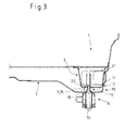
- Figures 3 and 4 show sections through the region of the connection with bolted axle suspension. It is understood that, although only one side of the cross member 2 is shown and will be described, the other side of the cross member 2 is constructed accordingly and the cross member 2 connects two laterally arranged side members 3 together.
- the cross member 2 is in this case a Wegachsquerany, which is constructed of an approximately U-shaped upwardly open plate.
- the cross member 2 comprises along the longitudinal sides in each case a bent-over edge 6.
- the cross member 2 further comprises beads 7 and indentations or bulges 8 for increasing the rigidity and strength and / or for adaptation to other vehicle parts, not shown.
- a seat and / or seat belt fastening plate 4 is welded to which any seat and / or seat belt fastenings can be made through a floor panel.
- the longitudinal member 3 is aligned approximately in the longitudinal direction of the vehicle and also has an approximately U-shaped cross section and along the longitudinal sides in each case a bent edge 9.
- the longitudinal beam 3 can also beads and indentations or bulges to increase the stiffness and strength and / or have to adapt to other not shown vehicle parts.
- the cross member 2 overlaps the longitudinal member 3, d. H. lies in Figure 1 (seen from above) with its edges 6 from below to this.
- the cross member and the side member thus overlap in the area of their connection.
- the cross member 2 is connected to the longitudinal member 3 in the usual way via welds.
- the cross member 2 engages around the side member 3 on its end face 10, thus resting against its outside 11 with a bent region 12.
- the cross member 2 jumps in the region of the connection to the longitudinal member 3 back or down, so that the upper edges of the edges 6, 9 of the two carriers 2, 3 form approximately a common plane for a floor panel.
- the connection arrangement 1 further comprises a fastening 5 for a vehicle part, which is arranged in the overlapping region of the connection.
- the vehicle part is a subframe 14 of the rear axle suspension, which is not shown for clarity.
- the attachment 5 is designed as a threaded sleeve 16, with which the subframe 14 is screwed by means of a corresponding threaded screw 15.
- the lower cross member 2 has a corresponding bore 13, as shown in particular in FIGS. 3 and 4.
- the threaded sleeve 16 is widened at the lower end 17, so that it is supported on the lower inner side 18 of the cross member 2 around the circumference of the bore 13 and may possibly be welded there. Above this, the threaded sleeve 16 has a threaded portion 19 for receiving the threaded screw 15.
- the threaded sleeve 16 extends upwardly and passes through a recess 20 provided in the underside of the longitudinal member 3. Above and inside the longitudinal member 3, the threaded sleeve 16 is fixed to a metal sheet 21 arranged between the side walls of the longitudinal member 3 , This can be z. B. done by welding.
- connection assembly 1 Due to the additional connection of the two carriers 2, 3 via the attachment 5 so the connection assembly 1 is amplified.
- the originating from the seat and / or seat belt fasteners forces on the mounting plates 4 to the cross member 2 and from there to the side member 3 and the attachment 5 or threaded sleeve 16 are also passed to the subframe 14 of the axle suspension.
Landscapes
- Engineering & Computer Science (AREA)
- Chemical & Material Sciences (AREA)
- Combustion & Propulsion (AREA)
- Transportation (AREA)
- Mechanical Engineering (AREA)
- Body Structure For Vehicles (AREA)
Priority Applications (1)
| Application Number | Priority Date | Filing Date | Title |
|---|---|---|---|
| EP05100064A EP1679252A1 (fr) | 2005-01-06 | 2005-01-06 | Liaison structurelle pour un chassis |
Applications Claiming Priority (1)
| Application Number | Priority Date | Filing Date | Title |
|---|---|---|---|
| EP05100064A EP1679252A1 (fr) | 2005-01-06 | 2005-01-06 | Liaison structurelle pour un chassis |
Publications (1)
| Publication Number | Publication Date |
|---|---|
| EP1679252A1 true EP1679252A1 (fr) | 2006-07-12 |
Family
ID=34938492
Family Applications (1)
| Application Number | Title | Priority Date | Filing Date |
|---|---|---|---|
| EP05100064A Withdrawn EP1679252A1 (fr) | 2005-01-06 | 2005-01-06 | Liaison structurelle pour un chassis |
Country Status (1)
| Country | Link |
|---|---|
| EP (1) | EP1679252A1 (fr) |
Cited By (3)
| Publication number | Priority date | Publication date | Assignee | Title |
|---|---|---|---|---|
| CN102530083A (zh) * | 2011-12-31 | 2012-07-04 | 重庆长安汽车股份有限公司 | 一种轿车下横梁焊接总成 |
| DE102015208898B3 (de) * | 2015-05-13 | 2016-08-25 | Volkswagen Aktiengesellschaft | Befestigungssystem und Achshilfsrahmen |
| CN112477986A (zh) * | 2020-11-27 | 2021-03-12 | 大运汽车股份有限公司 | 一种前副车架左后安装总成结构 |
Citations (4)
| Publication number | Priority date | Publication date | Assignee | Title |
|---|---|---|---|---|
| JPH06171553A (ja) * | 1992-12-04 | 1994-06-21 | Nissan Motor Co Ltd | 車体フロアのリアサスペンション取付部構造 |
| DE4329532A1 (de) * | 1993-06-01 | 1995-03-09 | Porsche Ag | Kraftfahrzeug |
| US20030160415A1 (en) * | 2002-02-22 | 2003-08-28 | Ki-Chang Kim | Rear suspension connecting part structure under the floor of a vehicle |
| EP1415896A2 (fr) * | 2002-11-01 | 2004-05-06 | Fuji Jukogyo Kabushiki Kaisha | Structure arrière de véhicule |
-
2005
- 2005-01-06 EP EP05100064A patent/EP1679252A1/fr not_active Withdrawn
Patent Citations (4)
| Publication number | Priority date | Publication date | Assignee | Title |
|---|---|---|---|---|
| JPH06171553A (ja) * | 1992-12-04 | 1994-06-21 | Nissan Motor Co Ltd | 車体フロアのリアサスペンション取付部構造 |
| DE4329532A1 (de) * | 1993-06-01 | 1995-03-09 | Porsche Ag | Kraftfahrzeug |
| US20030160415A1 (en) * | 2002-02-22 | 2003-08-28 | Ki-Chang Kim | Rear suspension connecting part structure under the floor of a vehicle |
| EP1415896A2 (fr) * | 2002-11-01 | 2004-05-06 | Fuji Jukogyo Kabushiki Kaisha | Structure arrière de véhicule |
Non-Patent Citations (1)
| Title |
|---|
| PATENT ABSTRACTS OF JAPAN vol. 018, no. 503 (M - 1677) 21 September 1994 (1994-09-21) * |
Cited By (3)
| Publication number | Priority date | Publication date | Assignee | Title |
|---|---|---|---|---|
| CN102530083A (zh) * | 2011-12-31 | 2012-07-04 | 重庆长安汽车股份有限公司 | 一种轿车下横梁焊接总成 |
| DE102015208898B3 (de) * | 2015-05-13 | 2016-08-25 | Volkswagen Aktiengesellschaft | Befestigungssystem und Achshilfsrahmen |
| CN112477986A (zh) * | 2020-11-27 | 2021-03-12 | 大运汽车股份有限公司 | 一种前副车架左后安装总成结构 |
Similar Documents
| Publication | Publication Date | Title |
|---|---|---|
| DE69708009T2 (de) | Fahrzeugkarosserie | |
| EP1744945B1 (fr) | Vehicule automobile | |
| EP2547574B1 (fr) | Élément avant d'un véhicule | |
| DE102011051481B4 (de) | Stoßfängeranordnung für ein Kraftfahrzeug | |
| DE602005003737T2 (de) | Fahrzeug-Unterboden- bzw- Unterbauaufbau bzw. -struktur | |
| DE102009050495B4 (de) | Hilfsrahmen | |
| DE102010034932A1 (de) | Kraftfahrzeugkarosserie mit strukturverstärkter Vorderrahmenanbindung | |
| DE102008015221A1 (de) | Aufbau eines hinteren Abschnitts einer Kraftfahrzeugkarosserie | |
| DE102010051256A1 (de) | Kraftfahrzeugkarosserie mit Verstärkungsstruktur | |
| DE102019207486A1 (de) | Karosseriebodenstruktur für ein Fahrzeug | |
| DE102016223216A1 (de) | Karosserie-Bodenstruktur für ein Fahrzeug | |
| DE102016209186B3 (de) | Karosseriestruktur für ein Kraftfahrzeug | |
| DE102019211108A1 (de) | Karosseriestruktur für ein elektrisch betriebenes Fahrzeug | |
| EP3959117B1 (fr) | Structure d'avant-corps de la carrosserie d'un véhicule | |
| EP0591715A2 (fr) | Véhicule utilitaire, en particulier camion avec cabine à l'avant | |
| EP1525133B1 (fr) | Structure de renfort de sol pour automobile | |
| DE102020129504A1 (de) | Fahrgestellkonstruktion für ein Nutzfahrzeug | |
| DE102011002964A1 (de) | Lagerung eines Querstabilisators an einem rahmenartigen Achsträger eines zweispurigen Fahrzeugs | |
| EP3239022A1 (fr) | Composite de plateforme | |
| DE102018004380B4 (de) | Verstärkungsteil | |
| DE102010049427A1 (de) | Querträgeranordnung, insbesondere Fersenblechanordnung in einer Fahrzeugkarosserie | |
| DE102019218697A1 (de) | Kraftfahrzeugkarosserie mit einem Stützelement und Kraftfahrzeug, umfassend die Fahrzeugkarosserie | |
| EP3348455B1 (fr) | Structure de support pour un véhicule utilitaire non entraîné | |
| DE102006057665B4 (de) | Rahmenartiger Achsträger für ein Kraftfahrzeug | |
| DE102008041501A1 (de) | Vorderbau für ein Fahrzeug |
Legal Events
| Date | Code | Title | Description |
|---|---|---|---|
| PUAI | Public reference made under article 153(3) epc to a published international application that has entered the european phase |
Free format text: ORIGINAL CODE: 0009012 |
|
| AK | Designated contracting states |
Kind code of ref document: A1 Designated state(s): AT BE BG CH CY CZ DE DK EE ES FI FR GB GR HU IE IS IT LI LT LU MC NL PL PT RO SE SI SK TR |
|
| AX | Request for extension of the european patent |
Extension state: AL BA HR LV MK YU |
|
| 17P | Request for examination filed |
Effective date: 20070112 |
|
| AKX | Designation fees paid |
Designated state(s): DE FR GB |
|
| 17Q | First examination report despatched |
Effective date: 20080711 |
|
| STAA | Information on the status of an ep patent application or granted ep patent |
Free format text: STATUS: THE APPLICATION IS DEEMED TO BE WITHDRAWN |
|
| 18D | Application deemed to be withdrawn |
Effective date: 20081122 |