EP1679267A2 - Plastikverschluss mit hervorragenden Dichtungs- und Entlüftungseigenschaften - Google Patents
Plastikverschluss mit hervorragenden Dichtungs- und Entlüftungseigenschaften Download PDFInfo
- Publication number
- EP1679267A2 EP1679267A2 EP05112068A EP05112068A EP1679267A2 EP 1679267 A2 EP1679267 A2 EP 1679267A2 EP 05112068 A EP05112068 A EP 05112068A EP 05112068 A EP05112068 A EP 05112068A EP 1679267 A2 EP1679267 A2 EP 1679267A2
- Authority
- EP
- European Patent Office
- Prior art keywords
- inner ring
- mouth
- plastic cap
- wall
- cap
- Prior art date
- Legal status (The legal status is an assumption and is not a legal conclusion. Google has not performed a legal analysis and makes no representation as to the accuracy of the status listed.)
- Granted
Links
Images





Classifications
-
- B—PERFORMING OPERATIONS; TRANSPORTING
- B65—CONVEYING; PACKING; STORING; HANDLING THIN OR FILAMENTARY MATERIAL
- B65D—CONTAINERS FOR STORAGE OR TRANSPORT OF ARTICLES OR MATERIALS, e.g. BAGS, BARRELS, BOTTLES, BOXES, CANS, CARTONS, CRATES, DRUMS, JARS, TANKS, HOPPERS, FORWARDING CONTAINERS; ACCESSORIES, CLOSURES, OR FITTINGS THEREFOR; PACKAGING ELEMENTS; PACKAGES
- B65D51/00—Closures not otherwise provided for
- B65D51/16—Closures not otherwise provided for with means for venting air or gas
- B65D51/1633—Closures not otherwise provided for with means for venting air or gas whereby venting occurs by automatic opening of the closure, container or other element
- B65D51/1661—Closures not otherwise provided for with means for venting air or gas whereby venting occurs by automatic opening of the closure, container or other element by means of a passage for the escape of gas between the closure and the lip of the container mouth
-
- B—PERFORMING OPERATIONS; TRANSPORTING
- B65—CONVEYING; PACKING; STORING; HANDLING THIN OR FILAMENTARY MATERIAL
- B65D—CONTAINERS FOR STORAGE OR TRANSPORT OF ARTICLES OR MATERIALS, e.g. BAGS, BARRELS, BOTTLES, BOXES, CANS, CARTONS, CRATES, DRUMS, JARS, TANKS, HOPPERS, FORWARDING CONTAINERS; ACCESSORIES, CLOSURES, OR FITTINGS THEREFOR; PACKAGING ELEMENTS; PACKAGES
- B65D41/00—Caps, e.g. crown caps or crown seals, i.e. members having parts arranged for engagement with the external periphery of a neck or wall defining a pouring opening or discharge aperture; Protective cap-like covers for closure members, e.g. decorative covers of metal foil or paper
- B65D41/02—Caps or cap-like covers without lines of weakness, tearing strips, tags, or like opening or removal devices
- B65D41/16—Snap-on caps or cap-like covers
-
- B—PERFORMING OPERATIONS; TRANSPORTING
- B65—CONVEYING; PACKING; STORING; HANDLING THIN OR FILAMENTARY MATERIAL
- B65D—CONTAINERS FOR STORAGE OR TRANSPORT OF ARTICLES OR MATERIALS, e.g. BAGS, BARRELS, BOTTLES, BOXES, CANS, CARTONS, CRATES, DRUMS, JARS, TANKS, HOPPERS, FORWARDING CONTAINERS; ACCESSORIES, CLOSURES, OR FITTINGS THEREFOR; PACKAGING ELEMENTS; PACKAGES
- B65D41/00—Caps, e.g. crown caps or crown seals, i.e. members having parts arranged for engagement with the external periphery of a neck or wall defining a pouring opening or discharge aperture; Protective cap-like covers for closure members, e.g. decorative covers of metal foil or paper
-
- B—PERFORMING OPERATIONS; TRANSPORTING
- B65—CONVEYING; PACKING; STORING; HANDLING THIN OR FILAMENTARY MATERIAL
- B65D—CONTAINERS FOR STORAGE OR TRANSPORT OF ARTICLES OR MATERIALS, e.g. BAGS, BARRELS, BOTTLES, BOXES, CANS, CARTONS, CRATES, DRUMS, JARS, TANKS, HOPPERS, FORWARDING CONTAINERS; ACCESSORIES, CLOSURES, OR FITTINGS THEREFOR; PACKAGING ELEMENTS; PACKAGES
- B65D41/00—Caps, e.g. crown caps or crown seals, i.e. members having parts arranged for engagement with the external periphery of a neck or wall defining a pouring opening or discharge aperture; Protective cap-like covers for closure members, e.g. decorative covers of metal foil or paper
- B65D41/32—Caps or cap-like covers with lines of weakness, tearing-strips, tags, or like opening or removal devices, e.g. to facilitate formation of pouring openings
- B65D41/325—Caps or cap-like covers with lines of weakness, tearing-strips, tags, or like opening or removal devices, e.g. to facilitate formation of pouring openings with integral internal sealing means
-
- B—PERFORMING OPERATIONS; TRANSPORTING
- B65—CONVEYING; PACKING; STORING; HANDLING THIN OR FILAMENTARY MATERIAL
- B65D—CONTAINERS FOR STORAGE OR TRANSPORT OF ARTICLES OR MATERIALS, e.g. BAGS, BARRELS, BOTTLES, BOXES, CANS, CARTONS, CRATES, DRUMS, JARS, TANKS, HOPPERS, FORWARDING CONTAINERS; ACCESSORIES, CLOSURES, OR FITTINGS THEREFOR; PACKAGING ELEMENTS; PACKAGES
- B65D41/00—Caps, e.g. crown caps or crown seals, i.e. members having parts arranged for engagement with the external periphery of a neck or wall defining a pouring opening or discharge aperture; Protective cap-like covers for closure members, e.g. decorative covers of metal foil or paper
- B65D41/32—Caps or cap-like covers with lines of weakness, tearing-strips, tags, or like opening or removal devices, e.g. to facilitate formation of pouring openings
- B65D41/34—Threaded or like caps or cap-like covers provided with tamper elements formed in, or attached to, the closure skirt
- B65D41/3423—Threaded or like caps or cap-like covers provided with tamper elements formed in, or attached to, the closure skirt with flexible tabs, or elements rotated from a non-engaging to an engaging position, formed on the tamper element or in the closure skirt
- B65D41/3428—Threaded or like caps or cap-like covers provided with tamper elements formed in, or attached to, the closure skirt with flexible tabs, or elements rotated from a non-engaging to an engaging position, formed on the tamper element or in the closure skirt the tamper element being integrally connected to the closure by means of bridges
Definitions
- the present invention relates to a plastic cap of the type of screw engagement. More specifically, the invention relates to a plastic cap of the type of screw engagement in which an inner ring is formed on the inner surface of the top panel of the cap for forming a seal upon coming in intimate contact with the inner surface of the mouth-wall of the container to accomplish a favorable sealing relying upon the inner ring while providing venting in case the pressure in the bottle is elevated.
- Plastic caps of the type of screw fitted to the mouth-wall of the container relying on the screw engagement have been widely used, for example, for beverage containers.
- an inner ring is formed on the inner surface of the top panel of the cap, and an upper end portion of the mouth-wall of the container enters into between a skirt of the cap and the inner ring in a state where the cap is closed, whereby the inner ring comes into intimate contact with the inner surface of the mouth-wall of the container thereby to form a seal.
- the cap of the above structure features a high degree of sealing owing to the inner ring leaving, however, a problem to some extent concerning the venting. That is, when the cap is used for the bottles containing fruit juices, it may happen that the cap pops up from the bottle-mouth due to an increase in the pressure in the bottle that results from fruit juices undergoing the secondary fermentation and producing a carbonic acid gas (this often occurs when a bottle containing fruit juices that is left without all consumed is sealed with the cap again and is left to stand for extended periods of time).
- a cap which is free from the above problem and offers an improved gas venting has been proposed in, for example, JP-A-2004-224371 having a coupling portion (reinforcing rib) formed from the inner surface of the inner ring through up to the inner surface of the top panel of the cap.
- the cap proposed in the above JP-P-2004-224371 is such that when the top panel of the cap is domed due to an increase in the pressure in the container, the end of the inner ring deforms inward being pulled by the coupling portion, the intimate adhesion is lost between the outer surface of the inner ring and the inner surface of the mouth-wall of the container, and the gas is easily vented.
- This cap involves a problem in that the thickness of the inner ring must be decreased so that the inner ring can be easily deformed by being pulled by the coupling portion when the top panel of the cap is domed. That is, the inner ring that is thickly formed possesses a high rigidity and is not easily deformed even when it is pulled by the coupling portion, making it difficult to vent the gas. On the other hand, the inner ring that is thinly formed offers an increased degree of flexibility but causes a decrease in the sealing of the inner ring.
- the conventional caps are not capable of accomplishing both the sealing and the venting of the caps.
- a plastic cap comprising a top panel and a skirt hanging down from a peripheral edge of the top panel, an inner surface of said top panel having an inner ring that forms a seal upon coming into intimate contact with an inner surface of a mouth-wall of a container, and an inner surface of said skirt having a screw thread that comes into screw engagement with an outer surface of the mouth-wall of the container, wherein at least one slender recessed portion is formed in an inner surface of said inner ring so as to extend upward from an end thereof.
- the inner ring is easily deformed upon doming since a slender recessed portion is formed in the inner surface of the inner ring. That is, when the pressure in the container has increased causing the top panel of the cap to be domed (swollen outward), the inner ring is so deformed that an end thereof is directed to the inside.
- the recessed portion being formed as described above, distortion such as wrinkles caused by the deformation are absorbed by the recessed portion.
- deformation of the inner ring is promoted, the intimate contact decreases between the outer surface of the inner ring and the inner surface of the mouth-wall of the container, and the gas is easily vented.
- the present invention accomplishes both excellent sealing and excellent venting.
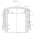
- the cap roughly comprises a top panel 1 and a skirt 2 hanging down from the peripheral edge of the top panel 1, and is provided, at the lower end of the skirt 2, with a tamper-evidence band (TE band) 5 via a bridge 3 that can be broken.
- TE band tamper-evidence band
- An inner ring 7 is formed on the inner surface of the top panel 1 so as to extend downward maintaining a distance from the skirt 2. It is desired to provide an outer ring 9 on the outer side of the inner ring 7, the outer ring 9 having a height lower than the inner ring 7.
- a screw thread 10 is formed on the inner surface of the skirt 2 so as to come into engagement with a screw thread 51 formed on the outer surface of the wall 50 of the mouth of the container. That is, the skirt 2 is turned (wrapped and tightened) in a closing direction and the screw thread 10 is brought into screw engagement with the screw thread 51 on the outer surface of the mouth-wall 50 of the container to mount the cap on the mouth-wall 50.
- the inner ring 7 has a shape which as a whole is inclined to expand outward as it goes downward and is forming an end portion of a decreased thickness. Therefore, when the cap is mounted on the mouth-wall 50 of the container and the upper portion of the mouth-wall 50 is fitted into space between the inner ring 7 and the skirt 2, the inner ring 7 easily deflects inward, and the outer surface of the inner ring 7 comes into intimate contact with the inner peripheral surface of the mouth-wall 50 to maintain good sealing.
- a seal point P is formed on the outer surface of the inner ring 7, and the outer surface of the inner ring 7 reliably comes into intimate contact with the inner peripheral surface of the mouth-wall 50 at the portion of the seal point P.
- the seal point P is an inflecting portion where the surface inclined outward as it goes downward is shifted to be inclined inward as it goes downward.
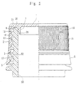
- the outer surface of the skirt 2 is knurled as designated at 11 for preventing the slipping, so that the cap can be smoothly turned in the closing direction and in the opening direction (see Fig. 2).
- Flap pieces 13 which have been known per se. are provided on the inner surfaces of the TE band 5 so as to come into engagement with a flange portion 52 of the mouth-wall 50 of the container. That is, when the cap that is wrapped and tightened on the mouth-wall 50 is opened, the flap pieces 13 come in contact with the flange portion 52, and the TE band 5 is limited from ascending.
- the skirt 2, on the other hand, rotates in the opening direction and ascends. Therefore, a bridge 3 linking the lower end of the skirt 2 to the TE band 5 is broken before the sealing portion (portion where the inner ring 7 is brought into intimate contact with the mouth-wall 50, or the seal point P that will be described later) is liberated, and the TE band 5 is removed from the cap.
- the TE band 5 that is removed from the cap proves the fact that the cap was once opened or the sealing portion was broken.
- slits 5 are formed in an upper part of the skirt 2 maintaining a suitable distance, enabling the gap between the cap and the mouth-wall 50 of the container to be washed.
- a recessed mark 17 for detection is provided at the peripheral edge of the top panel 1 for indicating the closed state of the cap, and a rib 19 is provided being corresponded to the mark 17 and is continuing from the inner surface of the top panel 1 to the upper end on the inner surface of the skirt 2. That is, a state where the cap is wrapped and tightened on the mouth-wall 50 can be confirmed in the step of production relying upon the position of the mark 17. Further, formation of the rib 19 permits the resin to smoothly flow at the time of forming the cap making it possible to avoid defective formation.
- the outer ring 9 is formed on the outer side of the inner ring 7 such that the inner surface thereof comes into intimate contact with the outer surface of the mouth-wall 50. That is, an intimate-contact point Q is formed on the inner surface of the outer ring 9, the intimate-contact point Q being an inflecting point where the surface inclined inward as it goes downward is shifted to be inclined outward as it goes downward, and the inner surface of the outer ring 9 comes into intimate contact with the outer surface of the mouth-wall 50 at the intimate-contact point Q.
- the outer ring 9 suppresses the play of when the cap is opened, and enhances the tamper evidence (TE).
- the inner ring 7 When, for example, the cap (skirt 2) is turned in the opening direction so as to be opened, the inner ring 7 can be turned in concentric with the inner peripheral surface of the mouth-wall 50 without play owing to the outer ring 9, and the angle of rotation can be widened until the seal is broken while stably maintaining the sealing relying upon the inner ring 7 and effectively avoiding the breakage of sealing before the bridge 3 is broken.
- the outer ring 9 is provided with a plurality of notches 23 for venting in the inner peripheral surface thereof that comes into intimate contact with the outer surface of at least the wall 50 of the mouth of the container. This function will be described later.
- an auxiliary protuberance 21 is formed on the inner surface of the top panel 1 at a portion between the outer ring 9 and the inner ring 7 and, particularly, at a portion close to the root of the outer ring 9.
- the auxiliary protuberance 21 comes into intimate contact with the corner portion of from the top surface of the mouth-wall 50 to the outer surface thereof, and reinforces the sealing which is accomplished by the inner ring 7. That is, a drop in the sealing can be effectively avoided by the provision of the auxiliary protuberance 21 in addition to the provision of the inner ring 7 even when there is formed fine ruggedness on the mouth-wall 50 due to the contraction at the time of forming the container.
- the small protuberance 25 has a function for preventing the over-tightening at the time of capping and for increasing the shock resistance. For example, shock that is exerted in the axial direction of the cap when it is dropped is relaxed by the small protuberance 25 that is in contact with the top surface of the mouth-wall 50, preventing the breakage of seal that is maintained by the intimate contact of the inner ring 7 with the inner surface of the mouth-wall 50, and by the intimate contact of the auxiliary protuberance 21 with the corner portion of the mouth-wall 50.
- shock that is exerted in the axial direction of the cap when it is dropped is relaxed by the small protuberance 25 that is in contact with the top surface of the mouth-wall 50, preventing the breakage of seal that is maintained by the intimate contact of the inner ring 7 with the inner surface of the mouth-wall 50, and by the intimate contact of the auxiliary protuberance 21 with the corner portion of the mouth-wall 50.
- the small protuberance 25 is in contact with the top surface of the mouth-wall 50 in a state where the cap is being mounted on the mouth-wall 50.
- the small protuberance 25, however, may be separated away from the top surface of the mouth-wall 50. That is, the shock can be relaxed and the breakage of seal is prevented even when the small protuberance 25 is brought into contact with the top surface of the mouth-wall 50 upon the application of an external force.
- the small protuberance 25 may be circularly formed or may be intermittently formed. In particular, the sealing can be enhanced by circularly forming the small protuberance 25 and by causing an end thereof to come into intimate contact with the top surface of the mouth-wall 50.
- a slender recessed portion 30 is formed in the inner surface of the inner ring 7 so as to extend upward from an end thereof. That is, referring to Fig. 4 as well as Figs. 5 and 6 illustrating a state where a doming is taking place due to an increase in the pressure in the container, when the top panel 1 of the cap swells outward, the inner ring 7 is easily so deformed (i.e., so inclined) that an end thereof is directed to the inside.
- the portion having the recessed portion 30 formed therein tends to be easily deformed, and deformation of the inner ring 7 is promoted starting from the above portion.
- the outer surface (particularly, seal point P) of the inner rang 7 separates away from the inner surface of the mouth-wall 50 and, at the same time, a gap is formed between the mouth-wall 50 and the protuberance 25 or the auxiliary protuberance 21 that is formed near the root of the outer ring 9.
- notches 23 have been formed in the outer ring 9. According to the present invention, therefore, the gas is smoothly vented when the doming takes place to a large degree due to an increase in the pressure in the container in excess of a predetermined value, effectively preventing the popping up of the cap or the breakage of the container caused by a large increase in the pressure in the container.
- the notches 23 are formed in a plural number (e.g., three).
- At least one notch 23 is desirably located near the recessed portion 30. Further, the notch 23 has a width of about 3 mm in the circumferential direction and a depth (at the intimate-contact point Q) of about 0.1 mm.
- the greatest advantage of the present invention is that as a result of forming the recessed portion 30 in the inner surface of the inner ring 7, the inner ring 7 can be easily deformed when the doming occurs despite the inner ring 7 possesses a thickness which is large enough to maintain good sealing. That is, the inner ring 7 accomplishes excellent sealing as well as excellent venting.
- the recessed portion 30 formed in the inner surface of the inner ring 7 extends upward to be higher than the seal point P formed on the outer surface of the inner ring 7. That is, if the height H of the upper end of the recessed portion 30 is lower than the seal point P, the seal point P is not sufficiently separated away from the inner surface of the mouth-wall 50, which results in a decrease in the venting.
- the recessed portion 30 is extending on the way of the inner ring 7 from the end of the inner ring 7. As shown in Fig. 7 which is a view of a major portion on an enlarged scale, however, the recessed portion 30 can be formed, for example, all the way from the end to the root of the inner ring 7. In this case, the inner ring 7 can be deformed to a maximum degree when the doming takes place, and a maximum degree of venting is accomplished.
- the inner ring 7 tends to be highly deformed causing a decrease in the tamper evidence. That is, when the inner ring 7 is easily deformed, the seal is subject to be broken with a small angle of rotation when the cap is turned and is removed from the mouth-wall 50; i.e., the seal is broken before the above bridge 3 is broken.
- the breakage of seal that takes place before the bridge 3 is broken means that the seal breaks even when the TE band 5 has not been separated away or, in other words, means a decrease in the tamper evidence.
- the upper end position of the recessed portion 30 it is desired to so determine the upper end position of the recessed portion 30 as to exhibit excellent venting without spoiling the tamper evidence.
- the upper end position H of the recessed portion 30 is higher than the seal point P and, particularly, the upper end position H of the recessed portion 30 is over the seal point P of the inner ring 7 by 0.1 to 1.8 mm.
- the venting tends to decrease.
- the upper end position H of the recessed portion 30 is higher than the above range, on the other hand, the tamper evidence tends to be deteriorated.
- the recessed portion 30 may be formed in a number of one or in a plural number.
- the recessed portions 30 are formed in a plural number (six).
- increasing the number of the recessed portions 30 may cause the inner ring 7 to be deformed unnecessarily resulting in a decrease in the sealing or in the tamper evidence.
- the recessed portions 30 are formed in a plural number as shown in Fig. 8, the plurality of recessed portions may be symmetrically formed maintaining a predetermined distance or may be formed being collected in part of the regions of the inner surface of the inner ring 7 in the circumferential direction thereof. With the plurality of recessed portions 30 being formed in a collected manner in particular, the inner ring 7 is deformed in a distorted manner when the internal pressure is elevated, causing the intimate contact to be easily broken due to the deformation and enhancing the venting.
- a maximum thickness t (see Fig. 4) of the inner ring 7 in the horizontal direction is in a range of 0.5 to 1.5 mm in a portion where the recessed portion 30 is formed, and the width w (see Fig. 3) of the recessed portion 30 is in a range of 0.5 to 6 mm.
- the inner ring 7 tends to be easily deformed causing a decrease in the sealing or in the tamper evidence.
- the depth of the recessed portion 30 is, usually, in a range of 0.05 to 0.30 mm.
- notch 23 for venting is formed by cutting the inner surface only of the outer ring 9. As shown in Fig. 9, however, it is also allowable to form the notch 23 for venting by cutting off the whole lower portion of the outer ring 9 but including an intimate-contact point Q.
- the seal is effectively avoided from being broken by the play of the cap at the time when the cap is opened, the seal is not broken before the bridge 3 is broken, and tamper evidence is favorably maintained.
- the venting is enhanced when the doming takes place.
- the cap of the invention can be produced by using various plastic materials such as a low-, intermediate- or high-density polyethylene, a linear low-density polyethylene, a polypropylene, a thermoplastic polyester, a polyamide, a styrene resin or an ABS resin relying upon the integral molding such as injection molding or compression molding.
- plastic materials such as a low-, intermediate- or high-density polyethylene, a linear low-density polyethylene, a polypropylene, a thermoplastic polyester, a polyamide, a styrene resin or an ABS resin relying upon the integral molding such as injection molding or compression molding.
- One recessed portion 30 (width w of 3 mm) was formed.
- the distance between the upper end position H of the recessed portion 30 and the seal point P was 0.4 mm.
- the root portion of the inner ring 7 forming the recessed portion 30 therein possessed a thickness of 1.1 mm, and the recessed portion 30 possessed a depth of 0.1 mm.
- a cap B was formed in quite the same manner as the cap A but forming six recessed portions 30 in the inner surface of the inner ring 7 maintaining an equal distance, each recessed portion 30 having a width w of 1 mm, a depth of 0.15 mm and running over the full length from the end of the inner ring 7 up to the root portion thereof.
- a cap C was formed in quite the same manner as the cap A but without forming recessed portion 30 in the inner surface of the inner ring 7.
- 500-Milliliter PET bottles were filled with a 1% orthotolidine aqueous solution heated at 87°C, wrap-tightened with caps A to C, cooled with the shower, and preserved at normal temperature for 24 hours to prepare test samples on which the caps A to C were wrap-tightened, each in a number of 10.
- Hypochlorous acid was dropped on the caps of the test samples each of a number of 10 prepared above.
- the test samples in an inverted state were dropped in a vertical direction on a steel cylindrical member of which the upper surface had been inclined at 10° from a height of 100 cm. Thereafter, the test samples were immersed in the hypochlorous acid diluted with the tap water of 5°C for 24 hours.
- 500-Milliliter PET bottles were filled with the tap water heated at 87°C, wrap-tightened with caps A to C, cooled with the shower, and preserved at normal temperature for 24 hours to prepare test samples on which the caps A to C were wrap-tightened, each in a number of 10.
- test samples each of a number of 10 prepared above were held in a water vessel, and a needle having a nitrogen injection hole was stubbed into the top panels of the caps. Nitrogen was injected through the injection hole at a rate of 0.034 MPa/sec to measure the pressure in the bottle at which the seal between the bottle and the cap was broken and nitrogen leaked out. Here, however, the measurement was taken in a state where the test samples were held in a casing such that the bottles were not broken by the pressure of the gas.
- 500-Milliliter PET bottles were filled with the water heated at 87°C, wrap-tightened with caps A to C, cooled with the shower, and preserved at normal temperature for 24 hours to prepare test samples on which the caps A to C were wrap-tightened, each in a number of 10.
- test samples were measured for their leak angles and bridge angles by the methods described below.
- a straight line was drawn on the caps and on the bottles by using a black Magic Ink (i.e., marked with a marking ink).
- the cap was turned in the opening direction at a predetermined low speed to calculate an angle of rotation (leak angle) of the cap of when the level of water started moving in the bottle and an angle of rotation (bridge angle) of the cap of when the bridge coupling the TE band started breaking from a deviation between the straight line drawn on the bottle and the straight line drawn on the cap.
- the leak angle represents the angle of rotation of the cap until the seal is broken in opening the cap, and the start of motion of the level of water in the bottle is judged by naked eyes. In calculating the bridge angle, further, the breakage of the bridge was judged relying upon the sound that generated when the bridge was broken.
- BL angle ( leak angle ) - ( bridge angle ) for all of the samples, and the number of the samples having BL angles of a minus sign were found.
- the BL angle of the minus sign means that the sealing is breaking before the bridge is broken.
- the larger the number of samples having BL angles of the minus sign the lower the tamper evidence.
- the smaller the number of samples having BL angles of the minus sign on the other hand, the more excellent the tamper evidence.
- the BL angles of the minus sign were exhibited by none of the test samples wrap-tightened with the caps A and C each of the numbers of 10. Among 10 testing samples wrap-tightened with the caps B, however, two of them exhibited BL angles of the minus sign.
Landscapes
- Engineering & Computer Science (AREA)
- Mechanical Engineering (AREA)
- Closures For Containers (AREA)
Applications Claiming Priority (1)
| Application Number | Priority Date | Filing Date | Title |
|---|---|---|---|
| JP2004364348 | 2004-12-16 |
Publications (3)
| Publication Number | Publication Date |
|---|---|
| EP1679267A2 true EP1679267A2 (de) | 2006-07-12 |
| EP1679267A3 EP1679267A3 (de) | 2006-07-19 |
| EP1679267B1 EP1679267B1 (de) | 2011-03-30 |
Family
ID=36046903
Family Applications (1)
| Application Number | Title | Priority Date | Filing Date |
|---|---|---|---|
| EP05112068A Ceased EP1679267B1 (de) | 2004-12-16 | 2005-12-13 | Plastikverschluss mit hervorragenden Dichtungs- und Entlüftungseigenschaften |
Country Status (5)
| Country | Link |
|---|---|
| US (1) | US7575121B2 (de) |
| EP (1) | EP1679267B1 (de) |
| KR (1) | KR101186074B1 (de) |
| CN (1) | CN1799946B (de) |
| DE (1) | DE602005027170D1 (de) |
Cited By (8)
| Publication number | Priority date | Publication date | Assignee | Title |
|---|---|---|---|---|
| USD633386S1 (en) | 2010-05-27 | 2011-03-01 | Silgan White Cap LLC | Closure |
| USD634200S1 (en) | 2010-05-27 | 2011-03-15 | Silgan White Cap LLC | Closure |
| USD634199S1 (en) | 2010-05-27 | 2011-03-15 | Silgan White Cap LLC | Closure |
| US8231020B2 (en) | 2010-05-27 | 2012-07-31 | Silgan White Cap LLC | Impact resistant closure |
| WO2015067598A2 (en) | 2013-11-08 | 2015-05-14 | L'oreal | Assembly for packaging a cosmetic product |
| WO2019094339A1 (en) * | 2017-11-07 | 2019-05-16 | Closure Systems International Inc. | Closure and package that vents at high pressure |
| WO2020007832A1 (de) * | 2018-07-05 | 2020-01-09 | Bericap Gmbh & Co. Kg | Schraubverschluss mit kontrollierter dichtung |
| RU2773542C1 (ru) * | 2018-07-05 | 2022-06-06 | Берикап Гмбх Унд Ко. Кг | Навинчивающаяся крышка с контролируемым уплотнением |
Families Citing this family (40)
| Publication number | Priority date | Publication date | Assignee | Title |
|---|---|---|---|---|
| GB2417240B (en) * | 2004-08-20 | 2007-09-26 | Beeson & Sons Ltd | Container closure assembly with internal neck thread |
| CN101142126A (zh) * | 2005-03-14 | 2008-03-12 | 克雷诺瓦通用密封有限公司 | 瓶盖 |
| DE102006047023B4 (de) * | 2006-10-02 | 2010-02-25 | Fabian Schellenbach | Verschluss |
| US20080110851A1 (en) * | 2006-10-13 | 2008-05-15 | Owens-Illinois Closure Inc. | Dual seal closure and package |
| CA2577886C (fr) * | 2007-02-13 | 2015-09-08 | Crealise Conditionnement Inc. | Bouchon sans joint rapporte |
| US8047398B2 (en) * | 2007-06-22 | 2011-11-01 | Kraft Foods Global Brands Llc | Snap overcap closure for a container |
| US20090107997A1 (en) * | 2007-10-30 | 2009-04-30 | Cornelius Derek W | Leak-proof drinking cup and lid assembly |
| JP5398547B2 (ja) * | 2007-12-28 | 2014-01-29 | 日本山村硝子株式会社 | 合成樹脂製キャップ |
| US8240492B2 (en) * | 2008-04-23 | 2012-08-14 | RFR Design LLC | Snap closure |
| US9598200B2 (en) * | 2009-11-17 | 2017-03-21 | Jeong-min Lee | Connection die coupled with container neck in use |
| DE102009044896B3 (de) * | 2009-12-15 | 2011-05-26 | Kunststofftechnik Waidhofen An Der Thaya Gmbh | Verschlusskappe zum Verschließen eines Behältnisses |
| EP2521673A4 (de) * | 2010-01-06 | 2013-05-22 | Daniel P Soehnlen | Kombinierte lippen- und ansatzdichtung für drehdeckel |
| FR2956387B1 (fr) * | 2010-02-15 | 2012-07-06 | Tetra Laval Holdings & Finance | Bouchon pour un col de recipient |
| JP5464519B2 (ja) * | 2010-02-26 | 2014-04-09 | 株式会社吉野工業所 | ネジキャップ付き容器 |
| AU2011204806A1 (en) * | 2010-07-23 | 2012-02-09 | Christopher Campbell Win | Tamper Evident closure |
| US8763830B2 (en) * | 2010-10-15 | 2014-07-01 | Closure Systems International Inc. | Tamper-evident closure having tamper-indicating pilfer band with projections and package including the tamper-evident closure |
| IT1403118B1 (it) * | 2010-12-09 | 2013-10-04 | Supercap S R L | Struttura di collo di bottiglia e relativo tappo in materiali plastici, particolarmente per acque e bibite. |
| ES2535320T3 (es) * | 2010-12-23 | 2015-05-08 | Obrist Closures Switzerland Gmbh | Cierre para un envase |
| ES2550510T3 (es) | 2011-01-14 | 2015-11-10 | Creanova Universal Closures Limited | Cierre |
| JP5898948B2 (ja) * | 2011-12-27 | 2016-04-06 | 株式会社Csiジャパン | 合成樹脂製キャップ、閉止装置、および飲料入り閉止装置 |
| US10472134B1 (en) | 2013-01-07 | 2019-11-12 | Celebrate Everywhere, LLC | Container cap securing and venting |
| US9428292B2 (en) | 2013-03-13 | 2016-08-30 | Silgan White Cap LLC | Fluid injection system and method for supporting container walls |
| PE20170005A1 (es) | 2014-02-14 | 2017-03-04 | Closure Systems Int Inc | Cierre a prueba de manipulaciones mejorado |
| CA3040246A1 (en) * | 2015-10-16 | 2017-04-20 | Zipz, Inc. | Carbonated beverage closure |
| CN105857816A (zh) * | 2016-06-22 | 2016-08-17 | 苏州宝柏塑胶有限公司 | 一种密封透气容器结构 |
| US10532858B2 (en) | 2017-09-06 | 2020-01-14 | Creanova Universal Closures Ltd. | Closure for container neck finishes |
| US11060653B2 (en) * | 2018-08-09 | 2021-07-13 | Hanon Systems | Gap filling shipping cap for leveraged refrigerant fitting |
| JP7347938B2 (ja) * | 2019-02-27 | 2023-09-20 | 日本クロージャー株式会社 | 樹脂製容器口部とプラスチックキャップとの組み合わせ |
| EP4464619A3 (de) * | 2019-07-16 | 2025-01-01 | Jin Hee Ahn | Behälterkappe und damit kombinierter behälter |
| MX2022003309A (es) | 2019-10-07 | 2022-04-12 | Closure Systems Int Inc | Tapa abatible. |
| US11591141B2 (en) * | 2020-07-08 | 2023-02-28 | Veraseal Pty Limited | Closures and vessels with closures |
| US11325752B2 (en) | 2020-09-02 | 2022-05-10 | United Semiconductor Japan Co., Ltd. | Bottle cap and bottle |
| USD1063612S1 (en) | 2020-09-28 | 2025-02-25 | Closure Systems International Inc. | Closure with tamper-evident band |
| USD1063613S1 (en) | 2020-09-28 | 2025-02-25 | Closure Systems International Inc. | Closure with tamper-evident band |
| CN112744448A (zh) * | 2021-01-13 | 2021-05-04 | 东莞穗联包装制品有限公司 | 一种防爆盖及瓶 |
| USD996968S1 (en) | 2021-05-17 | 2023-08-29 | Closure Systems International Inc. | Closure |
| USD996967S1 (en) | 2021-05-17 | 2023-08-29 | Closure Systems International Inc. | Closure |
| US12600529B2 (en) * | 2022-06-10 | 2026-04-14 | Reliance Bp Mobility Limited | Pilferproof cap assembly for a container |
| EP4714855A2 (de) | 2023-04-05 | 2026-03-25 | Husky Injection Molding Systems Ltd. | Verschlüsse mit manipulationsnachweis |
| USD1116829S1 (en) * | 2023-06-13 | 2026-03-10 | Husky Injection Molding Systems Ltd. | Bottle cap |
Family Cites Families (38)
| Publication number | Priority date | Publication date | Assignee | Title |
|---|---|---|---|---|
| US3055526A (en) * | 1959-12-21 | 1962-09-25 | Robert L Plunkett | Plastic cap |
| NL300885A (de) * | 1962-11-23 | |||
| DE1432178A1 (de) * | 1963-11-07 | 1968-12-19 | Walter Heubl | Flaschenverschluss aus Kunststoff |
| US3411649A (en) * | 1966-09-19 | 1968-11-19 | Owens Illinois Inc | Closure for reducing heat transfer to product during processing |
| US3441161A (en) * | 1967-03-09 | 1969-04-29 | Paul S Van Baarn | Bottle cap |
| US3494496A (en) * | 1968-01-08 | 1970-02-10 | Jay G Livingstone | Closure cap and container-and-cap assembly |
| US3568871A (en) * | 1969-05-12 | 1971-03-09 | Jay G Livingstone | Closure cap |
| US3707240A (en) * | 1970-08-27 | 1972-12-26 | Polytop Corp | Closure with tear-off skirt |
| US3901404A (en) * | 1972-05-18 | 1975-08-26 | Dairy Cap Corp | Bottle cap |
| US3815771A (en) * | 1972-06-07 | 1974-06-11 | Anchor Cap & Closure Corp | Linerless closure cap |
| US3844439A (en) * | 1972-07-28 | 1974-10-29 | Consumers Glass Co Ltd | Linerless closures |
| CH607702A5 (en) * | 1975-08-18 | 1978-10-13 | Obrist Ag Albert | Bottle closure, in particular a screw closure, and process for fastening the closure |
| US3991895A (en) * | 1976-02-20 | 1976-11-16 | Theodore Wayne Thornton | Moisture-proof container seal |
| US4165009A (en) * | 1978-01-12 | 1979-08-21 | Japan Crown Cork Co., Ltd. | Bottle closure for sales promotion |
| US4322012A (en) * | 1980-05-09 | 1982-03-30 | Dairy Cap Corporation | Threaded plastic bottle cap |
| US4331249A (en) * | 1981-03-10 | 1982-05-25 | The Continental Group, Inc. | Plastic closure member with flowed-in liner |
| EP0093690A1 (de) * | 1982-05-04 | 1983-11-09 | Crown Obrist AG | Verschlusskappe für Behälter |
| US4442947A (en) * | 1983-01-18 | 1984-04-17 | Continental White Cap, Inc. | Plastic closure with sealing flaps |
| US4560077A (en) * | 1984-09-25 | 1985-12-24 | Sun Coast Plastics, Inc. | Plastic closure cap |
| US5348183A (en) * | 1991-03-05 | 1994-09-20 | Portola Packaging, Inc. | Tamper-evident, initially unitary, fitment and closure |
| US5275287A (en) * | 1991-04-10 | 1994-01-04 | Mcg Closures Ltd. | Closures |
| DE4221004A1 (de) * | 1992-06-26 | 1994-01-05 | Mouldtec Pvg Ag Meilen | Verschlußkappe für Getränkeflaschen |
| JPH06122462A (ja) * | 1992-10-06 | 1994-05-06 | Dainippon Printing Co Ltd | 密閉キャップ |
| ES2119132T3 (es) * | 1993-12-23 | 1998-10-01 | Crown Cork Ag | Caperuza de cierre de material sintetico con junta interior con ventilacion precoz. |
| DE29623290U1 (de) * | 1995-10-31 | 1998-02-19 | Safety Cap System AG, Steinhausen | Verschluß für eine Flasche o.dgl. |
| CN1080688C (zh) * | 1996-03-12 | 2002-03-13 | 李贞旻 | 合成树脂瓶盖 |
| JP3872546B2 (ja) | 1996-07-29 | 2007-01-24 | 日本クラウンコルク株式会社 | ワンピース型プラスチックキャップ |
| DE19705717A1 (de) * | 1997-02-14 | 1998-08-20 | Bericap Gmbh & Co Kg | Kunststoffschraubverschluß |
| EP0982234A1 (de) * | 1998-08-22 | 2000-03-01 | Crown Cork & Seal Technologies Corporation | Verschlusskappe |
| AUPP935299A0 (en) * | 1999-03-19 | 1999-04-15 | Closures And Packaging Services Limited | Container closure |
| DE19952214B4 (de) * | 1999-10-29 | 2005-02-10 | Henzi-Breuer, Bianca | Becherförmiger Schraubverschluss |
| KR20010096600A (ko) * | 2000-03-13 | 2001-11-07 | 도케 케이시 | 합성수지제 용기뚜껑 |
| US6491175B1 (en) * | 2000-06-28 | 2002-12-10 | Saad Taha | Single piece closure for a pressurized container |
| JP2003175948A (ja) * | 2001-12-11 | 2003-06-24 | Alcoa Closure Systems Japan Ltd | 合成樹脂製キャップ |
| JP2003261155A (ja) * | 2002-03-04 | 2003-09-16 | Alcoa Closure Systems Japan Ltd | 合成樹脂製キャップ |
| DE20210304U1 (de) * | 2002-07-03 | 2002-08-29 | Plamatec AG, Fällanden | Verschlusskappe |
| JP2004224371A (ja) * | 2003-01-21 | 2004-08-12 | Alcoa Closure Systems Japan Ltd | 合成樹脂製キャップ、閉止装置、および容器詰め飲料 |
| US20060151423A1 (en) * | 2004-03-11 | 2006-07-13 | Seidita Thomas M | Closure having tapered sealing plug |
-
2005
- 2005-12-13 EP EP05112068A patent/EP1679267B1/de not_active Ceased
- 2005-12-13 DE DE602005027170T patent/DE602005027170D1/de not_active Expired - Lifetime
- 2005-12-15 US US11/300,401 patent/US7575121B2/en active Active
- 2005-12-15 KR KR1020050123744A patent/KR101186074B1/ko not_active Expired - Lifetime
- 2005-12-16 CN CN2005101047523A patent/CN1799946B/zh not_active Expired - Fee Related
Cited By (10)
| Publication number | Priority date | Publication date | Assignee | Title |
|---|---|---|---|---|
| USD633386S1 (en) | 2010-05-27 | 2011-03-01 | Silgan White Cap LLC | Closure |
| USD634200S1 (en) | 2010-05-27 | 2011-03-15 | Silgan White Cap LLC | Closure |
| USD634199S1 (en) | 2010-05-27 | 2011-03-15 | Silgan White Cap LLC | Closure |
| US8231020B2 (en) | 2010-05-27 | 2012-07-31 | Silgan White Cap LLC | Impact resistant closure |
| US8672158B2 (en) | 2010-05-27 | 2014-03-18 | Silgan White Cap LLC | Impact resistant closure |
| WO2015067598A2 (en) | 2013-11-08 | 2015-05-14 | L'oreal | Assembly for packaging a cosmetic product |
| WO2019094339A1 (en) * | 2017-11-07 | 2019-05-16 | Closure Systems International Inc. | Closure and package that vents at high pressure |
| US10407225B2 (en) | 2017-11-07 | 2019-09-10 | Closure Systems International Inc. | Closure and package that vents at high pressure |
| WO2020007832A1 (de) * | 2018-07-05 | 2020-01-09 | Bericap Gmbh & Co. Kg | Schraubverschluss mit kontrollierter dichtung |
| RU2773542C1 (ru) * | 2018-07-05 | 2022-06-06 | Берикап Гмбх Унд Ко. Кг | Навинчивающаяся крышка с контролируемым уплотнением |
Also Published As
| Publication number | Publication date |
|---|---|
| US20060138073A1 (en) | 2006-06-29 |
| KR20060069288A (ko) | 2006-06-21 |
| EP1679267A3 (de) | 2006-07-19 |
| DE602005027170D1 (de) | 2011-05-12 |
| KR101186074B1 (ko) | 2012-09-25 |
| CN1799946B (zh) | 2010-08-18 |
| CN1799946A (zh) | 2006-07-12 |
| US7575121B2 (en) | 2009-08-18 |
| EP1679267B1 (de) | 2011-03-30 |
Similar Documents
| Publication | Publication Date | Title |
|---|---|---|
| US7575121B2 (en) | Plastic cap featuring excellent sealing and venting | |
| US5452818A (en) | Reusable beverage can closure | |
| US10899505B2 (en) | Band-receiving closure with recess | |
| RU2114036C1 (ru) | Пластмассовая крышка для сосуда | |
| JP5977937B2 (ja) | 炭酸飲料充てん容器用合成樹脂製キャップ、閉止装置、および飲料入り閉止装置 | |
| US20020158037A1 (en) | Plastic container closure | |
| US20190337691A1 (en) | Venting Closure | |
| US3292807A (en) | Tamper-proof closure | |
| US4623070A (en) | Closure cap | |
| JP4810202B2 (ja) | シール性とガス抜き性に優れたプラスチックキャップ | |
| US6726043B2 (en) | Container and plastic threadless closure member | |
| US8096433B2 (en) | Hermetically sealed container | |
| ES2553173B1 (es) | Combinación de envase y cierre de metal | |
| JP2004352261A (ja) | 耐内圧性とラベル貼付性とに優れたプラスチックキャップ | |
| JP2013082463A (ja) | 容器蓋 | |
| JP5201844B2 (ja) | キャップ | |
| JP4714332B2 (ja) | 合成樹脂製キャップ | |
| CN214876895U (zh) | 瓶盖和包装瓶 | |
| JP2005289499A (ja) | 容器の封鎖構造 | |
| JP4379859B2 (ja) | キャップ | |
| KR200239531Y1 (ko) | 포장용기 뚜껑 | |
| JP2006273374A (ja) | ネジ付き缶用キャップの密封ライナー構造 | |
| JPH0912054A (ja) | 不正開封防止用ヒンジ付キャップ | |
| JP2007238100A (ja) | ガス含有飲料の容器及びその充填方法 | |
| GB2348193A (en) | Cap with an inwardly curving inner skirt |
Legal Events
| Date | Code | Title | Description |
|---|---|---|---|
| PUAI | Public reference made under article 153(3) epc to a published international application that has entered the european phase |
Free format text: ORIGINAL CODE: 0009012 |
|
| PUAL | Search report despatched |
Free format text: ORIGINAL CODE: 0009013 |
|
| AK | Designated contracting states |
Kind code of ref document: A2 Designated state(s): AT BE BG CH CY CZ DE DK EE ES FI FR GB GR HU IE IS IT LI LT LU LV MC NL PL PT RO SE SI SK TR |
|
| AX | Request for extension of the european patent |
Extension state: AL BA HR MK YU |
|
| AK | Designated contracting states |
Kind code of ref document: A3 Designated state(s): AT BE BG CH CY CZ DE DK EE ES FI FR GB GR HU IE IS IT LI LT LU LV MC NL PL PT RO SE SI SK TR |
|
| AX | Request for extension of the european patent |
Extension state: AL BA HR MK YU |
|
| AKX | Designation fees paid | ||
| 17P | Request for examination filed |
Effective date: 20061219 |
|
| RBV | Designated contracting states (corrected) |
Designated state(s): DE GB |
|
| 17Q | First examination report despatched |
Effective date: 20070321 |
|
| REG | Reference to a national code |
Ref country code: DE Ref legal event code: 8566 |
|
| GRAP | Despatch of communication of intention to grant a patent |
Free format text: ORIGINAL CODE: EPIDOSNIGR1 |
|
| GRAS | Grant fee paid |
Free format text: ORIGINAL CODE: EPIDOSNIGR3 |
|
| GRAA | (expected) grant |
Free format text: ORIGINAL CODE: 0009210 |
|
| AK | Designated contracting states |
Kind code of ref document: B1 Designated state(s): DE GB |
|
| REG | Reference to a national code |
Ref country code: GB Ref legal event code: FG4D |
|
| REF | Corresponds to: |
Ref document number: 602005027170 Country of ref document: DE Date of ref document: 20110512 Kind code of ref document: P |
|
| REG | Reference to a national code |
Ref country code: DE Ref legal event code: R096 Ref document number: 602005027170 Country of ref document: DE Effective date: 20110512 |
|
| PLBE | No opposition filed within time limit |
Free format text: ORIGINAL CODE: 0009261 |
|
| STAA | Information on the status of an ep patent application or granted ep patent |
Free format text: STATUS: NO OPPOSITION FILED WITHIN TIME LIMIT |
|
| 26N | No opposition filed |
Effective date: 20120102 |
|
| REG | Reference to a national code |
Ref country code: DE Ref legal event code: R097 Ref document number: 602005027170 Country of ref document: DE Effective date: 20120102 |
|
| REG | Reference to a national code |
Ref country code: DE Ref legal event code: R082 Ref document number: 602005027170 Country of ref document: DE Representative=s name: HOEGER, STELLRECHT & PARTNER PATENTANWAELTE MB, DE |
|
| PGFP | Annual fee paid to national office [announced via postgrant information from national office to epo] |
Ref country code: GB Payment date: 20221027 Year of fee payment: 18 Ref country code: DE Payment date: 20221102 Year of fee payment: 18 |
|
| REG | Reference to a national code |
Ref country code: DE Ref legal event code: R119 Ref document number: 602005027170 Country of ref document: DE |
|
| GBPC | Gb: european patent ceased through non-payment of renewal fee |
Effective date: 20231213 |
|
| PG25 | Lapsed in a contracting state [announced via postgrant information from national office to epo] |
Ref country code: DE Free format text: LAPSE BECAUSE OF NON-PAYMENT OF DUE FEES Effective date: 20240702 |
|
| PG25 | Lapsed in a contracting state [announced via postgrant information from national office to epo] |
Ref country code: GB Free format text: LAPSE BECAUSE OF NON-PAYMENT OF DUE FEES Effective date: 20231213 |
|
| PG25 | Lapsed in a contracting state [announced via postgrant information from national office to epo] |
Ref country code: GB Free format text: LAPSE BECAUSE OF NON-PAYMENT OF DUE FEES Effective date: 20231213 Ref country code: DE Free format text: LAPSE BECAUSE OF NON-PAYMENT OF DUE FEES Effective date: 20240702 |