EP1679283A1 - Treibscheibenschutz - Google Patents
Treibscheibenschutz Download PDFInfo
- Publication number
- EP1679283A1 EP1679283A1 EP05112074A EP05112074A EP1679283A1 EP 1679283 A1 EP1679283 A1 EP 1679283A1 EP 05112074 A EP05112074 A EP 05112074A EP 05112074 A EP05112074 A EP 05112074A EP 1679283 A1 EP1679283 A1 EP 1679283A1
- Authority
- EP
- European Patent Office
- Prior art keywords
- protective
- claw
- receptacle
- sliding element
- traction sheave
- Prior art date
- Legal status (The legal status is an assumption and is not a legal conclusion. Google has not performed a legal analysis and makes no representation as to the accuracy of the status listed.)
- Granted
Links
- 230000004224 protection Effects 0.000 title claims description 17
- 230000001681 protective effect Effects 0.000 claims abstract description 106
- 210000000078 claw Anatomy 0.000 claims description 57
- 238000006073 displacement reaction Methods 0.000 description 7
- 229910000831 Steel Inorganic materials 0.000 description 5
- 239000010959 steel Substances 0.000 description 5
- 208000027418 Wounds and injury Diseases 0.000 description 2
- 230000006978 adaptation Effects 0.000 description 2
- 230000006378 damage Effects 0.000 description 2
- 208000014674 injury Diseases 0.000 description 2
- 238000005452 bending Methods 0.000 description 1
- 238000009434 installation Methods 0.000 description 1
- 230000001012 protector Effects 0.000 description 1
Images


Classifications
-
- B—PERFORMING OPERATIONS; TRANSPORTING
- B66—HOISTING; LIFTING; HAULING
- B66D—CAPSTANS; WINCHES; TACKLES, e.g. PULLEY BLOCKS; HOISTS
- B66D1/00—Rope, cable, or chain winding mechanisms; Capstans
- B66D1/54—Safety gear
-
- B—PERFORMING OPERATIONS; TRANSPORTING
- B66—HOISTING; LIFTING; HAULING
- B66B—ELEVATORS; ESCALATORS OR MOVING WALKWAYS
- B66B11/00—Main component parts of lifts in, or associated with, buildings or other structures
- B66B11/04—Driving gear ; Details thereof, e.g. seals
-
- B—PERFORMING OPERATIONS; TRANSPORTING
- B66—HOISTING; LIFTING; HAULING
- B66B—ELEVATORS; ESCALATORS OR MOVING WALKWAYS
- B66B5/00—Applications of checking, fault-correcting, or safety devices in elevators
- B66B5/0043—Devices enhancing safety during maintenance
- B66B5/005—Safety of maintenance personnel
Definitions
- the invention relates to a protective device for the inlet or outlet region of a traction mechanism on a traction sheave or deflection roller of a traction mechanism drive mounted on a carrier, with a protective claw, wherein the protective claw is mounted on a holding device.
- the object of the invention is to design and arrange a protective device in such a way that it can be mounted on various models of traction mechanism drives and increases safety.
- the holding device at least one displaceable and / or displaceably arranged on the carrier base plate, at least one displaceable on the base plate and / or slidably arranged receptacle and at least one offset and / or slidably arranged on the receptacle Sliding element, wherein the protective claw is arranged pivotally and / or displaceable medium and / or directly on the sliding element.
- the protection device can be adapted not only in advance in certain areas flexibly to the conditions of the respective traction drive, but also be adapted manually on site mounting.
- the individual members of the holding device can be made independently of the traction drive and independently and each have a simple and conventional in their basic form.
- the base plate is displaceable and / or displaceably mounted and fixable at least in the direction of a longitudinal axis of the carrier. This ensures that the protective device is universally applicable to almost all types of traction drives, as almost all traction drives are mounted on supports. A special adaptation of the holding device to the structure of Switzerlandstoffantriebs deleted.
- the base plate and / or the receptacle have at least one slot and / or a bore for at least a first retaining bolt, via which the receptacle is attachable to the base plate, and the receptacle relative to the base plate continuously or in Stages adjustable and fixable.
- the base plate is usually aligned parallel to the axis of rotation of the traction sheave, so that the recording can be moved and fixed by the slot in relation to the traction sheave. This is in addition to the base plate also the inclusion as a second member of the holding device adjustable.
- the receptacle and / or the sliding element have at least one elongated hole and / or a bore for at least one second retaining bolt, via which the sliding element can be fastened to the receptacle, and the sliding element relative to the recording continuously or in stages adjustable and can be fixed.
- the adjustability of the third member of the holding device is ensured.
- the three members can thus be moved and fixed in all three orthogonal spatial directions.
- the receptacle is displaceable in a direction perpendicular to the longitudinal axis of the carrier and the sliding element in a direction perpendicular to the direction of displacement of the receptacle.
- the protective claw from the carrier or the foundation can be adapted to any traction drive.
- the sliding element and / or the protective claw have at least one elongated hole for a third retaining pin and / or at least one bore for a pivot pin, via which the protective claw on the sliding element can be fastened, and the protective claw relative to the sliding element pivotally adjustable and can be fixed.
- the actual, forming the protection fourth member, namely the protective claw be adapted to the course of the traction means.
- the pivot pin forms a pivot axis.
- the protective claw In the circumferential direction about the pivot axis, the protective claw can be through the retaining bolts set, which is guided in a part-circular slot.
- a fourth degree of freedom is created by the possibility of pivoting, which ensures the universal adjustability to many different traction mechanism drives.
- the protective claw is formed at least in two parts, has a U-shaped cross-sectional profile with two flanks and with a width and the U-shaped cross-sectional profile is adjustable in width.
- Traction drives differ in the diameter of the traction sheaves and in the number of traction means, which are guided side by side on a traction sheave. As the number of traction means increases, the traction sheaves become wider.
- the substantially U-shaped protective claw encloses the traction sheave and the traction means, wherein the two flanks are each arranged outside the traction sheave directly next to the traction sheave. Due to the adjustability of the width of the protective claw, this can be adapted to different wide traction sheaves. The closer the protective claw to the traction sheave and the traction means, the more secure the protective device, so that the adjustability of the width increases the safety of the protective device.
- the position of the protective claw with respect to a rotational axis of the traction sheave in the radial direction, in the axial direction and / or in the circumferential direction is adjustable.
- the four-membered embodiment described above ensures the necessary universal adjustability.
- the sliding element has a substantially L-shaped basic shape with a first leg and a second leg, wherein the receptacle on the first leg and the protective claw on the second leg can be arranged.
- the L-shaped configuration has the advantage that the sliding element can be made relatively short, since the protective claw can be arranged above the second leg next to the displacement device for receiving and not in alignment with the displacement device. The length of the sliding element is thus determined exclusively by the length of the elongated holes for adjustment to the receptacle in the vertical direction.
- the L-shape has the significant advantage that the base plate and the receptacle are arranged offset in the radial direction to the axis of rotation of the traction sheave with respect to the protective claw.
- the three members of the holding device namely the receptacle, the sliding element and the protective claw can be adapted to the circular shape of the traction sheave.
- the base plate protrudes in a direction parallel to the axis of rotation beyond the carrier and is arranged in the radial direction to the axis of rotation in front of the traction sheave.
- the sliding element in a first position and in at least one with respect to the first position rotated by 180 ° second position on the receptacle can be fastened. This ensures that the same sliding element can be used on both opposite sides of the traction sheave. Due to the L-shape required for this change symmetry of the sliding element is maintained.
- a flank at least two different mounting locations for the middle or immediate Has mounting on the sliding element and / or the protective claw in at least four offset by 90 ° positions via a mounting point on the sliding element can be fixed.
- one and the same protective claw can be guided from the left or from the right to the traction sheave and also be positioned above or below the axis of rotation.
- the protective device can thus be mounted in a total of eight different variants.
- the protection device additionally comprises a first fender that is at least partially mountable to the protection device and the fender can be arranged in a direction parallel to the axis of rotation at least partially in front of the protective claw and at least partially in front of the traction sheave.
- the fender is advantageously formed for reasons of weight and ease of assembly of perforated plate, so that the existing holes can be used instead of separate holes for screwing or riveting.
- two protective devices arranged opposite one another to be provided on a traction sheave and for the second protective device to have a second protective plate, at least to the protective device can be mounted and the second guard in a direction parallel to the axis of rotation is at least partially disposed in front of the protective claw and at least partially in front of the traction sheave.
- Two fenders have the advantage that the entire traction sheave can be covered in the frontally relevant area.
- the protective plate can be mounted on the receptacle and / or on the sliding element, wherein the protective plate has a first recess into which the receptacle and / or the sliding element can be inserted and / or the protective plate can be placed on the protective device.
- the two, arranged on both sides of the traction sheave protectors serve as a support for the two fenders, the two fenders are connected to form an overall guard, which rests on the two guards.
- the first recess Through the first recess, the entire weight of the fenders is transferred to the fenders, so that the fender can be easily adjusted and the attachment of the fender is correspondingly smaller dimensioned.
- the fender has a second recess in which the axis of rotation of the traction sheave can be arranged and cover the two second recesses in the assembled state of the two fenders at least partially in the arrangement of two fenders.
- the second recess ensures that the two right and left arranged fenders can be overlapped and yet an opening for the shaft of the traction sheave is available. Since the width of the aperture formed in the range of centimeters does not matter significantly, identical guard plates can be used for different diameters of traction sheaves be used. It only remains to be noted that the opening formed by the two second recesses is at least wider than the shaft of the traction sheave.
- the protective plate is arranged at least partially perpendicular to the axis of rotation or vertically and in the upper region has a cover which is arranged parallel to the axis of rotation or horizontally. This ensures that the protection of the protective device can be extended in the radial direction to the axis of rotation of the traction sheave on the upper portion of the traction sheave, which adjoins the region of the protective claw at the top.
- the cover is formed as a fold or as a separately mounted hood, wherein the hood is pivotally mounted about an axis parallel to the axis of rotation.
- folding the baffle can advantageously be used with correspondingly larger dimensions.
- the hood can be in addition to a test of the ropes.
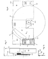
- a protective device 1 for a traction mechanism drive 2 is shown.
- the traction mechanism drive 2 essentially has a traction sheave 2.1 with an axis of rotation 2.3, over which traction means 9 run or via which the traction means 9 are mainly driven by frictional engagement.
- the traction means 9 are designed as steel cables for a lift, not shown.
- the traction sheave 2.1 is mounted at least partially on a support 2.2 via a receptacle, not shown for reasons of clarity. About the carrier 2.2, the forces acting on the traction sheave 2.1 forces are directed into a foundation, not shown.
- the steel cables 9 wrap the traction sheave 2.1 in an angular range between 135 ° and 180 °.
- the two areas in which the steel cables 9 can run on the traction sheave 2.1 is a major source of danger.
- a protective device 1 which covers the two danger areas and minimizes the gap between the protective device 1 and the traction sheave 2.1.
- a substantially U-shaped protective claw 6, 6 ' is provided which surrounds the steel cables 9 and the traction sheave 2.1 U-shaped and rests with very little margin on the traction sheave 2.1.
- the protective device 1, 1 ' is constructed as shown in the figures such that it can be easily and quickly mounted on numerous different traction sheaves 2.1.
- the protective device 1, 1 'of at least four members, namely a base plate 3, 3', a receptacle 4, 4 ', a sliding element 5, 5' and a protective claw 6, 6 ', as in FIGS. 2 and 3 shown enlarged in operative connection with each other.
- the base plate 3 is fixed as a first member on the support 2.2 and is displaceable in the direction of a longitudinal axis 1T of the carrier 2.2 and at different positions by means of retaining bolts 7 can be fixed. Due to the displaceability of the base plate 3, the protective device 1 can be adapted to the diameter of a traction sheave 2.1.
- a receptacle 4 is provided, which can be fixed to the base plate 3.
- the receptacle 4 is displaceable over several provided in the base plate 3 and in the receptacle 4 slots or holes 3.1, 4.1 in a direction perpendicular to the longitudinal axis 1T and fixed by means of retaining bolts 7 in any position.
- the sliding element 5 On the receptacle 4, the sliding element 5 is provided, which can be fixed to the receptacle 4.
- the sliding element 5 is slidable over several provided in the receptacle 4 and in the sliding element 5 slots 4.2, 5.1 in a direction perpendicular to the longitudinal axis 1T and perpendicular to the direction of displacement of the receptacle 4 with respect to the base plate 3 and fixed by means of retaining pin 7 in any position ,
- the L-shaped design of the sliding element 5 has the advantage that the base plate 3 as shown in Fig. 4 illustrates arranged in the direction of the longitudinal axis 1T of the carrier 2.2 in front of the traction sheave 2.1 and the protection device 1 can be adapted to the circular shape of the traction sheave 2.1. It is additionally advantageous that the base plate 3 due to their arrangement in front of the traction sheave 2.1 also reduces the risk of injury and accident.
- This embodiment can be simplified in that instead of the oblong holes in one of the links 3 to 6 a plurality of holes are provided and the individual members 3 to 6 can be staggered according to the spacing of the holes to each other.
- the displacement and the displacement is equal within the meaning of the invention.
- a protective claw 6 is provided with a U-shaped cross-sectional profile having two flanks u1, u2.
- the protective claw 6 can be fixed and adjusted via a mounting point M1 on the sliding element 5.
- the protective claw 6 is for this purpose mounted pivotably about a provided in a bore 6.1 of the protective claw 6 and in the sliding element 5 pivot pin 8 and a provided in the sliding element 5 semicircular slot 5.2 in any pivot position with the help of a provided in a bore 7.1 of the protective claw 6 retaining pin 7 can be fixed.
- the protective claw 6 is translationally adjustable in three mutually perpendicular directions in space and additionally mounted pivotably about one of the spatial axes.
- the universal applicability is increased by the fact that the approximately same protection device 1 can be used on both opposite sides of the traction sheave 2.1.
- the protective device 1 as shown in Fig. 1 in a first position P1 and in a second position P2 can be used.
- the symmetrically constructed protective claws 6, 6 ' have a first and a second mounting point M1.
- two holes 7.1 are provided for the retaining bolt 7 and a third bore 6.1 for the pivot pin 8.
- the retaining pin 7 can be arranged in two different holes 7.1 within the semicircular slot 5.2, the protective claw 6 can be set in several positions up to 360 ° twisted about the pivot pin 8 around.
- a total of three holes 6.2, 7.2 are arranged for the second position P2 at the second mounting point M2.
- the two sets of holes are each arranged in a flank u1, u2.
- the base plates 3, 3 ', the receptacles 4, 4' and the sliding elements 5, 5 'as shown in FIG. 1 can be used on both sides of the traction sheave 2.1.
- the sliding elements 5, 5 'as shown in FIG. 2 shown offset by 180 ° to the receptacle 4 are attached.
- Two identical sliding elements 5, 5 'with corresponding holes and slots are provided in a further, not shown embodiment.
- the flexible use of the protective device 1 is also increased by the fact that the protective claw 6 is adjustable in its width bS, so that the distance between the two flanks u1, u2 varies.
- the U-shaped protective claw 6 is formed of two interconnected L-shaped profiles, which are designed to be displaceable parallel to each other. As a result, as shown in FIGS. 4 and 5, the protective claw 6 can be adjusted to the width of the traction sheave 2.1.
- the protective claw 6 is adapted to the curvature of the traction sheave 2.1 in the circumferential direction to the axis of rotation 2.3.
- both the two flanks u1, u2 and the connecting element of the two flanks u1, u2 can be adapted to the curvature.
- FIGS. 5a to 5h show the four left-hand position with respect to a traction sheave 2.1 and FIGS. 5e to 5h show the four right-hand position of the protective device 1.
- the protective claw 6 is above the axis of rotation 2.3 Traction sheave 2.1 arranged.
- FIGS. 5b and 5d corresponding to 5f and 5h below.
- Fig. 6 the arrangement of two protective devices 1, 1 'with two mudguards 10, 10' is shown in simplified form.
- the respective fender 10 ' has a first recess 10.1', with the fender 10 'rests on the receptacle 4'.
- a part of the profile of the receptacle 4 ' is inserted into the first recess 10.1' for this purpose.
- the first recess 10.1 thus serves to set up the protective plate 10 on the receptacle 4, so that the weight of the protective plate 10 is supported by the protective device 1.
- the adjustment of the guard plate 10 during assembly and the attachment itself is simplified due to the non-secure own weight.
- first recess 10.1 By the first recess 10.1 also shown as in Fig. 7 tab 10.4 is formed on the fender 10, by means of which the fender 10 is attached to the receptacle 4. As a result, the first recess 10.1 fulfills two tasks simultaneously.
- the tab 10.4 is generated by folding a portion of the guard plate 10 and is arranged offset parallel to the main surface of the guard plate 10.
- the fender 10 has a second recess 10.2, is created by the free space for the shaft of the traction sheave 2.1.
- the size of the second recess 10.2 is dimensioned so that the same fender 10 can be used with traction sheaves 2.1 with different diameters.
- two mudguards 10, 10 ' which overlap above the axis of rotation 2.3, is maintained by the inventive design of the free space for the shaft of the traction sheave 2.1.
- the two mudguards 10, 10 ' are joined together in the area in which they overlap and lie as a total protection plate on the two receptacles 4, 4'.
- the second receptacle 4 ' is not shown in Fig. 6.
- the fender 10 is formed of perforated plate.
- the holes are shown in different areas of the mudguard 10 hinted. The attachment of the mudguard 10 thus requires no separate holes, since the holes are used.
- a cover 10.3 formed as a cover is provided in the upper region, which forms a horizontal region of the protective plate 10. By this bending 10.3 becomes in radial direction to the traction sheave 2.1 the area above the protective claw 6 protected.
- the cover may be formed as shown in Fig. 7a as a separately mounted hood 10.3.
- the hood 10.3 is mounted pivotably about an axis 10.5 parallel to the axis of rotation 2.3.
- the hood 10.3 additionally allows a test of the ropes when it is opened from the horizontal to the vertical position.
Landscapes
- Engineering & Computer Science (AREA)
- Mechanical Engineering (AREA)
- Civil Engineering (AREA)
- Structural Engineering (AREA)
- Soil Working Implements (AREA)
- Emergency Lowering Means (AREA)
- Pulleys (AREA)
- Valve-Gear Or Valve Arrangements (AREA)
- Devices For Conveying Motion By Means Of Endless Flexible Members (AREA)
- Component Parts Of Construction Machinery (AREA)
- Transmission Devices (AREA)
- Friction Gearing (AREA)
Abstract
Description
- Die Erfindung bezieht sich auf eine Schutzvorrichtung für den Ein- oder Auslaufbereich eines Zugmittels an einer Treibscheibe oder Umlenkrolle eines an einem Träger gelagerten Zugmittelantriebs, mit einer Schutzkralle, wobei die Schutzkralle über eine Haltevorrichtung gelagert ist.
- Es sind bereits zahlreiche solcher Schutzvorrichtungen mit einer Schutzkralle für Zugmittelantriebe bekannt.
- Der Erfindung liegt die Aufgabe zugrunde, eine Schutzvorrichtung derart auszubilden und anzuordnen, dass sie an verschiedenen Modellen von Zugmittelantrieben montiert werden kann und die Sicherheit erhöht.
- Gelöst wird die Aufgabe erfindungsgemäß dadurch, dass die Haltevorrichtung mindestens eine an dem Träger versetz- und/oder verschiebbar anzuordnende Basisplatte, mindestens eine an der Basisplatte versetz- und/oder verschiebbar angeordnete Aufnahme und mindestens ein an der Aufnahme versetz- und/oder verschiebbar angeordnetes Schiebeelement aufweist, wobei die Schutzkralle mittel und/oder unmittelbar am Schiebeelement schwenk- und/oder versetzbar angeordnet ist.
- Durch eine solche mehrgliedrige Ausbildungsweise kann die Schutzvorrichtung nicht nur im Vorfeld in gewissen Bereichen flexibel an die Gegebenheiten des jeweiligen Zugmittelantriebs angepasst, sondern auch vor Ort der Montage manuell angepasst werden. Die einzelnen Glieder der Haltevorrichtung können unabhängig von dem Zugmittelantrieb und unabhängig voneinander hergestellt werden und weisen jeweils einen in ihrer Grundform einfachen und konventionellen Aufbau auf.
- Vorteilhaft ist es hierzu, dass die Basisplatte mindestens in Richtung einer Längsachse des Trägers versetz- und/oder verschiebbar gelagert und festsetzbar ist. Dadurch wird gewährleistet, dass die Schutzvorrichtung universell an fast allen Arten von Zugmittelantrieben einsetzbar ist, da fast alle Zugmittelantriebe auf Trägern gelagert sind. Eine speziell Anpassung der Haltevorrichtung an den Aufbau des Zugmittelantriebs entfällt.
- Es ist ferner vorgesehen, die Basisplatte auf einem Betonsockel oder einem ähnlichen Fundament zu befestigen, dass nicht unbedingt als Lager für den Zugmittelantrieb dienen muss. Diese Lösung umfasst somit nicht nur eine in ihrer Größe einstellbare universelle Schutzkralle und ihre unmittelbare Befestigung am Zugmittelantrieb sondern auch eine universelle Haltevorrichtung, die losgelöst von den geometrischen Gegebenheiten des Zugmittelantriebs einsetzbar ist.
- Eine zusätzliche Möglichkeit ist gemäß einer Weiterbildung, dass die Basisplatte und/oder die Aufnahme mindestens ein Langloch und/oder eine Bohrung für mindestens einen ersten Haltebolzen aufweisen, über den die Aufnahme an der Basisplatte befestigbar ist, und die Aufnahme relativ zur Basisplatte stufenlos oder in Stufen verstellbar und festsetzbar ist. Die Basisplatte ist meist parallel zur Drehachse der Treibscheibe ausgerichtet, sodass die Aufnahme durch das Langloch in Bezug zu der Treibscheibe verschoben und befestigt werden kann. Dadurch ist zusätzlich zur Basisplatte auch die Aufnahme als zweites Glied der Haltevorrichtung verstellbar.
- Ferner ist es vorteilhaft, dass die Aufnahme und/oder das Schiebeelement mindestens ein Langloch und/oder eine Bohrung für mindestens einen zweiten Haltebolzen aufweisen, über den das Schiebeelement an der Aufnahme befestigbar ist, und das Schiebeelement relativ zur Aufnahme stufenlos oder in Stufen verstellbar und festsetzbar ist. Dadurch wird die Verstellbarkeit des dritten Gliedes der Haltevorrichtung gewährleistet. Die drei Glieder lassen sich somit in allen drei rechtwinklig zueinander ausgerichteten Raumrichtungen verschieben und festsetzen.
- Ausgehend von der Längsachse des Trägers, in deren Richtung die Basisplatte verstellbar ist, ist die Aufnahme in einer Richtung rechtwinklig zur Längsachse des Trägers und das Schiebeelement in einer Richtung rechtwinklig zur Verschieberichtung der Aufnahme verschiebbar. Bei entsprechender Dimensionierung der Verschiebewege, lässt sich die Schutzkralle ausgehend vom Träger oder dem Fundament an jeden beliebige Zugmittelantrieb anpassen.
- Ergänzend ist es vorteilhaft, dass das Schiebeelement und/oder die Schutzkralle mindestens ein Langloch für einen dritten Haltebolzen und/oder mindestens eine Bohrung für einen Schwenkbolzen aufweisen, über den die Schutzkralle an dem Schiebeelement befestigbar ist, und die Schutzkralle gegenüber dem Schiebeelement schwenkbar verstellbar und festsetzbar ist. Dadurch kann das eigentliche, den Schutz bildende vierte Glied, nämlich die Schutzkralle, an den Verlauf der Zugmittel angepasst werden. Der Schwenkbolzen bildet eine Schwenkachse. In Umfangsrichtung um die Schwenkachse lässt sich die Schutzkralle durch den Haltebolzen festsetzen, der in einem teilkreisförmigen Langloch geführt ist. Neben der in Richtung der drei Raumkoordinaten translatorischen Verstellbarkeit ist durch die Möglichkeit des Verschwenkens ein vierter Freiheitsgrad geschaffen, der die universelle Einstellbarkeit an viele verschiedene Zugmittelantriebe gewährleistet.
- Es ist in vorteilhafter Weise vorgesehen, dass die Schutzkralle zumindest zweiteilig ausgebildet ist, ein U-förmiges Querschnittsprofil mit zwei Flanken und mit einer Breite aufweist und das U-förmige Querschnittsprofil in seiner Breite verstellbar ausgebildet ist. Zugmittelantriebe unterscheiden sich im Durchmesser der Treibscheiben und in der Anzahl der Zugmittel, die nebeneinander auf einer Treibscheibe geführt werden. Mit zunehmender Anzahl der Zugmittel werden die Treibscheiben breiter. Die im Wesentlichen U-förmige Schutzkralle umschließt die Treibscheibe und die Zugmittel, wobei die beiden Flanken jeweils außen parallel zur Treibscheibe unmittelbar neben der Treibscheibe angeordnet werden. Durch die Verstellbarkeit der Breite der Schutzkralle, kann diese an unterschiedliche breite Treibscheiben angepasst werden. Je enger die Schutzkralle an der Treibscheibe und den Zugmitteln anliegt, desto sicherer ist die Schutzvorrichtung, sodass die Einstellbarkeit der Breite die Sicherheit der Schutzvorrichtung erhöht.
- Von besonderer Bedeutung ist für die vorliegende Erfindung, dass die Position der Schutzkralle mit Bezug zu einer Drehachse der Treibscheibe in radialer Richtung, in axialer Richtung und/oder in Umfangsrichtung verstellbar ist. Die zuvor beschriebene viergliedrige Ausbildungsweise gewährleistet die notwendige universelle Verstellbarkeit.
- Im Zusammenhang mit der erfindungsgemäßen Ausbildung und Anordnung ist es von Vorteil, dass das Schiebeelement eine im Wesentlichen L-förmige Grundform mit einem ersten Schenkel und einem zweiten Schenkel aufweist, wobei die Aufnahme am ersten Schenkel und die Schutzkralle am zweiten Schenkel angeordnet werden kann. Die L-förmige Gestaltung hat den Vorteil, dass das Schiebeelement relativ kurz ausgebildet werden kann, da die Schutzkralle über den zweiten Schenkel neben der Verschiebeeinrichtung für die Aufnahme und nicht in Flucht der Verschiebeeinrichtung angeordnet werden kann. Die Länge des Schiebeelements wird somit ausschließlich durch die Länge der Langlöcher zur Verstellung an der Aufnahme in vertikaler Richtung festgelegt. Ferner hat die L-Form den wesentlichen Vorteil, dass die Basisplatte und die Aufnahme in radialer Richtung zur Drehachse der Treibscheibe in Bezug zur Schutzkralle versetzt angeordnet sind. Dadurch können die drei Glieder der Haltevorrichtung, nämlich die Aufnahme, das Schiebeelement und die Schutzkralle an die Kreisform der Treibscheibe angepasst werden. Die Basisplatte ragt in einer Richtung parallel zur Drehachse über den Träger hinaus und ist in radialer Richtung zur Drehachse vor der Treibscheibe angeordnet.
- Vorteilhaft ist es auch, dass das Schiebeelement in einer ersten Position und in mindestens einer gegenüber der ersten Position um 180° gedrehten zweiten Position an der Aufnahme befestigbar ist. Dadurch wird erreicht, dass das gleiche Schiebeelement auf beiden gegenüberliegenden Seiten der Treibscheibe zum Einsatz kommen kann. Durch die L-Form bleibt die für diesen Wechsel erforderliche Symmetrie des Schiebeelements erhalten.
- Außerdem ist es vorteilhaft, dass eine Flanke zumindest zwei verschiedene Montagestellen für die mittel- oder unmittelbare Montage an das Schiebeelement aufweist und/oder die Schutzkralle in mindestens vier um jeweils 90° versetzte Positionen über eine Montagestelle am Schiebeelement festsetzbar ist. Je nach Verlauf der Zugmittel und der Grö-ße des Durchmessers der Treibscheibe kann ein und dieselbe Schutzkralle von links oder von rechts an die Treibscheibe herangeführt und auch oberhalb oder unterhalb der Drehachse positioniert werden. Die Schutzvorrichtung kann somit in insgesamt acht verschiedenen Varianten montiert werden.
- Eine weitere zusätzliche Möglichkeit ist gemäß einer Weiterbildung, dass die Schutzvorrichtung zusätzlich ein erstes Schutzblech aufweist, dass zumindest teilweise an die Schutzvorrichtung montierbar ist und das Schutzblech in einer Richtung parallel zur Drehachse zumindest teilweise vor der Schutzkralle und zumindest teilweise vor der Treibscheibe angeordnet werden kann. Dadurch wird erreicht, dass die Sicherheit der Schutzvorrichtung weiter erhöht wird, da auch der Bereich zwischen der Schutzkralle und der Treibscheibe durch das Schutzblech abgedeckt wird. Die Universalität bleibt erhalten, da das Schutzblech an der nachträglich anbringbare Schutzvorrichtung befestigt wird und die Abmessungen des Schutzblechs derart gewählt werden können, dass es an fast alle Größen von Treibscheiben passt.
- Das Schutzblech ist in vorteilhafter Weise aus Gründen des Gewichtes und der einfachen Montage aus Lochblech gebildet, sodass die vorhandenen Löcher anstatt separate Bohrungen zum verschrauben oder vernieten verwendet werden können.
- Ferner ist es vorteilhaft, dass zwei an einer Treibscheibe gegenüberliegend angeordnete Schutzvorrichtungen vorgesehen sind und die zweite Schutzvorrichtung ein zweites Schutzblech aufweist, dass zumindest an die Schutzvorrichtung montierbar ist und auch das zweite Schutzblech in einer Richtung parallel zur Drehachse zumindest teilweise vor der Schutzkralle und zumindest teilweise vor der Treibscheibe angeordnet ist. Zwei Schutzbleche haben den Vorteil, dass die gesamte Treibscheibe in dem stirnseitig relevanten Bereich abgedeckt werden kann.
- Ergänzend ist es vorteilhaft, dass das Schutzblech an die Aufnahme und/oder an das Schiebeelement montierbar ist, wobei das Schutzblech eine erste Aussparung aufweist, in die die Aufnahme und/oder das Schiebeelement einführbar ist und/oder das Schutzblech auf die Schutzvorrichtung aufsetzbar ist. Die beiden, beidseitig der Treibscheibe angeordneten Schutzvorrichtungen dienen als Auflager für die beiden Schutzbleche, wobei die beiden Schutzbleche zu einem Gesamtschutzblech verbunden werden, das auf den beiden Schutzvorrichtungen aufliegt. Durch die erste Aussparung wird das gesamte Gewicht der Schutzbleche auf die Schutzvorrichtungen übertragen, sodass das Schutzblech leichter justiert werden kann und die Befestigung des Schutzblechs entsprechend kleiner dimensionierbar ist.
- Es ist in vorteilhafter Weise vorgesehen, dass das Schutzblech eine zweite Aussparung aufweist, in der die Drehachse des Treibscheibe angeordnet werden kann und sich bei der Anordnung von zwei Schutzblechen die beiden zweiten Aussparungen im montierten Zustand der beiden Schutzbleche zumindest teilweise überdecken. Durch die zweite Aussparung wird erreicht, dass die beiden rechts und links angeordneten Schutzbleche überlappt werden können und dennoch eine Öffnung für die Welle der Treibscheibe zur Verfügung steht. Da es auf die Breite der dadurch gebildeten Öffnung im Bereich von Zentimetern nicht wesentlich ankommt, können gleiche Schutzbleche für verschiedene Durchmesser von Treibscheiben verwendet werden. Es bleibt nur zu beachten, dass die durch die beiden zweiten Aussparungen gebildete Öffnung zumindest breiter als die Welle der Treibscheibe ist.
- Von besonderer Bedeutung ist für die vorliegende Erfindung, dass das Schutzblech zumindest teilweise rechtwinklig zur Drehachse bzw. vertikal angeordnet ist und im oberen Bereich eine Abdeckung aufweist, die parallel zur Drehachse bzw. horizontal angeordnet ist. Dadurch wird erreicht, dass der Schutz der Schutzvorrichtung in radialer Richtung zur Drehachse der Treibscheibe auf den oberen Bereich der Treibscheibe erweitert werden kann, der nach oben hin an den Bereich der Schutzkralle anschließt.
- Hierzu ist es vorteilhaft, dass die Abdeckung als Abkantung oder als separat angebrachte Haube ausgebildet ist, wobei die Haube um eine Achse parallel zur Drehachse schwenkbar gelagert ist. Bei der Abkantung kann vorteilhaft das Schutzblech bei entsprechend größerer Dimensionierung benutzt werden. Die Haube lässt sich zusätzlich eine Prüfung der Seile zu.
- Weitere Vorteile und Einzelheiten der Erfindung sind in den Patentansprüchen und in der Beschreibung erläutert und in den Figuren dargestellt. Es zeigt:
- Figur 1
- eine perspektivische Darstellung eines Zugmittelantriebs mit einer Schutzvorrichtung;
- Figur 2
- eine perspektivische Darstellung einer Schutzvorrichtung in einer ersten Position;
- Figur 3
- eine perspektivische Darstellung einer Schutzvorrichtung in einer zweiten Position;
- Figur 4
- eine Seitenansicht auf den Zugmittelantrieb gemäß Fig. 1;
- Figur 5 a - g
- eine Darstellung der Schutzvorrichtung in acht verschiedenen Varianten.
- Figur 6
- eine Seitenansicht von zwei Schutzvorrichtungen mit zwei Schutzblechen;
- Figur 7
- eine vereinfachte Frontansicht gemäß Fig. 6;
- Figur 7a
- eine schwenkbare Abdeckung gemäß Fig. 7.
- In Fig. 1 ist eine Schutzvorrichtung 1 für einen Zugmittelantrieb 2 dargestellt. Der Zugmittelantrieb 2 weist im Wesentlichen eine Treibscheibe 2.1 mit einer Drehachse 2.3 auf, über die Zugmittel 9 laufen bzw. über die die Zugmittel 9 hauptsächlich reibschlüssig angetrieben werden. Die Zugmittel 9 sind als Stahlseile für einen nicht dargestellten Aufzug ausgebildet. Die Treibscheibe 2.1 ist über eine aus Gründen der Übersichtlichkeit nicht dargestellte Aufnahme zumindest teilweise auf einem Träger 2.2 gelagert. Über den Träger 2.2 werden die an der Treibscheibe 2.1 wirkenden Kräfte in ein nicht dargestelltes Fundament geleitet.
- Die Stahlseile 9 umschlingen die Treibscheibe 2.1 in einem Winkelbereich zwischen 135° und 180°. Dabei stellt je nach Drehrichtung der Treibscheibe 2.1 die beiden Bereiche, in denen die Stahlseile 9 an die Treibscheibe 2.1 laufen können eine große Gefahrenquelle dar. In diesen Bereichen besteht erhöhte Verletzungs- und Unfallgefahr, da durch die Drehbewegung der Treibscheibe 2.1 Gegenstände selbsthemmend zwischen die Stahlseile 9 und die Treibscheibe 2.1 gefördert werden.
- Die Gefahr wird durch eine Schutzvorrichtung 1 gemindert, die die beiden Gefahrenbereiche abdeckt und den Spalt zwischen der Schutzvorrichtung 1 und der Treibscheibe 2.1 minimiert. Hierzu ist beidseitig der Treibscheibe (2.1) eine im Wesentlichen U-förmige Schutzkralle 6, 6' vorgesehen, die die Stahlseile 9 und die Treibscheibe 2.1 U-förmig umschließt und mit äußerst wenig Spielraum an der Treibscheibe 2.1 anliegt.
- Die Schutzvorrichtung 1, 1' ist wie in den Figuren dargestellt derart aufgebaut, dass diese einfach und schnell an zahlreiche unterschiedliche Treibscheiben 2.1 montierbar ist. Hierzu besteht die Schutzvorrichtung 1, 1' aus mindestens vier Gliedern, nämlich eine Basisplatte 3, 3', eine Aufnahme 4, 4', ein Schiebeelement 5, 5' und eine Schutzkralle 6, 6', die wie in Fig. 2 und 3 vergrößert dargestellt miteinander in Wirkverbindung stehen.
- Die Basisplatte 3 wird als erstes Glied auf dem Träger 2.2 befestigt und ist in Richtung einer Längsachse 1T des Trägers 2.2 verschiebbar und an verschiedenen Positionen mit Hilfe von Haltebolzen 7 festsetzbar. Durch die Verschiebbarkeit der Basisplatte 3 kann die Schutzvorrichtung 1 an den Durchmesser einer Treibscheibe 2.1 angepasst werden.
- Auf der Basisplatte 3 ist eine Aufnahme 4 vorgesehen, die an der Basisplatte 3 festgesetzt werden kann. Die Aufnahme 4 ist über mehrere in der Basisplatte 3 und in der Aufnahme 4 vorgesehene Langlöcher bzw. Bohrungen 3.1, 4.1 in einer Richtung rechtwinklig zur Längsachse 1T verschiebbar und mit Hilfe von Haltebolzen 7 in beliebiger Position festsetzbar.
- An der Aufnahme 4 ist das Schiebeelement 5 vorgesehen, das an der Aufnahme 4 festgesetzt werden kann. Das Schiebeelement 5 ist über mehrere in der Aufnahme 4 und im Schiebeelement 5 vorgesehene Langlöcher 4.2, 5.1 in einer Richtung rechtwinklig zur Längsachse 1T und rechtwinklig zur Verschieberichtung der Aufnahme 4 in Bezug auf die Basisplatte 3 verschiebbar und mit Hilfe von Haltebolzen 7 in beliebiger Position festsetzbar.
- Die L-förmige Ausbildung des Schiebeelements 5 hat den Vorteil, dass die Basisplatte 3 wie in Fig. 4 verdeutlicht in Richtung der Längsachse 1T des Trägers 2.2 vor der Treibscheibe 2.1 angeordnet und die Schutzvorrichtung 1 an die Kreisform der Treibscheibe 2.1 angepasst werden kann. Hierbei ist zusätzlich vorteilhaft, dass die Basisplatte 3 aufgrund ihrer Anordnung vor der Treibscheibe 2.1 ebenfalls die Verletzungs- und Unfallgefahr mindert.
- Diese Ausbildungsform kann dadurch vereinfacht werden, dass anstatt der Langlöcher in einem der Glieder 3 bis 6 mehrere Bohrungen vorgesehen sind und die einzelnen Glieder 3 bis 6 entsprechend dem Abstand der Bohrungen zueinander gestuft versetzt werden können. Das Versetzen und das Verschieben ist im Sinne der Erfindung gleichgestellt.
- An dem Schiebeelement 5 ist eine Schutzkralle 6 mit einem U-förmigen Querschnittsprofil vorgesehen, das zwei Flanken u1, u2 aufweist. Die Schutzkralle 6 kann über eine Montagestelle M1 an dem Schiebeelement 5 festgesetzt und verstellt werden kann. Die Schutzkralle 6 ist hierzu um einen in einer Bohrung 6.1 der Schutzkralle 6 und in dem Schiebeelement 5 vorgesehenen Schwenkbolzen 8 schwenkbar gelagert und über ein in dem Schiebeelement 5 vorgesehenes halbkreisförmiges Langloch 5.2 in einer beliebigen Schwenkposition mit Hilfe von einem in einer Bohrung 7.1 der Schutzkralle 6 vorgesehenen Haltebolzen 7 festsetzbar.
- Somit ist die Schutzkralle 6 in drei zueinander rechtwinklig angeordneten Raumrichtungen translatorisch verstellbar und zusätzlich um eine der Raumachsen schwenkbar gelagert. Dadurch wird eine einfache Anpassung an verschiedene Treibscheiben 2.1 und entsprechende örtliche Gegebenheiten möglich.
- Die universelle Einsetzbarkeit wird dadurch erhöht, dass die annähernd gleiche Schutzvorrichtung 1 auf beiden gegenüberliegenden Seiten der Treibscheibe 2.1 eingesetzt werden kann. Hierzu ist die Schutzvorrichtung 1 wie in Fig. 1 dargestellt in einer ersten Position P1 und in einer zweiten Position P2 einsetzbar. Dies wird dadurch erreicht, dass die symmetrisch aufgebauten Schutzkrallen 6, 6' eine erste und eine zweite Montagestelle M1 aufweisen. An der ersten Montagestelle M1 sind zwei Bohrungen 7.1 für den Haltebolzen 7 und eine dritte Bohrung 6.1 für den Schwenkbolzen 8 vorgesehen. Dadurch dass der Haltebolzen 7 in zwei verschiedenen Bohrungen 7.1 innerhalb des halbkreisförmigen Langlochs 5.2 angeordnet werden kann, kann die Schutzkralle 6 in mehreren Positionen bis zu 360° verdreht um den Schwenkbolzen 8 herum festgesetzt werden.
- Entsprechend sind an der zweiten Montagestelle M2 auch insgesamt drei Bohrungen 6.2, 7.2 für die zweite Position P2 angeordnet. Die beiden Bohrungssätze sind jeweils in einer Flanke u1, u2 angeordnet.
- Ferner können die wie in Fig. 1 dargestellten Basisplatten 3, 3', die Aufnahmen 4, 4' und die Schiebeelemente 5, 5' auf beiden Seiten der Treibscheibe 2.1 eingesetzt werden. Hierzu können die Schiebeelemente 5, 5' wie in Fig. 2 dargestellt jeweils um 180° versetzt an der Aufnahme 4 befestigt werden. Zwei gleiche Schiebeelemente 5, 5' mit entsprechenden Bohrungen und Langlöchern sind in einem weiteren, nicht dargestellten Ausführungsbeispiel vorgesehen.
- Der flexible Einsatz der Schutzvorrichtung 1 wird zudem dadurch erhöht, dass die Schutzkralle 6 in ihrer Breite bS verstellbar ist, sodass der Abstand der beiden Flanken u1, u2 variiert. Wie in Fig. 2 dargestellt ist die U-förmige Schutzkralle 6 aus zwei miteinander verbundenen L-förmigen Profilen gebildet, die parallel zueinander verschiebbar ausgebildet sind. Dadurch kann wie in Fig. 4 und 5 verdeutlicht die Schutzkralle 6 an die Breite der Treibscheibe 2.1 angepasst werden.
- In einem nicht dargestellten Ausführungsbeispiel ist es von wesentlichem Vorteil für die Erfindung, dass die Schutzkralle 6 an die Krümmung der Treibscheibe 2.1 in Umfangsrichtung zur Drehachse 2.3 angepasst wird. Hierbei können sowohl die beiden Flanken u1, u2 als auch das Verbindungselement der beiden Flanken u1, u2 an die Krümmung angepasst werden.
- Anhand der Fig. 5a bis 5h wird die bezogen auf die möglichen Montagevarianten erreichte Universalität näher beschrieben. Ein und dieselbe Schutzvorrichtung 1 kann in insgesamt 8 Varianten montiert werden. Die Fig. 5a bis 5d zeigen die bezüglich einer Treibscheibe 2.1 vier linken Position und die Fig. 5e bis 5h die vier rechte Position der Schutzvorrichtung 1. In den Fig. 5a und 5c entsprechend 5e und 5g ist die Schutzkralle 6 oberhalb der Drehachse 2.3 der Treibscheibe 2.1 angeordnet. In den Fig. 5b und 5d entsprechend 5f und 5h unterhalb.
- In Richtung der Drehachse 2.3 sind die Schutzvorrichtung 1 gemäß den Fig. 5a und 5b entsprechend 5e und 5f vor der Treibscheibe 2.1 und in den Fig. 5c und 5d entsprechend 5g und 5h hinter der Treibscheibe 2.1, da die Schutzkralle 6 entsprechend vor oder hinter dem Schiebeelement 5 angeordnet ist.
- Details bezüglich der Befestigungen der Schutzkralle 6 am Schiebeelement 5, insbesondere das Langloch und die beiden Bohrungen 7.1 sind aufgrund der Übersichtlichkeit in Fig. 2 dargestellt.
- In Fig. 6 ist die Anordnung von zwei Schutzvorrichtungen 1, 1' mit zwei Schutzblechen 10, 10' vereinfacht dargestellt. Das jeweilige Schutzblech 10' weist eine erste Aussparung 10.1' auf, mit der das Schutzblech 10' auf der Aufnahme 4' aufliegt. Ein Teil des Profils der Aufnahme 4' ist hierzu in die erste Aussparung 10.1' eingesteckt.
- Die erste Aussparung 10.1 dient also dazu, das Schutzblech 10 auf die Aufnahme 4 aufzusetzen, sodass das Gewicht des Schutzbleches 10 durch die Schutzvorrichtung 1 getragen wird. Dadurch wird die Justierung des Schutzbleches 10 während der Montage und die Befestigung selbst aufgrund des nicht zu sichernden Eigengewichtes vereinfacht.
- Durch die erste Aussparung 10.1 wird zudem eine wie in Fig. 7 dargestellte Lasche 10.4 an dem Schutzblech 10 gebildet, mit Hilfe derer das Schutzblech 10 an der Aufnahme 4 befestigt wird. Dadurch erfüllt die erste Aussparung 10.1 zwei Aufgaben gleichzeitig. Die Lasche 10.4 wird durch Abkanten eines Bereiches des Schutzbleches 10 erzeugt und ist parallel versetzt zur Hauptfläche des Schutzblechs 10 angeordnet.
- Das Schutzblech 10 weist eine zweite Aussparung 10.2 auf, durch die Freiraum für die Welle der Treibscheibe 2.1 geschaffen wird. Die Größe der zweiten Aussparung 10.2 ist so dimensioniert, dass das gleiche Schutzblech 10 bei Treibscheiben 2.1 mit verschieden großen Durchmessern verwendet werden kann. Bei der vorstehend beschriebenen Verwendung von zwei Schutzblechen 10, 10', die oberhalb der Drehachse 2.3 überlappen, wird durch die erfindungsgemäße Ausbildung der Freiraum für die Welle der Treibscheibe 2.1 aufrecht erhalten. Die beiden Schutzbleche 10, 10' werden in dem Bereich, in dem sie sich überlappen aneinander gefügt und liegen als Gesamtschutzblech auf den beiden Aufnahmen 4, 4' auf. Die zweite Aufnahme 4' ist in Fig. 6 nicht dargestellt.
- Das Schutzblech 10 ist aus Lochblech gebildet. Die Löcher sind in verschiedenen Bereichen des Schutzblechs 10 andeutungsweise dargestellt. Die Befestigung des Schutzblechs 10 erfordert somit keine separaten Bohrungen, da die Löcher Verwendung finden. Die beiden Schutzbleche 10, 10' sind parallel zur Treibscheibe 2.1 vertikal ausgerichtet und schützen somit in Richtung der Drehachse 2.3 vor möglichen Gefahren. Entsprechend ist sowohl die Haltevorrichtung H als auch die Schutzkralle 6 sowie die Treibscheibe 2.1 hinter dem Schutzblech 10 angeordnet.
- In Fig. 7 wird diese Reihenfolge der Anordnung noch einmal vereinfacht dargestellt. Die einzelnen Bauteile sind aus Gründen der Übersicht beabstandet voneinander dargestellt. Zusätzlich zu der vertikalen Anordnung des Schutzblechs 10 ist eine als Abdeckung ausgebildete Abkantung 10.3 im oberen Bereich vorgesehen, die einen horizontalen Bereich des Schutzblechs 10 bildet. Durch diese Abkantung 10.3 wird in radialer Richtung zur Treibscheibe 2.1 der Bereich oberhalb der Schutzkralle 6 geschützt.
- Die Abdeckung kann wie in Fig. 7a dargestellt als separat angebrachte Haube 10.3 ausgebildet sein. Die Haube 10.3 ist um eine Achse 10.5 parallel zur Drehachse 2.3 schwenkbar gelagert. Die Haube 10.3 lässt zusätzlich eine Prüfung der Seile zu, wenn sie von der horizontalen in die vertikale Position geöffnet wird.
Claims (16)
- Schutzvorrichtung (1) für den Ein- oder Auslaufbereich eines Zugmittels (9) an einer Treibscheibe (2.1) oder Umlenkrolle eines an einem Träger (2.2) gelagerten Zugmittelantriebs (2), mit einer Schutzkralle (6), wobei die Schutzkralle (6) über eine Haltevorrichtung (H) gelagert ist,
dadurch gekennzeichnet,
dass die Haltevorrichtung (H)a) mindestens eine an dem Träger (2.2) versetz- und/oder verschiebbar anzuordnende Basisplatte (3),b) mindestens eine an der Basisplatte (3) versetz- und/oder verschiebbar angeordnete Aufnahme (4) undc) mindestens ein an der Aufnahme (4) versetz- und/oder verschiebbar angeordnetes Schiebeelement (5) aufweist, wobei die Schutzkralle (6) mittel und/oder unmittelbar am Schiebeelement (5) schwenk- und/oder versetzbar angeordnet ist. - Vorrichtung nach Anspruch 1,
dadurch gekennzeichnet,
dass die Basisplatte (3) mindestens in Richtung einer Längsachse (1T) des Trägers (2.2) versetz- und/oder verschiebbar gelagert und festsetzbar ist. - Vorrichtung nach Anspruch 1 oder 2,
dadurch gekennzeichnet,
dass die Basisplatte (3) und/oder die Aufnahme (4) mindestens ein Langloch (3.1) und/oder eine Bohrung (4.1) für mindestens einen ersten Haltebolzen (7) aufweisen, über den die Aufnahme (4) an der Basisplatte (3) befestigbar ist, und die Aufnahme (4) relativ zur Basisplatte (3) stufenlos oder in Stufen verstellbar und festsetzbar ist. - Vorrichtung nach einem der vorhergehenden Ansprüche,
dadurch gekennzeichnet,
dass die Aufnahme (4) und/oder das Schiebeelement (5) mindestens ein Langloch (4.2, 5.1) und/oder eine Bohrung für mindestens einen zweiten Haltebolzen (7) aufweisen, über den das Schiebeelement (5) an der Aufnahme (4) befestigbar ist, und das Schiebeelement (5) relativ zur Aufnahme (4) stufenlos oder in Stufen verstellbar und festsetzbar ist. - Vorrichtung nach einem der vorhergehenden Ansprüche,
dadurch gekennzeichnet,
dass das Schiebeelement (5) und/oder die Schutzkralle (6) mindestens ein Langloch (5.2) für einen dritten Haltebolzen (7) und/oder mindestens eine Bohrung (6.1) für einen Schwenkbolzen (8) aufweisen, über den die Schutzkralle (6) an dem Schiebeelement (5) befestigbar ist, und die Schutzkralle (6) gegenüber dem Schiebeelement (5) schwenkbar verstellbar und festsetzbar ist. - Vorrichtung nach einem der vorhergehenden Ansprüche,
dadurch gekennzeichnet,
dass die Schutzkralle (6) zumindest zweiteilig ausgebildet ist, ein U-förmiges Querschnittsprofil mit zwei Flanken (u1, u2) und mit einer Breite (bS) aufweist und das U-förmige Querschnittsprofil in seiner Breite (bS) verstellbar ausgebildet ist. - Vorrichtung nach einem der vorhergehenden Ansprüche,
dadurch gekennzeichnet,
dass die Position der Schutzkralle (6) mit Bezug zu einer Drehachse (2.3) der Treibscheibe (2.1) in radialer Richtung und/oder in Umfangsrichtung verstellbar ist. - Vorrichtung nach einem der vorhergehenden Ansprüche,
dadurch gekennzeichnet,
dass das Schiebeelement (5) eine im Wesentlichen L-förmige Grundform mit einem ersten Schenkel (5.3) und einem zweiten Schenkel (5.4) aufweist, wobei die Aufnahme (4) am ersten Schenkel (5.3) und die Schutzkralle (6) am zweiten Schenkel (5.4) angeordnet werden kann. - Vorrichtung nach einem der vorhergehenden Ansprüche,
dadurch gekennzeichnet,
dass das Schiebeelement (5) in einer ersten Position (P1) und in mindestens einer gegenüber der ersten Position (P1) um 180° gedrehten zweiten Position (P2) an der Aufnahme (4) befestigbar ist. - Vorrichtung nach einem der Ansprüche 6 bis 10,
dadurch gekennzeichnet,
dass eine Flanke (u1, u2) zumindest zwei verschiedene Montagestellen (M1, M2) für die mittel- oder unmittelbare Montage an das Schiebeelement (5) aufweist und/oder die Schutzkralle (6) in mindestens vier um jeweils 90° versetzte Positionen über eine Montagestelle (M1, M2) am Schiebeelement (5) festsetzbar ist. - Vorrichtung nach einem der vorhergehenden Ansprüche,
dadurch gekennzeichnet,
dass die Schutzvorrichtung (1) zusätzlich ein erstes Schutzblech (10) aufweist, das zumindest teilweise an die Schutzvorrichtung (1) montierbar ist, und das Schutzblech (10) in einer Richtung parallel zur Drehachse (2.3) zumindest teilweise vor der Schutzkralle (6) und zumindest teilweise vor der Treibscheibe (2.1) angeordnet werden kann. - Vorrichtung nach Anspruch 11,
dadurch gekennzeichnet,
dass zwei an einer Treibscheibe (2.1) gegenüberliegend angeordnete Schutzvorrichtungen (1, 1') vorgesehen sind und die zweite Schutzvorrichtung (1') ein zweites Schutzblech (10') aufweist, das zumindest an die Schutzvorrichtung (1') montierbar ist, und auch das zweite Schutzblech (10') in einer Richtung parallel zur Drehachse (2.3) zumindest teilweise vor der Schutzkralle (6') und zumindest teilweise vor der Treibscheibe (2.1) angeordnet ist. - Vorrichtung nach einem der Ansprüche 11 und 12,
dadurch gekennzeichnet,
dass das Schutzblech (10) an die Aufnahme (4) und/oder an das Schiebeelement (5) montierbar ist, wobei das Schutzblech (10) eine erste Aussparung (10.1) aufweist, in die die Aufnahme (4) und/oder das Schiebeelement (5) einführbar ist, und/oder das Schutzblech (10) auf die Schutzvorrichtung (1) aufsetzbar ist. - Vorrichtung nach Anspruch 13,
dadurch gekennzeichnet,
dass das Schutzblech (10) eine zweite Aussparung (10.2) aufweist, in der die Drehachse (2.3) der Treibscheibe (2.1) angeordnet werden kann und sich bei der Anordnung von zwei Schutzblechen (10, 10') die beiden zweiten Aussparungen (10.2, 10.2') im montierten Zustand der beiden Schutzbleche (10, 10') zumindest teilweise überdecken. - Vorrichtung nach Anspruch 14,
dadurch gekennzeichnet,
dass das Schutzblech (10) zumindest teilweise rechtwinklig zur Drehachse (2.3) bzw. vertikal angeordnet ist und im oberen Bereich eine Abdeckung (10.3) aufweist, die parallel zur Drehachse (2.3) bzw. horizontal angeordnet ist. - Vorrichtung nach Anspruch 15,
dadurch gekennzeichnet,
dass die Abdeckung (10.3) als Abkantung oder als separat angebrachte Haube ausgebildet ist, wobei die Haube um eine Achse parallel zur Drehachse (2.3) schwenkbar gelagert ist.
Applications Claiming Priority (1)
| Application Number | Priority Date | Filing Date | Title |
|---|---|---|---|
| DE102004060094A DE102004060094A1 (de) | 2004-12-13 | 2004-12-13 | Treibscheibenschutz |
Publications (2)
| Publication Number | Publication Date |
|---|---|
| EP1679283A1 true EP1679283A1 (de) | 2006-07-12 |
| EP1679283B1 EP1679283B1 (de) | 2008-02-13 |
Family
ID=36046876
Family Applications (1)
| Application Number | Title | Priority Date | Filing Date |
|---|---|---|---|
| EP05112074A Expired - Lifetime EP1679283B1 (de) | 2004-12-13 | 2005-12-13 | Treibscheibenschutz |
Country Status (3)
| Country | Link |
|---|---|
| EP (1) | EP1679283B1 (de) |
| AT (1) | ATE385991T1 (de) |
| DE (2) | DE102004060094A1 (de) |
Cited By (5)
| Publication number | Priority date | Publication date | Assignee | Title |
|---|---|---|---|---|
| CN104261235A (zh) * | 2014-10-23 | 2015-01-07 | 苏州新达电扶梯部件有限公司 | 一种可调节曳引机侧防护罩 |
| EP2480475B1 (de) | 2009-09-25 | 2018-03-21 | Kone Corporation | Hebemaschine und aufzugsystem |
| CN107840223A (zh) * | 2016-09-18 | 2018-03-27 | 崇友实业股份有限公司 | 可调式钢索保护屏蔽装置 |
| CN110550520A (zh) * | 2019-09-19 | 2019-12-10 | 广东工业大学 | 一种电梯主机用侧护罩 |
| WO2026052201A1 (en) * | 2024-09-03 | 2026-03-12 | Kone Corporation | Hoisting machine arrangement and elevator |
Families Citing this family (1)
| Publication number | Priority date | Publication date | Assignee | Title |
|---|---|---|---|---|
| CN107082346B (zh) * | 2017-05-17 | 2022-10-11 | 宁波欣达电梯配件厂 | 一种曳引机防护罩 |
Citations (2)
| Publication number | Priority date | Publication date | Assignee | Title |
|---|---|---|---|---|
| JPH05105365A (ja) * | 1991-10-18 | 1993-04-27 | Mitsubishi Denki Bill Techno Service Kk | エレベータ装置 |
| WO2004013029A1 (ja) * | 2002-08-06 | 2004-02-12 | Mitsubishi Denki Kabushiki Kaisha | エレベータ装置 |
-
2004
- 2004-12-13 DE DE102004060094A patent/DE102004060094A1/de not_active Ceased
-
2005
- 2005-12-13 AT AT05112074T patent/ATE385991T1/de active
- 2005-12-13 EP EP05112074A patent/EP1679283B1/de not_active Expired - Lifetime
- 2005-12-13 DE DE502005002822T patent/DE502005002822D1/de not_active Expired - Lifetime
Patent Citations (2)
| Publication number | Priority date | Publication date | Assignee | Title |
|---|---|---|---|---|
| JPH05105365A (ja) * | 1991-10-18 | 1993-04-27 | Mitsubishi Denki Bill Techno Service Kk | エレベータ装置 |
| WO2004013029A1 (ja) * | 2002-08-06 | 2004-02-12 | Mitsubishi Denki Kabushiki Kaisha | エレベータ装置 |
Non-Patent Citations (1)
| Title |
|---|
| PATENT ABSTRACTS OF JAPAN vol. 017, no. 459 (M - 1467) 23 August 1993 (1993-08-23) * |
Cited By (5)
| Publication number | Priority date | Publication date | Assignee | Title |
|---|---|---|---|---|
| EP2480475B1 (de) | 2009-09-25 | 2018-03-21 | Kone Corporation | Hebemaschine und aufzugsystem |
| CN104261235A (zh) * | 2014-10-23 | 2015-01-07 | 苏州新达电扶梯部件有限公司 | 一种可调节曳引机侧防护罩 |
| CN107840223A (zh) * | 2016-09-18 | 2018-03-27 | 崇友实业股份有限公司 | 可调式钢索保护屏蔽装置 |
| CN110550520A (zh) * | 2019-09-19 | 2019-12-10 | 广东工业大学 | 一种电梯主机用侧护罩 |
| WO2026052201A1 (en) * | 2024-09-03 | 2026-03-12 | Kone Corporation | Hoisting machine arrangement and elevator |
Also Published As
| Publication number | Publication date |
|---|---|
| ATE385991T1 (de) | 2008-03-15 |
| DE102004060094A1 (de) | 2006-06-14 |
| EP1679283B1 (de) | 2008-02-13 |
| DE502005002822D1 (de) | 2008-03-27 |
Similar Documents
| Publication | Publication Date | Title |
|---|---|---|
| EP1707420B1 (de) | Kühleranordnung | |
| EP1527242B1 (de) | Arbeitsbühne | |
| DE69902348T2 (de) | Biderektionale sperreinrichtung für absturzsicherung | |
| EP2531383B1 (de) | Gurtaufrollerrahmen | |
| DE102008059680A1 (de) | Vorrichtung zur Halterung einer Batterie | |
| EP0016317A1 (de) | Höhenverstellbare Anhängerkupplung | |
| DE69809031T3 (de) | Fahrzeugbeladungsvorrichtung | |
| DE2325753A1 (de) | Waermetauschvorrichtung fuer kraftanlagen insbesondere fuer brennkraftmaschinen | |
| EP1679283B1 (de) | Treibscheibenschutz | |
| DE102007048208A1 (de) | Lenksäule für ein Kraftfahrzeug | |
| DE102008014724A1 (de) | Schutzvorrichtung für Maschinen und / oder Anlagen | |
| DE60103594T2 (de) | Verkehrsleit- und Schutzplankenanordnung | |
| EP1965625A2 (de) | Varioträger | |
| EP1418296B1 (de) | Gesicherte Notentriegelungsvorrichtung sowie Verwendung derselben | |
| AT518917B1 (de) | Absturzsicherung | |
| DE102005011382B4 (de) | Fahrzeugrückhaltesystem zum Absichern von Fahrbahnen in einem Passagebereich und Leitschwellenelement für ein Fahrzeugrückhaltesystem | |
| DE10356220B4 (de) | Sicherungseinrichtung für befahrbare oder begehbare Flächen | |
| EP2532982A2 (de) | Vorrichtung zur Sicherung eines mittels Aufhängelaschen in einer mit Aufnahmeschlitz versehenen Konsole gehaltenen Heizkörpers | |
| EP3183159B1 (de) | Lenksäule für ein kraftfahrzeug | |
| DE202019102577U1 (de) | Klemmelement, Aufsatzleitpfosten und Aufsatzleitpfostenanordnung | |
| AT522872B1 (de) | Anbauelement zur Montage an einem Leitwandelement eines Fahrzeugrückhaltesystems | |
| DE102006025724B3 (de) | Vorrichtung zur Befestigung eines Flachbildschirms | |
| EP1817462B1 (de) | Aufhängung für eine schiene | |
| DE102016221524A1 (de) | Absturzsicherungseinrichtung | |
| EP1529885B1 (de) | Anpralldämpfer an Verkehrswegen |
Legal Events
| Date | Code | Title | Description |
|---|---|---|---|
| PUAI | Public reference made under article 153(3) epc to a published international application that has entered the european phase |
Free format text: ORIGINAL CODE: 0009012 |
|
| AK | Designated contracting states |
Kind code of ref document: A1 Designated state(s): AT BE BG CH CY CZ DE DK EE ES FI FR GB GR HU IE IS IT LI LT LU LV MC NL PL PT RO SE SI SK TR |
|
| AX | Request for extension of the european patent |
Extension state: AL BA HR MK YU |
|
| 17P | Request for examination filed |
Effective date: 20060607 |
|
| AKX | Designation fees paid |
Designated state(s): AT BE BG CH CY CZ DE DK EE ES FI FR GB GR HU IE IS IT LI LT LU LV MC NL PL PT RO SE SI SK TR |
|
| GRAP | Despatch of communication of intention to grant a patent |
Free format text: ORIGINAL CODE: EPIDOSNIGR1 |
|
| GRAS | Grant fee paid |
Free format text: ORIGINAL CODE: EPIDOSNIGR3 |
|
| GRAA | (expected) grant |
Free format text: ORIGINAL CODE: 0009210 |
|
| AK | Designated contracting states |
Kind code of ref document: B1 Designated state(s): AT BE BG CH CY CZ DE DK EE ES FI FR GB GR HU IE IS IT LI LT LU LV MC NL PL PT RO SE SI SK TR |
|
| REG | Reference to a national code |
Ref country code: GB Ref legal event code: FG4D Free format text: NOT ENGLISH |
|
| REG | Reference to a national code |
Ref country code: CH Ref legal event code: EP |
|
| REG | Reference to a national code |
Ref country code: IE Ref legal event code: FG4D Free format text: LANGUAGE OF EP DOCUMENT: GERMAN |
|
| REF | Corresponds to: |
Ref document number: 502005002822 Country of ref document: DE Date of ref document: 20080327 Kind code of ref document: P |
|
| PG25 | Lapsed in a contracting state [announced via postgrant information from national office to epo] |
Ref country code: ES Free format text: LAPSE BECAUSE OF FAILURE TO SUBMIT A TRANSLATION OF THE DESCRIPTION OR TO PAY THE FEE WITHIN THE PRESCRIBED TIME-LIMIT Effective date: 20080524 Ref country code: FI Free format text: LAPSE BECAUSE OF FAILURE TO SUBMIT A TRANSLATION OF THE DESCRIPTION OR TO PAY THE FEE WITHIN THE PRESCRIBED TIME-LIMIT Effective date: 20080213 Ref country code: IS Free format text: LAPSE BECAUSE OF FAILURE TO SUBMIT A TRANSLATION OF THE DESCRIPTION OR TO PAY THE FEE WITHIN THE PRESCRIBED TIME-LIMIT Effective date: 20080613 |
|
| PG25 | Lapsed in a contracting state [announced via postgrant information from national office to epo] |
Ref country code: SI Free format text: LAPSE BECAUSE OF FAILURE TO SUBMIT A TRANSLATION OF THE DESCRIPTION OR TO PAY THE FEE WITHIN THE PRESCRIBED TIME-LIMIT Effective date: 20080213 Ref country code: LV Free format text: LAPSE BECAUSE OF FAILURE TO SUBMIT A TRANSLATION OF THE DESCRIPTION OR TO PAY THE FEE WITHIN THE PRESCRIBED TIME-LIMIT Effective date: 20080213 Ref country code: PL Free format text: LAPSE BECAUSE OF FAILURE TO SUBMIT A TRANSLATION OF THE DESCRIPTION OR TO PAY THE FEE WITHIN THE PRESCRIBED TIME-LIMIT Effective date: 20080213 |
|
| REG | Reference to a national code |
Ref country code: IE Ref legal event code: FD4D |
|
| REG | Reference to a national code |
Ref country code: HU Ref legal event code: AG4A Ref document number: E003658 Country of ref document: HU |
|
| PG25 | Lapsed in a contracting state [announced via postgrant information from national office to epo] |
Ref country code: IE Free format text: LAPSE BECAUSE OF FAILURE TO SUBMIT A TRANSLATION OF THE DESCRIPTION OR TO PAY THE FEE WITHIN THE PRESCRIBED TIME-LIMIT Effective date: 20080213 Ref country code: DK Free format text: LAPSE BECAUSE OF FAILURE TO SUBMIT A TRANSLATION OF THE DESCRIPTION OR TO PAY THE FEE WITHIN THE PRESCRIBED TIME-LIMIT Effective date: 20080213 Ref country code: PT Free format text: LAPSE BECAUSE OF FAILURE TO SUBMIT A TRANSLATION OF THE DESCRIPTION OR TO PAY THE FEE WITHIN THE PRESCRIBED TIME-LIMIT Effective date: 20080714 Ref country code: SE Free format text: LAPSE BECAUSE OF FAILURE TO SUBMIT A TRANSLATION OF THE DESCRIPTION OR TO PAY THE FEE WITHIN THE PRESCRIBED TIME-LIMIT Effective date: 20080513 |
|
| PG25 | Lapsed in a contracting state [announced via postgrant information from national office to epo] |
Ref country code: RO Free format text: LAPSE BECAUSE OF FAILURE TO SUBMIT A TRANSLATION OF THE DESCRIPTION OR TO PAY THE FEE WITHIN THE PRESCRIBED TIME-LIMIT Effective date: 20080213 |
|
| PLBE | No opposition filed within time limit |
Free format text: ORIGINAL CODE: 0009261 |
|
| STAA | Information on the status of an ep patent application or granted ep patent |
Free format text: STATUS: NO OPPOSITION FILED WITHIN TIME LIMIT |
|
| 26N | No opposition filed |
Effective date: 20081114 |
|
| PG25 | Lapsed in a contracting state [announced via postgrant information from national office to epo] |
Ref country code: LT Free format text: LAPSE BECAUSE OF FAILURE TO SUBMIT A TRANSLATION OF THE DESCRIPTION OR TO PAY THE FEE WITHIN THE PRESCRIBED TIME-LIMIT Effective date: 20080213 |
|
| PG25 | Lapsed in a contracting state [announced via postgrant information from national office to epo] |
Ref country code: BG Free format text: LAPSE BECAUSE OF FAILURE TO SUBMIT A TRANSLATION OF THE DESCRIPTION OR TO PAY THE FEE WITHIN THE PRESCRIBED TIME-LIMIT Effective date: 20080513 Ref country code: EE Free format text: LAPSE BECAUSE OF FAILURE TO SUBMIT A TRANSLATION OF THE DESCRIPTION OR TO PAY THE FEE WITHIN THE PRESCRIBED TIME-LIMIT Effective date: 20080213 |
|
| PG25 | Lapsed in a contracting state [announced via postgrant information from national office to epo] |
Ref country code: MC Free format text: LAPSE BECAUSE OF NON-PAYMENT OF DUE FEES Effective date: 20081231 Ref country code: CY Free format text: LAPSE BECAUSE OF FAILURE TO SUBMIT A TRANSLATION OF THE DESCRIPTION OR TO PAY THE FEE WITHIN THE PRESCRIBED TIME-LIMIT Effective date: 20080213 |
|
| PG25 | Lapsed in a contracting state [announced via postgrant information from national office to epo] |
Ref country code: IT Free format text: LAPSE BECAUSE OF FAILURE TO SUBMIT A TRANSLATION OF THE DESCRIPTION OR TO PAY THE FEE WITHIN THE PRESCRIBED TIME-LIMIT Effective date: 20080213 |
|
| PG25 | Lapsed in a contracting state [announced via postgrant information from national office to epo] |
Ref country code: LU Free format text: LAPSE BECAUSE OF NON-PAYMENT OF DUE FEES Effective date: 20081213 |
|
| REG | Reference to a national code |
Ref country code: CH Ref legal event code: PL |
|
| PG25 | Lapsed in a contracting state [announced via postgrant information from national office to epo] |
Ref country code: TR Free format text: LAPSE BECAUSE OF FAILURE TO SUBMIT A TRANSLATION OF THE DESCRIPTION OR TO PAY THE FEE WITHIN THE PRESCRIBED TIME-LIMIT Effective date: 20080213 |
|
| PG25 | Lapsed in a contracting state [announced via postgrant information from national office to epo] |
Ref country code: CH Free format text: LAPSE BECAUSE OF NON-PAYMENT OF DUE FEES Effective date: 20091231 Ref country code: GR Free format text: LAPSE BECAUSE OF FAILURE TO SUBMIT A TRANSLATION OF THE DESCRIPTION OR TO PAY THE FEE WITHIN THE PRESCRIBED TIME-LIMIT Effective date: 20080514 Ref country code: LI Free format text: LAPSE BECAUSE OF NON-PAYMENT OF DUE FEES Effective date: 20091231 |
|
| REG | Reference to a national code |
Ref country code: FR Ref legal event code: PLFP Year of fee payment: 11 |
|
| REG | Reference to a national code |
Ref country code: FR Ref legal event code: PLFP Year of fee payment: 12 |
|
| PGFP | Annual fee paid to national office [announced via postgrant information from national office to epo] |
Ref country code: HU Payment date: 20161221 Year of fee payment: 12 Ref country code: DE Payment date: 20161213 Year of fee payment: 12 Ref country code: GB Payment date: 20161222 Year of fee payment: 12 Ref country code: SK Payment date: 20161212 Year of fee payment: 12 Ref country code: CZ Payment date: 20161123 Year of fee payment: 12 Ref country code: NL Payment date: 20161221 Year of fee payment: 12 |
|
| PGFP | Annual fee paid to national office [announced via postgrant information from national office to epo] |
Ref country code: FR Payment date: 20161222 Year of fee payment: 12 Ref country code: AT Payment date: 20161222 Year of fee payment: 12 Ref country code: BE Payment date: 20161221 Year of fee payment: 12 |
|
| REG | Reference to a national code |
Ref country code: DE Ref legal event code: R119 Ref document number: 502005002822 Country of ref document: DE |
|
| PG25 | Lapsed in a contracting state [announced via postgrant information from national office to epo] |
Ref country code: CZ Free format text: LAPSE BECAUSE OF NON-PAYMENT OF DUE FEES Effective date: 20171213 |
|
| REG | Reference to a national code |
Ref country code: NL Ref legal event code: MM Effective date: 20180101 |
|
| REG | Reference to a national code |
Ref country code: AT Ref legal event code: MM01 Ref document number: 385991 Country of ref document: AT Kind code of ref document: T Effective date: 20171213 |
|
| GBPC | Gb: european patent ceased through non-payment of renewal fee |
Effective date: 20171213 |
|
| REG | Reference to a national code |
Ref country code: SK Ref legal event code: MM4A Ref document number: E 3452 Country of ref document: SK Effective date: 20171213 |
|
| PG25 | Lapsed in a contracting state [announced via postgrant information from national office to epo] |
Ref country code: NL Free format text: LAPSE BECAUSE OF NON-PAYMENT OF DUE FEES Effective date: 20180101 |
|
| REG | Reference to a national code |
Ref country code: FR Ref legal event code: ST Effective date: 20180831 |
|
| REG | Reference to a national code |
Ref country code: BE Ref legal event code: MM Effective date: 20171231 |
|
| PG25 | Lapsed in a contracting state [announced via postgrant information from national office to epo] |
Ref country code: FR Free format text: LAPSE BECAUSE OF NON-PAYMENT OF DUE FEES Effective date: 20180102 Ref country code: DE Free format text: LAPSE BECAUSE OF NON-PAYMENT OF DUE FEES Effective date: 20180703 Ref country code: HU Free format text: LAPSE BECAUSE OF NON-PAYMENT OF DUE FEES Effective date: 20171214 |
|
| PG25 | Lapsed in a contracting state [announced via postgrant information from national office to epo] |
Ref country code: SK Free format text: LAPSE BECAUSE OF NON-PAYMENT OF DUE FEES Effective date: 20171213 Ref country code: BE Free format text: LAPSE BECAUSE OF NON-PAYMENT OF DUE FEES Effective date: 20171231 Ref country code: AT Free format text: LAPSE BECAUSE OF NON-PAYMENT OF DUE FEES Effective date: 20171213 Ref country code: GB Free format text: LAPSE BECAUSE OF NON-PAYMENT OF DUE FEES Effective date: 20171213 |