EP1679455A1 - Agencement d'un levier de commande pour une transmission automatique - Google Patents
Agencement d'un levier de commande pour une transmission automatique Download PDFInfo
- Publication number
- EP1679455A1 EP1679455A1 EP05100039A EP05100039A EP1679455A1 EP 1679455 A1 EP1679455 A1 EP 1679455A1 EP 05100039 A EP05100039 A EP 05100039A EP 05100039 A EP05100039 A EP 05100039A EP 1679455 A1 EP1679455 A1 EP 1679455A1
- Authority
- EP
- European Patent Office
- Prior art keywords
- selector lever
- gear
- planetary gear
- connecting means
- lever assembly
- Prior art date
- Legal status (The legal status is an assumption and is not a legal conclusion. Google has not performed a legal analysis and makes no representation as to the accuracy of the status listed.)
- Granted
Links
- 230000005540 biological transmission Effects 0.000 title claims abstract description 32
- 230000033001 locomotion Effects 0.000 claims abstract description 43
- 238000009434 installation Methods 0.000 description 8
- 230000000712 assembly Effects 0.000 description 3
- 238000000429 assembly Methods 0.000 description 3
- 230000015572 biosynthetic process Effects 0.000 description 2
- 230000001419 dependent effect Effects 0.000 description 2
- 238000010438 heat treatment Methods 0.000 description 2
- 238000013519 translation Methods 0.000 description 2
- 230000014616 translation Effects 0.000 description 2
- 238000010276 construction Methods 0.000 description 1
Images


Classifications
-
- F—MECHANICAL ENGINEERING; LIGHTING; HEATING; WEAPONS; BLASTING
- F16—ENGINEERING ELEMENTS AND UNITS; GENERAL MEASURES FOR PRODUCING AND MAINTAINING EFFECTIVE FUNCTIONING OF MACHINES OR INSTALLATIONS; THERMAL INSULATION IN GENERAL
- F16H—GEARING
- F16H59/00—Control inputs to control units of change-speed- or reversing-gearings for conveying rotary motion
- F16H59/02—Selector apparatus
- F16H59/08—Range selector apparatus
- F16H59/10—Range selector apparatus comprising levers
-
- F—MECHANICAL ENGINEERING; LIGHTING; HEATING; WEAPONS; BLASTING
- F16—ENGINEERING ELEMENTS AND UNITS; GENERAL MEASURES FOR PRODUCING AND MAINTAINING EFFECTIVE FUNCTIONING OF MACHINES OR INSTALLATIONS; THERMAL INSULATION IN GENERAL
- F16H—GEARING
- F16H59/00—Control inputs to control units of change-speed- or reversing-gearings for conveying rotary motion
- F16H59/02—Selector apparatus
-
- F—MECHANICAL ENGINEERING; LIGHTING; HEATING; WEAPONS; BLASTING
- F16—ENGINEERING ELEMENTS AND UNITS; GENERAL MEASURES FOR PRODUCING AND MAINTAINING EFFECTIVE FUNCTIONING OF MACHINES OR INSTALLATIONS; THERMAL INSULATION IN GENERAL
- F16H—GEARING
- F16H59/00—Control inputs to control units of change-speed- or reversing-gearings for conveying rotary motion
- F16H59/02—Selector apparatus
- F16H2059/026—Details or special features of the selector casing or lever support
- F16H2059/0265—Selector lever support with pivot axis offset, e.g. support by four bar linkage to create pivoting centre outside the mechanism
-
- Y—GENERAL TAGGING OF NEW TECHNOLOGICAL DEVELOPMENTS; GENERAL TAGGING OF CROSS-SECTIONAL TECHNOLOGIES SPANNING OVER SEVERAL SECTIONS OF THE IPC; TECHNICAL SUBJECTS COVERED BY FORMER USPC CROSS-REFERENCE ART COLLECTIONS [XRACs] AND DIGESTS
- Y10—TECHNICAL SUBJECTS COVERED BY FORMER USPC
- Y10T—TECHNICAL SUBJECTS COVERED BY FORMER US CLASSIFICATION
- Y10T74/00—Machine element or mechanism
- Y10T74/20—Control lever and linkage systems
- Y10T74/20012—Multiple controlled elements
- Y10T74/20018—Transmission control
- Y10T74/2014—Manually operated selector [e.g., remotely controlled device, lever, push button, rotary dial, etc.]
Definitions
- the invention relates to a selector lever assembly for an automatic transmission of a motor vehicle with a pivotable about a pivot axis selector lever for generating a selection movement, connecting means for forwarding the selection movement to the automatic transmission and a connection arrangement for transmitting the selection movement of the selector lever on the connecting means.
- Selector lever assemblies are used to transmit a guided for example by a backdrop movement of the selector lever on an input element of the automatic transmission. Since the automatic transmission is arranged away from the arranged in the driving gear selector lever, the movement is transmitted via a connecting means. It is advantageous if the selection movement is not reversed by the transfer to the connecting means, since, as usual with transverse automatic transmissions, the connecting means at least over a portion of a Bowden cable, which allows a smooth deflection of tensile forces generated by the movement on his pull wire , In this case, it is also necessary that the connecting means are led out in the installed position at a certain height from the passenger compartment, located in the neither between the passenger compartment and engine compartment arranged units, in particular heating units, still a disadvantageous implementation of the connecting means through the vehicle floor is required. This requires that the size of the selector lever assembly must be designed as compact as possible, especially since in newer vehicles also a relatively small installation space for the selector lever assembly can be provided.
- EP 0 611 903 B1 describes a selector lever arrangement of the type mentioned in the introduction in which, thanks to the connection arrangement, a reversal of the selection movement is avoided.
- the selector lever assembly is structurally less compact and has a relatively large height, so that the design also acts on the underside of the connection assembly engaging connecting means in installation position of the selector lever assembly through the vehicle floor must be performed so that a user can operate the selector lever in a comfortable attack height for him.
- the selection movement is transmitted via a connection arrangement with a bevel gear set, wherein also a reversal of the selection movement is avoided.
- a lower overall height of the selector lever assembly and a more suitable attack height can be achieved.
- the connecting means engage in this case disadvantageously laterally spaced on the connection arrangement, so that the shift lever assembly are designed to be less compact with a corresponding lateral width and also additional lateral moments of force occur.
- EP 0 279 087 A1 discloses, for example, a selector lever arrangement in which the connecting means engage in an attack height above the pivot axis of the selector lever which is generally horizontal in the installed position, whereby advantageously no reversal of the selector movement results and a more compact design becomes possible.
- the disadvantage of this is the large attack height, which makes a deflection of the connecting means to a lower height necessary.
- the connection means engage without translation directly to the selector lever.
- the object of the invention is therefore to provide a selector lever assembly of the type mentioned, which is designed to be compact, the connecting means can be arranged in the installed position in the desired height and avoids a reversal of the selection movement of the selector lever.
- connection arrangement comprises a planetary gear, wherein the selector lever to the drive side of the planetary gear and the connecting means are connected to the output side of the planetary gear.
- a planetary gear can have a particularly compact shape due to its specific structure, so that the selector lever assembly can be designed to be compact.
- the connecting means in the desired height to the transmission that neither aggregates, especially heating units, can form an obstacle nor a passage through the vehicle floor is required. Further, as explained below, it is possible that the selection movement according to the task is not reversed in their transmission to the connecting means in their direction.
- the planetary gear has gear elements in the form of a ring gear with internal teeth, at least one arranged on a planet carrier planetary gear and a sun gear.
- a transmission element as an external ring gear ring gear and sun gear are arranged concentrically with the inner sun gear and outer ring gear, so that the axes of rotation of the ring gear and sun coincide.
- the planet gears are rotatably mounted on the planet carrier with a rotation axis preferably parallel to the axes of rotation of the ring gear and sun gear and kinematically and locally between ring gear and sun gear or between the sprockets of ring gear and sun gear. This is a particularly simple, robust and at the same time compact embodiment of the planetary gear proposed.
- the connecting means engage circumferentially and in approximately tangential attack direction on the transmission element designed as a driven side.
- a transmission path to be transmitted by means of connecting means to be transmitted largest possible dialing path is generated with the transmission of the drive element designed as a driven side gear on the connecting means.
- the selection path is in this case dependent on the cosine of the angle between the direction of attack and the radius to the circumferential point in which attack the connecting means to the drive element designed as a driven side.
- the planetary gear is a transmission with three shafts, two of which on the drive side and one output side, one drive side and two output side or a drive side, one fixed with respect to a base and a driven side is used.
- the last-mentioned version with a drive-side, one with respect to a base fixed and a driven-side shaft is preferred because this is a complete torque transfer.
- an embodiment is preferred in which the planet carrier is rotatably connected to a base.
- the axes of rotation of the sun gear and the ring gear coincide with the pivot axis of the selector lever. Since the pivot axis of the selector lever is equal to the central axes of rotation of the sun gear and ring gear and is thus positioned in the center of the sun gear, the selector lever without further translations and Verschwenkept with a comfortable to carry out the selection movement necessary lever length and thus with a correspondingly large leverage directly the drive side of the planetary gear, the sun gear or the ring gear, attack. As a result, the transmission superior length of the selector lever can be reduced accordingly, which can contribute in addition to the compact design of the selector lever assembly.
- the ring gear is non-rotatably connected to the selector lever as the drive side of the planetary gear, while the sun gear as the output side of the planetary gear is positively and / or non-positively connected to the connecting means.
- the transmitted to the ring gear selection movement is completely transmitted via the planet gear to the sun gear and vice versa in his direction.
- the selector lever preferably engages the outside of the ring gear, whereby the largest possible lever for transmitting the selection movement of the selector lever is achieved on the ring gear.
- Selector lever and ring gear can be formed integrally here. The selector lever can also attack the front side of the ring gear.
- the sun gear as the drive side of the planetary gear rotatably connected to the selector lever while the ring gear is connected as a drive side of the planetary gear positively and / or non-positively connected to the connecting means.
- the selector lever engage an end face of the sun gear, wherein the selector lever is preferably to act on a radially outer point of the sun gear to obtain the largest possible lever arm for transmitting the force exerted by the selector lever on the sun gear.
- Sun gear and selector lever can also be made in one piece.
- the ring gear is formed as a gear segment.
- the compact form of the selector lever assembly in particular that of the planetary gear, further increased.
- the required size of the gear segments depends on the size of the pivotal movement of the lever. If the pivoting movement is transmitted, for example, from the sun gear or from the ring gear in a ratio of 1: 1 to the ring gear or to the sun gear, swivel movements of the selector lever and gear segment must correspond to at least one same circle center point angle. In order to ensure a secure mesh of gear segment and sun gear, the circle center angle of the gear segment should be designed slightly larger than that of the pivotal movement of the selector lever.
- the gear segment of the ring gear is arranged laterally to the longitudinal extent of the selector lever. This makes it possible to reduce the planetary gear in its dimensioning in the longitudinal direction or in the direction of force of the selector lever and thus to make the selector lever assembly more compact.
- the sun gear is designed as a gear segment.
- the required size of the gear segment in particular depends on the size of the traversed by the pivoting movement of the selector lever circle center angle.
- both gear elements, sun gear and ring gear may be formed as gear segments.
- the selector lever on the drive side engages the gear segment of the sun gear, while the ring gear engages the output side of the connecting means.
- both gear elements, sun gear and ring gear with respect to the pivot axis on the side facing away from the selector lever of the planetary gear, i. in installation position of the selector lever assembly in a vehicle to be arranged on the lower side of the planetary gear, to which also preferably the connecting means are guided.
- the selector lever on the drive side engage the gear segment of the ring gear, while the gear segment of the sun gear is connected on the output side with the connecting means.
- the planetary gear can have a single planetary gear.
- This embodiment is particularly suitable when the ring gear and / or the sun gear are formed as a gear segment, wherein the single planetary gear between the segments or between the segment and the non-segment designed as a transmission element is arranged.
- the planetary gear is simplified and further increased in its compact design.
- connection the connecting means can be provided for connecting the connecting means to the drive side of the planetary gear extension elements extending from the drive side to the point.
- the extension elements are rotatably connected to the drive side of the planetary gear.
- These extension elements can be designed, for example, a desired lever arm, ie a Distance between pivot axis and point of application to produce.
- extension elements of a transmission element designed as a driven side which is designed as a gear segment and usual of the selector lever is arranged laterally in the planetary gear, extend to the point of application, the point of application, already mentioned above, advantageous with respect to the pivot axis facing away from the selector lever Side of the planetary gear, that is, in the installed position on the lower side of the planetary gear is arranged to transmit the generated by the pivoting of the selector lever, rotary selection as completely as possible on connecting means with linear motion, such as on a Bowden cable.
- the connecting means can act on the planetary gear to forward the selection movement by means of a Bowden cable.
- a Bowden cable has an inner pull wire or the like and an outer tube.
- the hose can be fastened to the base, while the wire with a protruding end over the hose is circumferentially wound on the drive element designed as a transmission element.
- a linkage can be provided, which can be used in particular in a longitudinal automatic transmission.
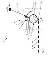
- FIGS. 1 to 4 show different selector lever assemblies in a side view and in a highly schematic representation sketching the underlying principle.
- the illustrated in Figures 1 to 4 different four selector lever assemblies 1 for a not shown here automatic transmission of a motor vehicle not shown each have a pivotable about a pivot axis a selector lever 2 for generating a selection movement w, connecting means 3 for forwarding the selection movement to the automatic transmission and a connection arrangement 4 for transmitting the selection movement w from the selector lever 2 to the connecting means 3.
- the connection assembly 4 is provided with a planetary gear 5, wherein the selector lever 2 with the drive side of the planetary gear 5 and the connecting means 3 are connected to the output side of the planetary gear 5.
- the planetary gear 5 have gear elements in the form of a ring gear 6 with an internal toothing, a planetary gear 7, which is rotatably mounted on a planetary carrier 8 shown here, and a sun gear 9 on.
- the planet carrier 8 is connected to a here reproduced only in symbol form base 10, wherein the base 10 may be, for example, the gear housing of the planetary gear.
- the axis of rotation b of the sun gear 9 and the ring gear 6 coincide with the pivot axis a of the selector lever 2, wherein the pivot axis a and axes of rotation b are perpendicular to the plane of the drawing in the drawing.
- the required size of the respective gear segment is dependent on the size of the pivotal movement w of the selector lever 2. That is, pivotal movement w and respective gear segment must correspond to at least a same circle center angle.
- the circle center point angle of the respective gear segment or the gear segments should be at least slightly larger than that of the pivoting movement w of the selector lever 2.
- the connecting means 3 engage in all four embodiments of the selector lever assembly 1, with respect to the pivot axis a of the selector lever 2, on the side facing away from the selector lever 2 of the planetary gear 5, ie in the approximately reproduced in Figures 1 to 4 mounting position of the planetary gear 5 at the bottom of Planetary gear 5 on.
- the selector lever 2 in its pivoting movement about the pivot axis a on a maximum path component in the longitudinal extension of the connecting means 3, so that a maximum transfer of the selection movement w is ensured on the connecting means 3.
- the connecting means 3 here have a Bowden cable 12, whose pull wire 11 on the underside of the output-side gear element 9 planetary gear 5, the sun gear 9 or the ring gear 6, attacks.
- the Bowden cable 12 an outer tube and the like, in which the puller wire 13 is slidably mounted, wherein the hose is fixed relative to the base 10 and the puller wire 13 with its illustrated here, projecting beyond the hose end can be wound on the sun gear 9.
- the sun gear has a not shown here, at least teilumflindliche groove into which the puller wire is wound into it.
- the puller wire 13 is connected via a fastening means 14 with the sun gear 9 and the ring gear 6 and about a Switzerlanddrahtschwenkachse c, which runs parallel to the pivot axes a and the axis of rotation b, pivotally mounted.
- a first embodiment of the selector lever assembly 1 is shown schematically in a side view.
- the ring gear 6 as the drive side of the planetary gear 5 rotatably connected to the selector lever 2, while the sun gear 9 is positively connected as output side of the planetary gear 5 and / or non-positively connected to the connecting means 3.
- the selector lever 2 engages directly on the outside of the ring gear 6, so that the pivot axis a of the selector lever 2 and the rotation axis b of the ring gear 6 are identical, which is indicated in the figure by the dashed line leading to the center of the ring gear 6.
- the outline drawn in both Figures 1 and 2 about the planetary gear 5 is intended to symbolize a reduced installation space 11 for the planetary gear 5, in which the planetary gear 5 should be installable.
- the ring gear 6 is formed here as a gear segment.
- a second embodiment of the selector lever assembly 1 in which the sun gear 9 is rotatably connected to the selector lever 2 as the drive side of the planetary gear 5, while the ring gear 6 as the output side of the planetary gear 5 form and / or non-positively with the connecting means connected is.
- the ring gear 6 is formed as a gear segment, which is arranged to reduce the maximum height of the planetary gear 5, in installation position laterally to the sun gear 9.
- extension elements 15 are provided, which extend from the gear segment of the ring gear 6 to the side facing away from the selector lever 2 side of the planetary gear 5, ie to the installation position in the lower side of the planetary gear 5, as well as to a radially further inward point.
- a third embodiment of the selector lever assembly 1 is shown.
- ring gear 6 and sun gear 9 are formed as gear segments, the sun gear 9 is rotatably connected to the selector lever 2 as the drive side of the planetary gear 5, while the ring gear 6 is connected as a driven side of the planetary gear 5 positively and / or non-positively connected to the connecting means 3.
- the two gear segments are arranged on the underside of the planetary gear 5, so that the connecting means 3 can attack directly below the planetary gear 7. Due to the design of both transmission elements, the ring gear 6 and the sun gear 9, a further reduction of the size of the planetary gear 5 is possible.
- Fig. 4 shows a fourth embodiment of the selector lever assembly 1 again, in which, as in the third embodiment of the selector lever assembly 1, ring gear 6 and sun gear 9 are formed as gear segments.
- the ring gear 6 is rotatably connected to the selector lever 2 as the drive side of the planetary gear 5, while the sun gear 9 as a driven side of the planetary gear 5 is positively and / or non-positively connected to the connecting means 3.
- extension elements 15 are additionally provided which extend further to the underside of the planetary gear 5 in order to set a desired lever between the pivot axis a or axis of rotation b and the engagement region of the connecting means 3.
Landscapes
- Engineering & Computer Science (AREA)
- General Engineering & Computer Science (AREA)
- Mechanical Engineering (AREA)
- Gear-Shifting Mechanisms (AREA)
- Structure Of Transmissions (AREA)
Priority Applications (3)
| Application Number | Priority Date | Filing Date | Title |
|---|---|---|---|
| EP05100039A EP1679455B1 (fr) | 2005-01-05 | 2005-01-05 | Agencement d'un levier de commande pour une transmission automatique |
| DE502005011121T DE502005011121D1 (de) | 2005-01-05 | 2005-01-05 | Wählhebelanordnung für ein Automatikgetriebe |
| US11/326,308 US7494441B2 (en) | 2005-01-05 | 2006-01-05 | Automatic transmission shift lever assembly |
Applications Claiming Priority (1)
| Application Number | Priority Date | Filing Date | Title |
|---|---|---|---|
| EP05100039A EP1679455B1 (fr) | 2005-01-05 | 2005-01-05 | Agencement d'un levier de commande pour une transmission automatique |
Publications (2)
| Publication Number | Publication Date |
|---|---|
| EP1679455A1 true EP1679455A1 (fr) | 2006-07-12 |
| EP1679455B1 EP1679455B1 (fr) | 2011-03-16 |
Family
ID=34938481
Family Applications (1)
| Application Number | Title | Priority Date | Filing Date |
|---|---|---|---|
| EP05100039A Expired - Lifetime EP1679455B1 (fr) | 2005-01-05 | 2005-01-05 | Agencement d'un levier de commande pour une transmission automatique |
Country Status (3)
| Country | Link |
|---|---|
| US (1) | US7494441B2 (fr) |
| EP (1) | EP1679455B1 (fr) |
| DE (1) | DE502005011121D1 (fr) |
Families Citing this family (3)
| Publication number | Priority date | Publication date | Assignee | Title |
|---|---|---|---|---|
| US9222577B2 (en) * | 2013-09-10 | 2015-12-29 | Gm Global Technology Operations, Llc | Shift linkage assembly for transmission |
| US9976592B2 (en) | 2015-08-27 | 2018-05-22 | Ford Global Technologies, Llc | Automatic transmission shift cable clip |
| DE102024117590B3 (de) | 2024-06-21 | 2025-08-14 | Dr. Ing. H.C. F. Porsche Aktiengesellschaft | Bedienvorrichtung eines Kraftfahrzeugs und Kraftfahrzeug |
Citations (2)
| Publication number | Priority date | Publication date | Assignee | Title |
|---|---|---|---|---|
| US4898045A (en) * | 1987-11-20 | 1990-02-06 | Nippon Cable System Inc. | Control device for boat engine |
| EP0447086A1 (fr) | 1990-03-15 | 1991-09-18 | Massey Ferguson S.A. | Mécanisme sélecteur de rapport de transmission |
Family Cites Families (5)
| Publication number | Priority date | Publication date | Assignee | Title |
|---|---|---|---|---|
| US2522694A (en) * | 1947-04-19 | 1950-09-19 | Alvin R Vogel | Steering system |
| US3363480A (en) * | 1965-10-23 | 1968-01-16 | Bendix Corp | Automatic throttle control mechanism |
| SE403747B (sv) * | 1974-07-26 | 1978-09-04 | Nippon Cable System Inc | Reglermekanism for gemensam reglering av koppling och strypspjell |
| DE4305015C1 (de) * | 1993-02-18 | 1994-03-10 | Ford Werke Ag | Wählhebelanordnung für ein automatisches Getriebe eines Kraftfahrzeuges |
| DE59601125D1 (de) * | 1995-04-08 | 1999-02-25 | Ford Global Tech Inc | Wählhebelanordnung für automatische Getriebe für Kraftfahrzeuge mit manueller Schaltmöglichkeit |
-
2005
- 2005-01-05 DE DE502005011121T patent/DE502005011121D1/de not_active Expired - Lifetime
- 2005-01-05 EP EP05100039A patent/EP1679455B1/fr not_active Expired - Lifetime
-
2006
- 2006-01-05 US US11/326,308 patent/US7494441B2/en not_active Expired - Fee Related
Patent Citations (2)
| Publication number | Priority date | Publication date | Assignee | Title |
|---|---|---|---|---|
| US4898045A (en) * | 1987-11-20 | 1990-02-06 | Nippon Cable System Inc. | Control device for boat engine |
| EP0447086A1 (fr) | 1990-03-15 | 1991-09-18 | Massey Ferguson S.A. | Mécanisme sélecteur de rapport de transmission |
Also Published As
| Publication number | Publication date |
|---|---|
| EP1679455B1 (fr) | 2011-03-16 |
| US20060219041A1 (en) | 2006-10-05 |
| DE502005011121D1 (de) | 2011-04-28 |
| US7494441B2 (en) | 2009-02-24 |
Similar Documents
| Publication | Publication Date | Title |
|---|---|---|
| DE102014201254B4 (de) | Getriebeanordnung und Antriebsstrang für ein Hybridfahrzeug sowie Hybridfahrzeug | |
| EP0683875B1 (fr) | Transmission hydrostatique variable a division de puissance | |
| EP2773885B1 (fr) | Boîte de vitesses avec commande sous charge | |
| DE10046589B4 (de) | Stellvorrichtung für ein einstellbares Getriebe, insbesondere für die Bereichsvorwahl eines Automatikgetriebes | |
| DE3917579C2 (de) | Automatikgetriebe für Kraftfahrzeuge | |
| DE112004002276T5 (de) | Zusammengesetztes Planetengetriebe und Getriebezüge | |
| DE10333112A1 (de) | Kraftfahrzeug-Antriebssystem | |
| DE102019131764A1 (de) | Antriebsvorrichtung für ein Kraftfahrzeug | |
| DE19910576B4 (de) | Parksperre für ein Schaltgetriebe | |
| DE2127826A1 (de) | Mechanismus für das Steuern eines quer anzuordnenden Motor-Triebwerks mit automatischem Getriebe | |
| EP4077980B1 (fr) | Ensemble tambour de changement de vitesse pour un dispositif de changement de vitesse d'une unité de transmission et procédé de changement de vitesse | |
| WO2017032596A1 (fr) | Dispositif de réglage pour siège de véhicule | |
| DE60317975T2 (de) | Stufenloses Getriebe für Kraftfahrzeuge, insbesondere für landwirtschaftliche Traktoren | |
| DE102012216231B3 (de) | Planetengetriebe mit einer Kupplungseinrichtung sowie Getriebeeinrichtung für ein Fahrzeug mit dem Planetengetriebe | |
| EP1679455B1 (fr) | Agencement d'un levier de commande pour une transmission automatique | |
| DE102019201636B4 (de) | Getriebeeinrichtung für ein Kraftfahrzeug mit einem Stufenplanetengetriebe | |
| DE102004003691B4 (de) | Kegelringgetriebe | |
| DE19654695B4 (de) | Stufenloses Getriebe | |
| EP0299156A2 (fr) | Dispositif pour commander le mouvement de coulisser et de lever du couvercle de toits levants et coulissants | |
| WO2021013301A1 (fr) | Dispositif d'entraînement pour un véhicule à moteur comprenant au choix un porte-satellite commutable solidaire du boîtier ou une couronne | |
| DE10347273B4 (de) | Parallelstranggetriebe für ein Kraftfahrzeug und Verfahren zum Betreiben | |
| DE19938934A1 (de) | Getriebe | |
| DE102019211734A1 (de) | Antriebsvorrichtung zum Verstellen einer Fahrzeugbaugruppe | |
| DE69507259T2 (de) | Automatisches Getriebe für ein Kraftfahrzeug | |
| WO2024038083A1 (fr) | Agencement d'entraînement pour le réglage motorisé d'un élément fonctionnel d'un agencement de verrouillage de véhicule automobile dans le cadre d'un processus de réglage |
Legal Events
| Date | Code | Title | Description |
|---|---|---|---|
| PUAI | Public reference made under article 153(3) epc to a published international application that has entered the european phase |
Free format text: ORIGINAL CODE: 0009012 |
|
| AK | Designated contracting states |
Kind code of ref document: A1 Designated state(s): AT BE BG CH CY CZ DE DK EE ES FI FR GB GR HU IE IS IT LI LT LU MC NL PL PT RO SE SI SK TR |
|
| AX | Request for extension of the european patent |
Extension state: AL BA HR LV MK YU |
|
| 17P | Request for examination filed |
Effective date: 20070112 |
|
| AKX | Designation fees paid |
Designated state(s): DE FR GB |
|
| 17Q | First examination report despatched |
Effective date: 20070226 |
|
| GRAP | Despatch of communication of intention to grant a patent |
Free format text: ORIGINAL CODE: EPIDOSNIGR1 |
|
| GRAS | Grant fee paid |
Free format text: ORIGINAL CODE: EPIDOSNIGR3 |
|
| GRAA | (expected) grant |
Free format text: ORIGINAL CODE: 0009210 |
|
| RAP1 | Party data changed (applicant data changed or rights of an application transferred) |
Owner name: FORD GLOBAL TECHNOLOGIES, LLC, A SUBSIDARY OF FORD |
|
| AK | Designated contracting states |
Kind code of ref document: B1 Designated state(s): DE FR GB |
|
| REG | Reference to a national code |
Ref country code: GB Ref legal event code: FG4D Free format text: NOT ENGLISH |
|
| REF | Corresponds to: |
Ref document number: 502005011121 Country of ref document: DE Date of ref document: 20110428 Kind code of ref document: P |
|
| REG | Reference to a national code |
Ref country code: DE Ref legal event code: R096 Ref document number: 502005011121 Country of ref document: DE Effective date: 20110428 |
|
| PLBE | No opposition filed within time limit |
Free format text: ORIGINAL CODE: 0009261 |
|
| STAA | Information on the status of an ep patent application or granted ep patent |
Free format text: STATUS: NO OPPOSITION FILED WITHIN TIME LIMIT |
|
| 26N | No opposition filed |
Effective date: 20111219 |
|
| REG | Reference to a national code |
Ref country code: DE Ref legal event code: R097 Ref document number: 502005011121 Country of ref document: DE Effective date: 20111219 |
|
| PGFP | Annual fee paid to national office [announced via postgrant information from national office to epo] |
Ref country code: GB Payment date: 20121228 Year of fee payment: 9 |
|
| PGFP | Annual fee paid to national office [announced via postgrant information from national office to epo] |
Ref country code: DE Payment date: 20130131 Year of fee payment: 9 Ref country code: FR Payment date: 20130128 Year of fee payment: 9 |
|
| REG | Reference to a national code |
Ref country code: DE Ref legal event code: R119 Ref document number: 502005011121 Country of ref document: DE |
|
| GBPC | Gb: european patent ceased through non-payment of renewal fee |
Effective date: 20140105 |
|
| REG | Reference to a national code |
Ref country code: DE Ref legal event code: R119 Ref document number: 502005011121 Country of ref document: DE Effective date: 20140801 |
|
| PG25 | Lapsed in a contracting state [announced via postgrant information from national office to epo] |
Ref country code: DE Free format text: LAPSE BECAUSE OF NON-PAYMENT OF DUE FEES Effective date: 20140801 |
|
| REG | Reference to a national code |
Ref country code: FR Ref legal event code: ST Effective date: 20140930 |
|
| PG25 | Lapsed in a contracting state [announced via postgrant information from national office to epo] |
Ref country code: GB Free format text: LAPSE BECAUSE OF NON-PAYMENT OF DUE FEES Effective date: 20140105 Ref country code: FR Free format text: LAPSE BECAUSE OF NON-PAYMENT OF DUE FEES Effective date: 20140131 |