EP1679510B1 - Procede et dispositif d'analyse d'echantillons - Google Patents
Procede et dispositif d'analyse d'echantillons Download PDFInfo
- Publication number
- EP1679510B1 EP1679510B1 EP04792584A EP04792584A EP1679510B1 EP 1679510 B1 EP1679510 B1 EP 1679510B1 EP 04792584 A EP04792584 A EP 04792584A EP 04792584 A EP04792584 A EP 04792584A EP 1679510 B1 EP1679510 B1 EP 1679510B1
- Authority
- EP
- European Patent Office
- Prior art keywords
- electrochemical biosensor
- output
- integration circuit
- double integration
- sample
- Prior art date
- Legal status (The legal status is an assumption and is not a legal conclusion. Google has not performed a legal analysis and makes no representation as to the accuracy of the status listed.)
- Expired - Lifetime
Links
- 238000004458 analytical method Methods 0.000 title claims description 13
- 230000010354 integration Effects 0.000 claims description 50
- 239000003990 capacitor Substances 0.000 claims description 45
- 239000008280 blood Substances 0.000 claims description 40
- 210000004369 blood Anatomy 0.000 claims description 40
- 238000005070 sampling Methods 0.000 claims description 36
- 238000000034 method Methods 0.000 claims description 16
- 239000003153 chemical reaction reagent Substances 0.000 claims description 10
- 238000012284 sample analysis method Methods 0.000 claims description 9
- 238000007599 discharging Methods 0.000 claims description 4
- 230000027756 respiratory electron transport chain Effects 0.000 claims description 3
- 230000001737 promoting effect Effects 0.000 claims description 2
- 230000004044 response Effects 0.000 description 68
- WQZGKKKJIJFFOK-GASJEMHNSA-N Glucose Natural products OC[C@H]1OC(O)[C@H](O)[C@@H](O)[C@@H]1O WQZGKKKJIJFFOK-GASJEMHNSA-N 0.000 description 27
- 239000008103 glucose Substances 0.000 description 27
- 238000005259 measurement Methods 0.000 description 18
- 230000036770 blood supply Effects 0.000 description 12
- 238000012790 confirmation Methods 0.000 description 11
- 230000006870 function Effects 0.000 description 5
- 230000008569 process Effects 0.000 description 5
- HVYWMOMLDIMFJA-DPAQBDIFSA-N cholesterol Chemical compound C1C=C2C[C@@H](O)CC[C@]2(C)[C@@H]2[C@@H]1[C@@H]1CC[C@H]([C@H](C)CCCC(C)C)[C@@]1(C)CC2 HVYWMOMLDIMFJA-DPAQBDIFSA-N 0.000 description 4
- JVTAAEKCZFNVCJ-UHFFFAOYSA-N lactic acid Chemical compound CC(O)C(O)=O JVTAAEKCZFNVCJ-UHFFFAOYSA-N 0.000 description 4
- 108090000854 Oxidoreductases Proteins 0.000 description 3
- 102000004316 Oxidoreductases Human genes 0.000 description 3
- 230000008859 change Effects 0.000 description 3
- 210000002700 urine Anatomy 0.000 description 3
- 230000009471 action Effects 0.000 description 2
- 238000011088 calibration curve Methods 0.000 description 2
- 235000012000 cholesterol Nutrition 0.000 description 2
- 238000001514 detection method Methods 0.000 description 2
- 235000014655 lactic acid Nutrition 0.000 description 2
- 239000004310 lactic acid Substances 0.000 description 2
- 239000007788 liquid Substances 0.000 description 2
- 239000007791 liquid phase Substances 0.000 description 2
- 210000003296 saliva Anatomy 0.000 description 2
- 239000000758 substrate Substances 0.000 description 2
- 108010050375 Glucose 1-Dehydrogenase Proteins 0.000 description 1
- 108010015776 Glucose oxidase Proteins 0.000 description 1
- 239000004366 Glucose oxidase Substances 0.000 description 1
- WQZGKKKJIJFFOK-VFUOTHLCSA-N beta-D-glucose Chemical compound OC[C@H]1O[C@@H](O)[C@H](O)[C@@H](O)[C@@H]1O WQZGKKKJIJFFOK-VFUOTHLCSA-N 0.000 description 1
- 238000002848 electrochemical method Methods 0.000 description 1
- 235000001727 glucose Nutrition 0.000 description 1
- 235000019420 glucose oxidase Nutrition 0.000 description 1
- 229940116332 glucose oxidase Drugs 0.000 description 1
- 238000000691 measurement method Methods 0.000 description 1
- -1 potassium ferricyanide Chemical compound 0.000 description 1
- 239000007787 solid Substances 0.000 description 1
- 125000006850 spacer group Chemical group 0.000 description 1
Images


Classifications
-
- G—PHYSICS
- G01—MEASURING; TESTING
- G01N—INVESTIGATING OR ANALYSING MATERIALS BY DETERMINING THEIR CHEMICAL OR PHYSICAL PROPERTIES
- G01N27/00—Investigating or analysing materials by the use of electric, electrochemical, or magnetic means
- G01N27/26—Investigating or analysing materials by the use of electric, electrochemical, or magnetic means by investigating electrochemical variables; by using electrolysis or electrophoresis
- G01N27/416—Systems
-
- G—PHYSICS
- G01—MEASURING; TESTING
- G01N—INVESTIGATING OR ANALYSING MATERIALS BY DETERMINING THEIR CHEMICAL OR PHYSICAL PROPERTIES
- G01N27/00—Investigating or analysing materials by the use of electric, electrochemical, or magnetic means
- G01N27/26—Investigating or analysing materials by the use of electric, electrochemical, or magnetic means by investigating electrochemical variables; by using electrolysis or electrophoresis
- G01N27/28—Electrolytic cell components
- G01N27/30—Electrodes, e.g. test electrodes; Half-cells
- G01N27/327—Biochemical electrodes, e.g. electrical or mechanical details for in vitro measurements
- G01N27/3271—Amperometric enzyme electrodes for analytes in body fluids, e.g. glucose in blood
- G01N27/3273—Devices therefor, e.g. test element readers, circuitry
-
- G—PHYSICS
- G01—MEASURING; TESTING
- G01N—INVESTIGATING OR ANALYSING MATERIALS BY DETERMINING THEIR CHEMICAL OR PHYSICAL PROPERTIES
- G01N27/00—Investigating or analysing materials by the use of electric, electrochemical, or magnetic means
- G01N27/26—Investigating or analysing materials by the use of electric, electrochemical, or magnetic means by investigating electrochemical variables; by using electrolysis or electrophoresis
- G01N27/28—Electrolytic cell components
-
- Y—GENERAL TAGGING OF NEW TECHNOLOGICAL DEVELOPMENTS; GENERAL TAGGING OF CROSS-SECTIONAL TECHNOLOGIES SPANNING OVER SEVERAL SECTIONS OF THE IPC; TECHNICAL SUBJECTS COVERED BY FORMER USPC CROSS-REFERENCE ART COLLECTIONS [XRACs] AND DIGESTS
- Y10—TECHNICAL SUBJECTS COVERED BY FORMER USPC
- Y10T—TECHNICAL SUBJECTS COVERED BY FORMER US CLASSIFICATION
- Y10T436/00—Chemistry: analytical and immunological testing
- Y10T436/11—Automated chemical analysis
- Y10T436/112499—Automated chemical analysis with sample on test slide
-
- Y—GENERAL TAGGING OF NEW TECHNOLOGICAL DEVELOPMENTS; GENERAL TAGGING OF CROSS-SECTIONAL TECHNOLOGIES SPANNING OVER SEVERAL SECTIONS OF THE IPC; TECHNICAL SUBJECTS COVERED BY FORMER USPC CROSS-REFERENCE ART COLLECTIONS [XRACs] AND DIGESTS
- Y10—TECHNICAL SUBJECTS COVERED BY FORMER USPC
- Y10T—TECHNICAL SUBJECTS COVERED BY FORMER US CLASSIFICATION
- Y10T436/00—Chemistry: analytical and immunological testing
- Y10T436/11—Automated chemical analysis
- Y10T436/115831—Condition or time responsive
-
- Y—GENERAL TAGGING OF NEW TECHNOLOGICAL DEVELOPMENTS; GENERAL TAGGING OF CROSS-SECTIONAL TECHNOLOGIES SPANNING OVER SEVERAL SECTIONS OF THE IPC; TECHNICAL SUBJECTS COVERED BY FORMER USPC CROSS-REFERENCE ART COLLECTIONS [XRACs] AND DIGESTS
- Y10—TECHNICAL SUBJECTS COVERED BY FORMER USPC
- Y10T—TECHNICAL SUBJECTS COVERED BY FORMER US CLASSIFICATION
- Y10T436/00—Chemistry: analytical and immunological testing
- Y10T436/12—Condition responsive control
-
- Y—GENERAL TAGGING OF NEW TECHNOLOGICAL DEVELOPMENTS; GENERAL TAGGING OF CROSS-SECTIONAL TECHNOLOGIES SPANNING OVER SEVERAL SECTIONS OF THE IPC; TECHNICAL SUBJECTS COVERED BY FORMER USPC CROSS-REFERENCE ART COLLECTIONS [XRACs] AND DIGESTS
- Y10—TECHNICAL SUBJECTS COVERED BY FORMER USPC
- Y10T—TECHNICAL SUBJECTS COVERED BY FORMER US CLASSIFICATION
- Y10T436/00—Chemistry: analytical and immunological testing
- Y10T436/14—Heterocyclic carbon compound [i.e., O, S, N, Se, Te, as only ring hetero atom]
- Y10T436/142222—Hetero-O [e.g., ascorbic acid, etc.]
- Y10T436/143333—Saccharide [e.g., DNA, etc.]
- Y10T436/144444—Glucose
Definitions
- the present invention relates to a technique for analyzing a particular component (e.g. glucose, cholesterol or lactic acid) in a sample (biochemical sample such as blood or urine).
- a particular component e.g. glucose, cholesterol or lactic acid
- a sample biological sample such as blood or urine
- the glucose sensor maybe designed to output the response current, which is necessary for computing the blood glucose level, when it is mounted to an analytical apparatus.
- the magnitude of the response current is determined by utilizing a double integration circuit including a capacitor, and the blood glucose level is computed based on the determined response current.
- the magnitude of the response current is determined based on the discharge time (T 2 ) of the capacitor after the capacitor is charged with the electric charge related with the response current for a predetermined time period (T 1 ).
- T 2 discharge time
- T 1 the determination of the response current
- the determination of the response current is performed at predetermined time intervals (t).
- the response current (I 1 ) for computing the blood glucose level is sampled at the time
- the charge time (T 1 ) of the capacitor it is preferable to set the charge time (T 1 ) of the capacitor relatively long. Therefore, for the measurement accuracy of the response current, the time interval (t) for measuring the response current need be set relatively long.
- An obj ect of the present invention is to enhance the accuracy of sample analysis by accurately finding the time when the sample is supplied to the analytical tool and the output from the analytical tool to be used for the computation.
- a sample analysis method comprising: a first step of confirming that a sample is supplied to an electrochemical biosensor based on output from the electrochemical biosensor; a second step of grasping a level of the output from the electrochemical biosensor at least once after the supply of the sample to the electrochemical biosensor is confirmed; and a third step of performing computation necessary for the analysis of the sample; characterized that the grasping of the output from the electrochemical biosensor in the first step and the second step is performed based on output from a double integration circuit which is obtained by inputting the output from the electrochemical biosensor into the double integration circuit; wherein the first step comprises grasping a level of the output from the double integration circuit repetitively at a first sampling interval in which the inputting into the double integration circuit is started and the outputting from the double integration circuit is finished; and wherein, in grasping a level of the output from the double integration circuit in the second step, a second sampling interval in which the inputting into the double integration circuit is started and the outputting
- the output from the electrochemical biosensor is grasped by performing the inputting of the output from the electrochemical biosensor into the double integration circuit and the outputting from the double integration circuit repetitively at the second sampling interval.
- the first sampling interval is selected from the range of 10 to 30 msec, whereas the second sampling interval is selected from the range of 30 to 300 msec.
- the double integration circuit to be used includes a capacitor for storing the output from the electrochemical biosensor as electric charge and then discharging the stored electric charge and is capable of grasping the output from the electrochemical biosensor based on the discharge time of the capacitor.
- the charge time of the capacitor in the first sampling interval in the first step is shorter than charge time of the capacitor in the second sampling interval in the second step.
- the charge time of the capacitor in the first sampling interval in the first step is selected from the range of 5 to 15 msec
- the charge time of the capacitor in the second sampling interval in the second step is selected from the range of 15 to 150 msec.
- the electrochemical biosensor to be used includes an electrode for outputting electric physical quantity.
- the electrochemical biosensor to be used includes a reagent portion containing at least one reagent for promoting the electron transfer between the particular component and the electrode, and an additional electrode for applying, together with the electrode, voltage to a coexistence system of the sample and the at least one reagent.
- the electric physical quantity is outputted from the electrode as a current by applying voltage to the coexistence system using the electrode and the additional electrode.
- the electrochemical biosensor to be used is designed to use e.g. blood as the sample.
- the present invention is also applicable to the use of an electrochemical biosensor designed to use a sample other than blood, i.e., urine or saliva, for example.
- a sample analysis apparatus to be used with an electrochemical biosensor mounted thereto for analyzing a sample supplied to the electrochemical biosensor based on output from the electrochemical biosensor, the apparatus comprising: a double integration circuit into which the output from the electrochemical biosensor is inputted and which outputs a physical quantity related to the input; and a controller for controlling timing at which the output from the electrochemical biosensor is inputted into the double integration circuit and timing at which the physical quantity is outputted from the double integration circuit; characterized that the controller is adapted to perform the steps of the method according to claim 1 so that a sampling interval in which the inputting into the double integration circuit is started and the outputting from the double integration circuit is finished becomes longer in a state after the supply of the sample to the electrochemical biosensor is confirmed than in a state before the supply of the sample to the electrochemical biosensor is confirmed.
- the double integration circuit includes a capacitor for storing the output from the electrochemical biosensor as electric charge and then discharging the stored electric charge and is capable of grasping the output from the electrochemical biosensor based on the discharge time of the capacitor.
- the controller performs control so that the charge time of the capacitor becomes longer in the state after the supply of the sample to the electrochemical biosensor is confirmed than in the state before the supply of the sample to the electrochemical biosensor is confirmed.
- the sample analysis apparatus of the present invention further comprises a switch for selecting the state in which the double integration circuit is directly or indirectly connected to ground or the state in which the double integration circuit is connected to the electrode.
- the controller controls the switch to control the timing at which the output from the electrochemical biosensor is inputted into the double integration circuit and the timing at which the physical quantity is outputted from the double integration circuit.
- the state in which the double integration circuit is indirectly connected to ground means the state in which a reference supply intervenes between the double integration circuit and the ground.
- the analytical apparatus 1 which is used with a biosensor 2 mounted thereto, includes a current/voltage converting circuit 10, an A/D converter 11, a circuit power source 12, a comparator 13, a clockpulse oscillator 14, a counter 15 and a control circuit 16.
- the biosensor 2 used in the analytical apparatus 1 functions to analyze a particular component contained in a sample (e.g. blood) by an electrochemical method and is designed to be disposable. As shown in Figs. 2 through 4 , the biosensor 2 comprises a substrate 20 and a cover 22 stacked thereon via a spacer 21 formed with a slit 21a.
- the above-described elements 20-22 define a flow path 23.
- the flow path 23 is provided for moving the sample introduced through a sample introduction port 23a toward a hole 22a of the cover 22 by utilizing capillary action and for providing a reaction field for the sample and a reagent.
- the substrate 20 is formed with a working electrode 20A and a counter electrode 20B for applying a voltage to the reaction filed.
- the working electrode 20A and the counter electrode 20B have respective first ends 20Aa and 20Ba which are connected to each other by a reagent portion 24.
- the working electrode 20A and the counter electrode 20B have respective second ends 20Ab and 20Bb which are brought into contact with a first and a second terminals 17a and 17b of the analytical apparatus 1 when the biosensor 2 is mounted to the analytical apparatus 1.
- the reagent portion 24 is in a solid state including an oxidoreductase and an electron mediator and is soluble when the sample is supplied thereto.
- the kinds of oxidoreductase and electron mediator are selected depending on e.g. the kind of the component (particular component) to be measured.
- the component particular component
- glucose dehydrogenase or glucose oxidase is used as the oxidoreductase
- potassium ferricyanide is used as the electron mediator.
- the current/voltage converting circuit 10 shown in Fig. 1 functions to convert information obtained from the biosensor 2 as a current value into a voltage value for inputting into the A/D converter 11.
- the A/D converter 11 functions to convert the inputted analog value to a digital value for outputting and is structured as a double integration circuit.
- the A/D converter 11 comprises a capacitor 11A and an operational amplifier 11B which includes an inverting input 11Ba and a non-inverting input 11Bb.
- the operational amplifier 11B is connectable to terminals 18A, 18b via a switch S. Therefore, in the operational amplifier 11B, by selectively connecting the switch S to the terminal 18A or the terminal 18B, the inverting input 11Ba is selectively connected to the current/voltage converting circuit 10 or ground.
- the non-inverting input 11Bb is connected to a first reference supply 11C.
- the capacitor 11A is charged when connected to the current/voltage converting circuit 10 and discharged when connected to the first reference supply 11C.
- the output 11Bc of the A/D converter 11 is connected to a non-inverting input 13a of the comparator 13, which will be described later.
- the discharge from the capacitor 11A (the potential difference at the capacitor 11A), i.e., the output related with the output from the biosensor 2 is inputted.
- the circuit power source 12 functions to apply a voltage to the biosensor 2 and supply power to electronic components.
- a DC power source such as a dry cell.
- the comparator 13 is provided to grasp the output from the A/D converter 11 (operational amplifier 11B), i.e., the output of the biosensor 2.
- the non-inverting input 13a of the comparator 13 is connected to the A/D converter 11 (operational amplifier 11B), whereas the inverting input 13b is connected to a second reference supply 13C.
- the comparator 13 determines whether or not the output from the A/D converter 11 (operational amplifier 11B) is greater than the power supply voltage of the second reference supply 13C.
- the comparator 13 outputs the signal "1".
- the comparator outputs the signal "0".
- the clockpulse oscillator 14 generates a clockpulse signal to be supplied to the counter 15 at a predetermined period.
- the counter 15 counts the number of clockpulse signals from particular reference time.
- the control circuit 16 which serves to control various elements, comprises a CPU, a ROM and a RAM, for example. For instance, the control circuit 16 checks and resets the number of clockpulse signals at the counter 15, changes the state of the switch S or computes the concentration of a particular component contained in a sample.
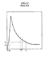
- Fig. 5 shows an example of change with time of the output (response current) from the biosensor 2.
- concentration of a particular component is computed at the control circuit 16 based on the response current outputted from the biosensor 2 at the time (t 1 ) after a predetermined time period T has elapsed from the time (to) at which the supply of the sample to the biosensor 2 was confirmed.
- the control circuit 16 grasps the response current as a voltage value.
- the timing at which the voltage value is to be measured is controlled by the control circuit 16.
- the supply of the sample is confirmed by sampling the response current at predetermined intervals of time (T 1 ) and determining whether or not the response current exceeds a threshold.
- Each interval of time (T 1 ) for sampling the response current may be set to 10 to 30 msec, for example.
- the switch S is first connected to the terminal 18A, as indicated by a solid line in Fig. 1 , to connect the A/D converter 11 to the biosensor 2.
- the output (electric charge) from the biosensor 2 is stored in the capacitor 11A for a predetermined time period (charge time) (T 1a ).
- the charge time (T 1a ) may be set to 5 to 15 msec, for example.
- the switch S is connected to the terminal 18B to connect the A/D converter 11 to ground, thereby causing the capacitor 11A to discharge.
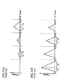
- the control circuit 16 computes, based on the output from the comparator 13, the discharge time (T 1b ) taken for the output from the A/D converter 11 to drop to the power supply voltage of the second reference supply 13C (See Fig. 7A ).
- the discharge time (T 1b ) is proportional to the electric charge stored in the capacitor 11A, i.e., the output from the biosensor 2 in the charge time (T 1a ). Therefore, in the control circuit 16 shown in Fig. 1 , the response current (output from the biosensor 2) is grasped as a voltage (E 1 ) related with the discharge time (T 1b ).
- the control circuit 16 every time the responsive current for computation is grasped as a voltage value (E 1 ), the voltage value (E 1 ) is compared with a threshold (E 10 ). When the grasped voltage value (E 1 ) exceeds the threshold (E 10 ), it is determined that the sample is supplied to the biosensor 2. However, in the case where the output from the A/D converter 11 does not drop to the power supply voltage of the second reference supply 13C even after a predetermined time period has elapsed, it can be judged that the charge of the capacitor 11A is large and the output from the biosensor 2 is high. In such a case, the control circuit 16 may judge, without conducting the comparison with the threshold (E 10 ), that the sample is supplied to the biosensor 2.
- T 2 time
- the time interval (T 2 ) for sampling the response current for the computation is set to 30 to 300 msec, for example, which is longer than the time interval (T 1 ) for grasping the response current for the confirmation of sample supply.
- the charge time (T 2a ) for storing the output (electric charge) from the biosensor 2 in the capacitor 11A is set to 15 to 150 msec, which is also longer than the charge time (T 1a ) for grasping the response current for the sample supply confirmation.
- settling time (T 2c ) is provided as the preceding stage of charging the capacitor 11A to sufficiently stabilize the charge amount of the capacitor 11A before charging the capacitor 11A.
- the discharge time (T 2b ) is proportional to the electric charge stored in the capacitor 11A, i.e., the output from the biosensor 2 in the charge time (T 2a ). Therefore, in the control circuit 16 shown in Fig. 1 , the response current (output from the biosensor 2) is grasped from the discharge time (T 1b ) as a voltage (E 2 ).
- the concentration of a particular component in the sample is computed in the control circuit 16 by applying the voltage value (E 2 ) to an analytical curve prepared in advance.
- the calibration curve is prepared as a function or a measurement table showing the relationship between voltage value (E2) and concentration of the particular component and stored in a memory in the control circuit 16.
- the user mounts the biosensor 2 to the analytical apparatus 1 and introduces blood into the flow path 23 through the sample introduction port 23a of the biosensor 2 (See Fig. 3 ).
- the blood travels toward the hole 22a by capillary action.
- the control circuit 16 determines whether or not the biosensor 2 is mounted. Specifically, a detection sensor such as a pressure sensitive sensor or a photo sensor may be provided at a portion in the analytical apparatus 1 at which the biosensor 2 is to be mounted, and the above-described determination may be made based on the output from the detection sensor. Alternatively, the user may operate a button to make the control circuit to recognize that the biosensor 2 is mounted to the analytical apparatus 1.
- a detection sensor such as a pressure sensitive sensor or a photo sensor may be provided at a portion in the analytical apparatus 1 at which the biosensor 2 is to be mounted, and the above-described determination may be made based on the output from the detection sensor.
- the user may operate a button to make the control circuit to recognize that the biosensor 2 is mounted to the analytical apparatus 1.
- the analysis operation is not performed.
- a voltage is applied across the working electrode 20A and the counter electrode 20B of the biosensor 2 (S3) Then, whether or not blood is supplied to the biosensor 2 is checked (S4).
- the voltage application across the working electrode 20A and the counter electrode 20B may be started before the mounting of the biosensor 2 is confirmed in the analytical apparatus 1, i.e., from the time when the biosensor 2 is mounted to the analytical apparatus 1.
- the current generated due to the liquid conduction between the working electrode 20A and the counter electrode 20B (see Figs. 3 and 4 ) by the blood is grasped as a voltage value at a plurality of measurement points with predetermined time intervals (T 1 ) as shown in Fig. 5 , and whether or not the voltage value exceeds a predetermined value (threshold) (E 10 ) is checked.
- T 1 predetermined time intervals
- E 10 a predetermined value
- whether or not the blood has reached the working electrode 20A is determined by checking the liquid conduction between the working electrode 20A and the counter electrode 20B.
- the fact that the supply of the blood to the biosensor 2 is confirmed in the control circuit 16 means that the blood has reached at least the working electrode 20A of the biosensor 2.
- the reagent portion 24 (See Figs. 2-4 ) is dissolved to establish a liquid phase reaction system in the flow path 23.
- glucose is oxidized, whereas the electron mediator is reduced.
- the electron mediator is oxidized, and the electrons emitted are supplied to the working electrode 20A and measured as the response current.
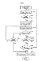
- the response value measurement (S5) is performed following the process steps shown in Fig. 10 .
- the control circuit 16 first resets the count number at the counter 15 and causes the counter 15 to start counting clockpulse signals (S21) and determines whether or not a predetermined time period has elapsed from the start of counting, i.e., whether or not the settling time (T 2c ) (see Fig. 7B ) is finished (S22). The determination is made in the control circuit 16 based on whether or not the count number at the counter 15 has reached the count number corresponding to the settling time (T 2c ).
- control circuit 16 connects the switch S to the terminal 18A (S23). Then, the control circuit resets the count number at the counter 15 and causes the counter 15 to start counting the clockpulse signals (S24).
- the control circuit 16 By connecting the switch S to the terminal 18A, the biosensor 2 is connected to the A/D converter 11, and electric charge is stored in the capacitor 11A of the A/D converter 11 due to the current generated at the biosensor 2 (S25).
- the determination is made by checking whether or not the count number of the clockpulse signals at the counter 15 has reached the count number corresponding to the charge time (T 2a ). The check is repetitively performed until it is determined in the control circuit 16 that the predetermined time period has elapsed, i.e., the charge time (T 2a ) is finished (S26: YES) (S25, S26).
- the control circuit 16 When it is determined in the control circuit 16 that the charge time (T 2a ) is finished (S26: YES), the control circuit 16 connects the switch S to the terminal 18B (S27). Then, after resetting the count number at the counter 15, the control circuit causes the counter 15 to start counting the clockpulse signals (S28). Thus, the non-inverting input 11Ba of the A/D converter is grounded, and the electric charge is discharged from the capacitor 11A (S29).
- the control circuit 16 determines whether or not the output from the A/D converter 11 is not greater than the reference supply value (E ref ) of the second reference supply 13C (S30). Similarly to the blood supply confirmation process (S4), the determination is made by checking, in the control circuit 16, whether the output from the comparator 13 is "1" or "0".
- the control circuit 16 When it is determined that the output from the A/D converter 11 is not no greater than the reference supply value (E ref ) of the second reference supply 13C(S30: NO), the control circuit 16 continues the discharge from the capacitor 11A (S29). The control circuit 16 controls the switch S and so on to repeat the discharge in S29 and the determination in S30 until it is determined in S30 that the output from the A/D converter 11 is not greater than the reference supply value (E ref ) of the second reference supply 13C (S30: YES).
- the response value i.e., the output from the biosensor 2 in the charge time (T 2a ) is computed (S31). Specifically, the discharge time (T 2b ) from the start of the discharge till when the output from the A/D converter 11 drops to the reference supply value (E ref ) of the second reference supply 13C is computed. Based on the discharge time (T 2b ), the response value is computed as a voltage value.
- a determination is made as to whether or not a predetermined time period ( T 2 -(T 2c +T 2a )) (See Fig. 7B ) has elapsed from the start of the discharge of the capacitor 11A, i.e., the sampling time (T 2 ) is finished (S32).
- the response value measurement is completed.
- a determination is made as to whether or not a predetermined time period T (See Fig. 5 ) has elapsed from when the supply of the blood is confirmed in the control circuit 16 (S6). That is, a determination is made as to whether or not the previous response value measurement (S5) corresponds to the sampling to be utilized for computing the blood glucose level.
- the response value measurement (S5) is repetitively performed until it is determined that the predetermined time period T has elapsed (S6: YES).
- the response value obtained in the most recent measurement is employed as the response value for the computation (S7), and the blood glucose level is computed based on that response value.
- the computation of the blood glucose level is performed by applying the response value to a calibration curve.
- the input to the inverting input 11Ba and the input to the non-inverting input 11Bb need be accurately compared with each other in the operational amplifier 11B, and the discharge time (T 1b ), (T 2b ) (See Figs. 7A and 7B ) need be measured accurately.
- the discharge time (T 1b ), (T 2b ) (See Figs. 7A and 7B ) need be measured accurately.
- the charge time (T 1a ), (T 2a ) is short, the measurement accuracy of the response current deteriorates.
- the control circuit 16 (See Fig. 1 ) of the analytical apparatus 1 performs control so that the sampling time (T 1 ) and the charge time (T 1a ) of the capacitor 11A in grasping the response current to confirm the blood supply to the biosensor 2 becomes relatively short.
- the control circuit 16 (See Fig. 1 ) performs control so that the sampling time (T 2 ) and the charge time (T 2a ) of the capacitor 11A become relatively long.
- the difference between the time when the supply of blood to the biosensor 2 is detected and the time when the blood is actually supplied to the biosensor 2 is small. Further, the response value for computing the blood glucose level can be grasped accurately. As a result, variations of the period from when the blood is supplied until the sampling of the response current for the computation can be suppressed, and the blood glucose level can be measured accurately.
- the response value measurement is performed a plurality of times in the period from when the sample supply is confirmed until when the response value for computing the blood glucose level is sampled.
- the response value for computing the blood glucose level is sampled after a predetermined time period has elapsed from the confirmation of the blood supply. In the present invention, however, it is only necessary to conduct the response current measurement at least once when the predetermined time period has elapsed.
- the response value may be measured a plurality of times before the predetermined time period elapses, and the blood glucose level may be computed based on the integration of the plurality of response values.
- the present invention is also applicable to an analytical apparatus for performing the analysis of a component other than glucose (e.g., cholesterol or lactic acid) which is contained in blood or to the analysis of a sample other than blood (such as urine or saliva).
- a component other than glucose e.g., cholesterol or lactic acid
- a sample other than blood such as urine or saliva
Landscapes
- Health & Medical Sciences (AREA)
- Chemical & Material Sciences (AREA)
- Life Sciences & Earth Sciences (AREA)
- Electrochemistry (AREA)
- Molecular Biology (AREA)
- Chemical Kinetics & Catalysis (AREA)
- Physics & Mathematics (AREA)
- Analytical Chemistry (AREA)
- Biochemistry (AREA)
- General Health & Medical Sciences (AREA)
- General Physics & Mathematics (AREA)
- Immunology (AREA)
- Pathology (AREA)
- Hematology (AREA)
- Investigating Or Analysing Biological Materials (AREA)
Claims (11)
- Procédé d'analyse d'échantillon comprenant : une première étape consistant à confirmer qu'un échantillon est fourni à un biocapteur électrochimique (2) sur la base de la sortie du biocapteur électrochimique (2), une deuxième étape consistant à saisir un niveau de la sortie du biocapteur électrochimique (2) au moins une fois après que la fourniture de l'échantillon au biocapteur électrochimique (2) ait été confirmée, et une troisième étape consistant à exécuter un calcul nécessaire à l'analyse de l'échantillon,
caractérisé en ce que la saisie de la sortie du biocapteur électrochimique (2) à la première étape et à la deuxième étape est exécutée sur la base d'une sortie d'un circuit de double intégration (11) qui est obtenue en entrant la sortie du biocapteur électrochimique (2) dans le circuit de double intégration (11),
dans lequel la première étape comprend la saisie d'un niveau de la sortie du circuit de double intégration (11) de manière répétitive à un premier intervalle d'échantillonnage au cours duquel l'entrée dans le circuit de double intégration (11) débute et la sortie du circuit de double intégration (11) est achevée, et
dans lequel, lors de la saisie d'un niveau de la sortie du circuit de double intégration (11) à la deuxième étape, un second intervalle d'échantillonnage, au cours duquel l'entrée dans le circuit de double intégration (11) débute et la sortie du circuit de double intégration (11) est achevée, est établi de manière à être plus long que le premier intervalle d'échantillonnage. - Procédé d'analyse d'échantillon selon la revendication 1, dans lequel la seconde étape comprend l'exécution de l'entrée de la sortie du biocapteur électrochimique (2) dans le circuit de double intégration (11) et la sortie du circuit de double intégration (11) de manière répétitive au cours du second intervalle d'échantillonnage pour saisir la sortie du biocapteur électrochimique (2).
- Procédé d'analyse d'échantillon selon la revendication 1, dans lequel le premier intervalle d'échantillonnage est sélectionné dans une plage comprise entre 10 et 30 ms, alors que le second intervalle d'échantillonnage est sélectionné dans une plage comprise entre 30 et 300 ms.
- Procédé d'analyse d'échantillon selon la revendication 1, dans lequel le circuit de double intégration (11) à utiliser inclut un condensateur (11A) pour stocker la sortie du biocapteur électrochimique (2) en tant que charge électrique et ensuite décharger la charge électrique stockée et est en mesure de saisir la sortie du biocapteur électrochimique (2) sur la base du temps de décharge du condensateur (11A), et
dans lequel le temps de charge (T1a) du condensateur (11A) lors du premier intervalle d'échantillonnage à la première étape est plus court que le temps de charge (T2a) du condensateur (11A) lors du second intervalle d'échantillonnage à la deuxième étape. - Procédé d'analyse échantillon selon la revendication 4, dans lequel le temps de charge (T1a) du condensateur (11A) lors du premier intervalle d'échantillonnage à la première étape est sélectionné dans une plage comprise entre 5 et 15 ms, et dans lequel le temps de charge (T2a) du condensateur (11A) lors du second intervalle d'échantillonnage à la seconde étape est sélectionné dans une plage comprise entre 15 et 150 ms.
- Procédé d'analyse d'échantillon selon la revendication 1, dans lequel le biocapteur électrochimique (2) à utiliser inclut une électrode (20A) pour délivrer en sortie une quantité de transfert d'électrons entre l'électrode (20A) et un composant particulier en tant que quantité physique électrique.
- Procédé d'analyse d'échantillon selon la revendication 6, dans lequel le biocapteur électromécanique (2) à utiliser inclut une partie de réactif (24) contenant au moins un réactif pour favoriser le transfert d'électrons entre le composant particulier et ladite électrode (20A), et une électrode supplémentaire (20B) pour appliquer, conjointement avec ladite électrode (20A), une tension à un système de coexistence de l'échantillon et dudit au moins un réactif, et
dans lequel la quantité physique électrique est délivrée en sortie depuis le biocapteur électrochimique (2) en tant que valeur courante en appliquant une tension au système de coexistence en utilisant ladite électrode (20A) et l'électrode supplémentaire (20B). - Procédé d'analyse d'échantillon selon la revendication 1, dans lequel le biocapteur électrochimique (2) à utiliser est conçu pour utiliser du sang en tant qu'échantillon.
- Appareil d'analyse d'échantillon à utiliser avec un biocapteur électrochimique (2) monté sur celui-ci pour analyser un échantillon fourni au biocapteur électrochimique (2) sur la base d'une sortie du biocapteur électrochimique (2), l'appareil comportant : un circuit de double intégration (11) dans lequel la sortie du biocapteur électrochimique (2) est entrée et lequel délivre en sortie une quantité physique associée à l'entrée, et un contrôleur (16) pour commander l'instant auquel la sortie du biocapteur électrochimique (2) est entrée dans le circuit de double intégration (11) et l'instant auquel la quantité physique est délivrée en sortie par le circuit de double intégration (11),
caractérisé en ce que le contrôleur (16) est adapté pour exécuter les étapes du procédé selon la revendication 1 de sorte qu'un intervalle d'échantillonnage au cours duquel l'entrée dans le circuit de double intégration (11) débute et la sortie du circuit de double intégration (11) est achevée devient plus long dans un état après la confirmation de la fourniture de l'échantillon au biocapteur électrochimique (2) que dans un état avant la confirmation de la fourniture de l'échantillon au biocapteur électrochimique (2). - Appareil d'analyse d'échantillon selon la revendication 9, dans lequel le circuit de double intégration (11) inclut un condensateur (11A) pour stocker la sortie du biocapteur électrochimique (2) en tant que charge électrique et ensuite décharger la charge électrique stockée et est en mesure de saisir la sortie du biocapteur électrochimique (2) sur la base du temps de décharge du condensateur (11A), et dans lequel le contrôleur (16) exécute une commande de sorte que le temps de charge du condensateur devient plus long dans l'état après la confirmation de la fourniture de l'échantillon au biocapteur électrochimique (2) que dans l'état avant la confirmation de la fourniture de l'échantillon au biocapteur électrochimique (2).
- Appareil d'analyse d'échantillon selon la revendication 10, dans lequel, lorsque le biocapteur électrochimique (2) inclut une électrode (20A) pour délivrer en sortie une quantité physique électrique, l'appareil comprend en outre un commutateur (S) pour sélectionner un état dans lequel le circuit de double intégration (11) est directement ou indirectement relié à la masse ou un état dans lequel le circuit de double intégration (11) est reliée à l'électrode (20A), et
dans lequel le contrôleur (16) commande le commutateur (S) pour commander l'instant auquel la sortie du biocapteur électrochimique (2) est entrée dans le circuit de double intégration (11) et l'instant auquel la quantité physique est délivrée en sortie par le circuit de double intégration (11).
Applications Claiming Priority (2)
| Application Number | Priority Date | Filing Date | Title |
|---|---|---|---|
| JP2003368888 | 2003-10-29 | ||
| PCT/JP2004/015415 WO2005040784A1 (fr) | 2003-10-29 | 2004-10-19 | Procede et dispositif d'analyse d'echantillons |
Publications (3)
| Publication Number | Publication Date |
|---|---|
| EP1679510A1 EP1679510A1 (fr) | 2006-07-12 |
| EP1679510A4 EP1679510A4 (fr) | 2010-09-01 |
| EP1679510B1 true EP1679510B1 (fr) | 2013-01-16 |
Family
ID=34510361
Family Applications (1)
| Application Number | Title | Priority Date | Filing Date |
|---|---|---|---|
| EP04792584A Expired - Lifetime EP1679510B1 (fr) | 2003-10-29 | 2004-10-19 | Procede et dispositif d'analyse d'echantillons |
Country Status (6)
| Country | Link |
|---|---|
| US (1) | US7763468B2 (fr) |
| EP (1) | EP1679510B1 (fr) |
| JP (1) | JP4454584B2 (fr) |
| KR (1) | KR100771457B1 (fr) |
| CN (1) | CN100476423C (fr) |
| WO (1) | WO2005040784A1 (fr) |
Families Citing this family (7)
| Publication number | Priority date | Publication date | Assignee | Title |
|---|---|---|---|---|
| JP5162177B2 (ja) * | 2007-07-31 | 2013-03-13 | シスメックス株式会社 | 粒子分析装置及び粒子分析方法 |
| JP5171182B2 (ja) * | 2007-09-20 | 2013-03-27 | シスメックス株式会社 | 検体分析装置 |
| JP4992693B2 (ja) * | 2007-12-12 | 2012-08-08 | 住友電気工業株式会社 | 生体情報測定装置 |
| US9417105B2 (en) * | 2012-12-21 | 2016-08-16 | Agamatrix, Inc. | Integrators for sensor applications |
| US9702846B2 (en) * | 2013-11-08 | 2017-07-11 | Taiwan Semiconductor Manufacturing Company, Ltd. | Biosensor device and related method |
| GB201413628D0 (en) * | 2014-07-31 | 2014-09-17 | Inside Biometrics Ltd | Method and device for determining volumetric sufficiency in an electrochemical test strip |
| KR101789978B1 (ko) | 2017-04-13 | 2017-10-25 | 주식회사 랩 지노믹스 | 바이오 물질 분석용 전극 장치 |
Family Cites Families (21)
| Publication number | Priority date | Publication date | Assignee | Title |
|---|---|---|---|---|
| US5243516A (en) | 1989-12-15 | 1993-09-07 | Boehringer Mannheim Corporation | Biosensing instrument and method |
| JP2517151B2 (ja) * | 1990-04-03 | 1996-07-24 | 松下電器産業株式会社 | バイオセンサによる基質濃度の測定方法 |
| US5320732A (en) | 1990-07-20 | 1994-06-14 | Matsushita Electric Industrial Co., Ltd. | Biosensor and measuring apparatus using the same |
| DE4224621C2 (de) * | 1992-07-25 | 1994-05-05 | Boehringer Mannheim Gmbh | Verfahren zur Analyse eines Bestandteils einer medizinischen Probe mittels eines automatischen Analysegerätes |
| US5344754A (en) * | 1993-01-13 | 1994-09-06 | Avocet Medical, Inc. | Assay timed by electrical resistance change and test strip |
| US5352351A (en) * | 1993-06-08 | 1994-10-04 | Boehringer Mannheim Corporation | Biosensing meter with fail/safe procedures to prevent erroneous indications |
| JP3287064B2 (ja) | 1993-06-17 | 2002-05-27 | ダイキン工業株式会社 | 吸収冷凍機の液体散布装置 |
| JPH0810208A (ja) | 1994-06-30 | 1996-01-16 | Toshiba Corp | 食器洗浄機 |
| JPH08205589A (ja) | 1995-01-25 | 1996-08-09 | Tec Corp | ステッピングモータの駆動制御装置 |
| US6069011A (en) * | 1997-12-10 | 2000-05-30 | Umm Electronics, Inc. | Method for determining the application of a sample fluid on an analyte strip using first and second derivatives |
| JP3494564B2 (ja) * | 1997-12-10 | 2004-02-09 | 松下電器産業株式会社 | 血糖値測定装置 |
| US7494816B2 (en) * | 1997-12-22 | 2009-02-24 | Roche Diagnostic Operations, Inc. | System and method for determining a temperature during analyte measurement |
| EP2085779B1 (fr) * | 1997-12-22 | 2017-11-01 | Roche Diagnostics Operations, Inc. | Instrument de mesure |
| US6193873B1 (en) * | 1999-06-15 | 2001-02-27 | Lifescan, Inc. | Sample detection to initiate timing of an electrochemical assay |
| CN100347537C (zh) * | 1999-11-15 | 2007-11-07 | 松下电器产业株式会社 | 生物传感器 |
| US20020092612A1 (en) * | 2000-03-28 | 2002-07-18 | Davies Oliver William Hardwicke | Rapid response glucose sensor |
| US20020133064A1 (en) * | 2001-03-14 | 2002-09-19 | Matsushita Electric Industrial Co., Ltd. | Blood sugar lever measuring device and semiconductor integrated circuit |
| JP2002340853A (ja) * | 2001-03-14 | 2002-11-27 | Matsushita Electric Ind Co Ltd | 血糖値測定装置および半導体集積回路 |
| US6872299B2 (en) * | 2001-12-10 | 2005-03-29 | Lifescan, Inc. | Passive sample detection to initiate timing of an assay |
| US6743635B2 (en) * | 2002-04-25 | 2004-06-01 | Home Diagnostics, Inc. | System and methods for blood glucose sensing |
| KR100586832B1 (ko) * | 2004-08-27 | 2006-06-08 | 주식회사 인포피아 | 바이오센서의 시료반응결과 측정장치 |
-
2004
- 2004-10-19 EP EP04792584A patent/EP1679510B1/fr not_active Expired - Lifetime
- 2004-10-19 JP JP2005514947A patent/JP4454584B2/ja not_active Expired - Fee Related
- 2004-10-19 WO PCT/JP2004/015415 patent/WO2005040784A1/fr not_active Ceased
- 2004-10-19 CN CNB2004800319859A patent/CN100476423C/zh not_active Expired - Lifetime
- 2004-10-19 US US10/577,578 patent/US7763468B2/en active Active
- 2004-10-19 KR KR1020067008068A patent/KR100771457B1/ko not_active Expired - Fee Related
Also Published As
| Publication number | Publication date |
|---|---|
| US7763468B2 (en) | 2010-07-27 |
| US20070031971A1 (en) | 2007-02-08 |
| CN100476423C (zh) | 2009-04-08 |
| JPWO2005040784A1 (ja) | 2007-04-19 |
| CN1875267A (zh) | 2006-12-06 |
| KR100771457B1 (ko) | 2007-10-30 |
| EP1679510A1 (fr) | 2006-07-12 |
| KR20060060748A (ko) | 2006-06-05 |
| EP1679510A4 (fr) | 2010-09-01 |
| WO2005040784A1 (fr) | 2005-05-06 |
| JP4454584B2 (ja) | 2010-04-21 |
Similar Documents
| Publication | Publication Date | Title |
|---|---|---|
| US7537684B2 (en) | Sample analyzing method and sample analyzing device | |
| EP3553510B1 (fr) | Système de détection de sous-remplissage pour un biocapteur | |
| EP1447660B1 (fr) | Procede de mesure de concentration de composant specifique et instrument de mesure de concentration | |
| EP1576367B1 (fr) | Instrument de test d'analytes presentant une plus grande polyvalence | |
| US10724985B2 (en) | Biosensor for determining a concentration of a biosensor using an underfill procedure | |
| EP1443322B1 (fr) | Procede de mesure de concentration et dispositif de mesure de concentration | |
| JP5373948B2 (ja) | バイオセンサ用異常出力検出システム | |
| EP1679510B1 (fr) | Procede et dispositif d'analyse d'echantillons | |
| HK1133080B (en) | Underfill detection system for an electrochemical biosensor |
Legal Events
| Date | Code | Title | Description |
|---|---|---|---|
| PUAI | Public reference made under article 153(3) epc to a published international application that has entered the european phase |
Free format text: ORIGINAL CODE: 0009012 |
|
| 17P | Request for examination filed |
Effective date: 20060512 |
|
| AK | Designated contracting states |
Kind code of ref document: A1 Designated state(s): AT BE BG CH CY CZ DE DK EE ES FI FR GB GR HU IE IT LI LU MC NL PL PT RO SE SI SK TR |
|
| DAX | Request for extension of the european patent (deleted) | ||
| A4 | Supplementary search report drawn up and despatched |
Effective date: 20100804 |
|
| 17Q | First examination report despatched |
Effective date: 20101103 |
|
| GRAP | Despatch of communication of intention to grant a patent |
Free format text: ORIGINAL CODE: EPIDOSNIGR1 |
|
| GRAS | Grant fee paid |
Free format text: ORIGINAL CODE: EPIDOSNIGR3 |
|
| GRAA | (expected) grant |
Free format text: ORIGINAL CODE: 0009210 |
|
| AK | Designated contracting states |
Kind code of ref document: B1 Designated state(s): AT BE BG CH CY CZ DE DK EE ES FI FR GB GR HU IE IT LI LU MC NL PL PT RO SE SI SK TR |
|
| REG | Reference to a national code |
Ref country code: GB Ref legal event code: FG4D |
|
| REG | Reference to a national code |
Ref country code: CH Ref legal event code: EP |
|
| REG | Reference to a national code |
Ref country code: IE Ref legal event code: FG4D |
|
| REG | Reference to a national code |
Ref country code: CH Ref legal event code: EP Ref country code: AT Ref legal event code: REF Ref document number: 594131 Country of ref document: AT Kind code of ref document: T Effective date: 20130215 |
|
| REG | Reference to a national code |
Ref country code: DE Ref legal event code: R096 Ref document number: 602004040815 Country of ref document: DE Effective date: 20130314 |
|
| REG | Reference to a national code |
Ref country code: AT Ref legal event code: MK05 Ref document number: 594131 Country of ref document: AT Kind code of ref document: T Effective date: 20130116 |
|
| REG | Reference to a national code |
Ref country code: NL Ref legal event code: VDEP Effective date: 20130116 |
|
| PG25 | Lapsed in a contracting state [announced via postgrant information from national office to epo] |
Ref country code: SE Free format text: LAPSE BECAUSE OF FAILURE TO SUBMIT A TRANSLATION OF THE DESCRIPTION OR TO PAY THE FEE WITHIN THE PRESCRIBED TIME-LIMIT Effective date: 20130116 Ref country code: BG Free format text: LAPSE BECAUSE OF FAILURE TO SUBMIT A TRANSLATION OF THE DESCRIPTION OR TO PAY THE FEE WITHIN THE PRESCRIBED TIME-LIMIT Effective date: 20130416 Ref country code: ES Free format text: LAPSE BECAUSE OF FAILURE TO SUBMIT A TRANSLATION OF THE DESCRIPTION OR TO PAY THE FEE WITHIN THE PRESCRIBED TIME-LIMIT Effective date: 20130427 Ref country code: AT Free format text: LAPSE BECAUSE OF FAILURE TO SUBMIT A TRANSLATION OF THE DESCRIPTION OR TO PAY THE FEE WITHIN THE PRESCRIBED TIME-LIMIT Effective date: 20130116 Ref country code: CY Free format text: LAPSE BECAUSE OF FAILURE TO SUBMIT A TRANSLATION OF THE DESCRIPTION OR TO PAY THE FEE WITHIN THE PRESCRIBED TIME-LIMIT Effective date: 20130116 Ref country code: BE Free format text: LAPSE BECAUSE OF FAILURE TO SUBMIT A TRANSLATION OF THE DESCRIPTION OR TO PAY THE FEE WITHIN THE PRESCRIBED TIME-LIMIT Effective date: 20130116 |
|
| PG25 | Lapsed in a contracting state [announced via postgrant information from national office to epo] |
Ref country code: PT Free format text: LAPSE BECAUSE OF FAILURE TO SUBMIT A TRANSLATION OF THE DESCRIPTION OR TO PAY THE FEE WITHIN THE PRESCRIBED TIME-LIMIT Effective date: 20130516 Ref country code: FI Free format text: LAPSE BECAUSE OF FAILURE TO SUBMIT A TRANSLATION OF THE DESCRIPTION OR TO PAY THE FEE WITHIN THE PRESCRIBED TIME-LIMIT Effective date: 20130116 Ref country code: GR Free format text: LAPSE BECAUSE OF FAILURE TO SUBMIT A TRANSLATION OF THE DESCRIPTION OR TO PAY THE FEE WITHIN THE PRESCRIBED TIME-LIMIT Effective date: 20130417 Ref country code: NL Free format text: LAPSE BECAUSE OF FAILURE TO SUBMIT A TRANSLATION OF THE DESCRIPTION OR TO PAY THE FEE WITHIN THE PRESCRIBED TIME-LIMIT Effective date: 20130116 Ref country code: PL Free format text: LAPSE BECAUSE OF FAILURE TO SUBMIT A TRANSLATION OF THE DESCRIPTION OR TO PAY THE FEE WITHIN THE PRESCRIBED TIME-LIMIT Effective date: 20130116 Ref country code: SI Free format text: LAPSE BECAUSE OF FAILURE TO SUBMIT A TRANSLATION OF THE DESCRIPTION OR TO PAY THE FEE WITHIN THE PRESCRIBED TIME-LIMIT Effective date: 20130116 |
|
| PG25 | Lapsed in a contracting state [announced via postgrant information from national office to epo] |
Ref country code: RO Free format text: LAPSE BECAUSE OF FAILURE TO SUBMIT A TRANSLATION OF THE DESCRIPTION OR TO PAY THE FEE WITHIN THE PRESCRIBED TIME-LIMIT Effective date: 20130116 Ref country code: CZ Free format text: LAPSE BECAUSE OF FAILURE TO SUBMIT A TRANSLATION OF THE DESCRIPTION OR TO PAY THE FEE WITHIN THE PRESCRIBED TIME-LIMIT Effective date: 20130116 Ref country code: DK Free format text: LAPSE BECAUSE OF FAILURE TO SUBMIT A TRANSLATION OF THE DESCRIPTION OR TO PAY THE FEE WITHIN THE PRESCRIBED TIME-LIMIT Effective date: 20130116 Ref country code: SK Free format text: LAPSE BECAUSE OF FAILURE TO SUBMIT A TRANSLATION OF THE DESCRIPTION OR TO PAY THE FEE WITHIN THE PRESCRIBED TIME-LIMIT Effective date: 20130116 Ref country code: EE Free format text: LAPSE BECAUSE OF FAILURE TO SUBMIT A TRANSLATION OF THE DESCRIPTION OR TO PAY THE FEE WITHIN THE PRESCRIBED TIME-LIMIT Effective date: 20130116 |
|
| PLBE | No opposition filed within time limit |
Free format text: ORIGINAL CODE: 0009261 |
|
| STAA | Information on the status of an ep patent application or granted ep patent |
Free format text: STATUS: NO OPPOSITION FILED WITHIN TIME LIMIT |
|
| 26N | No opposition filed |
Effective date: 20131017 |
|
| REG | Reference to a national code |
Ref country code: DE Ref legal event code: R097 Ref document number: 602004040815 Country of ref document: DE Effective date: 20131017 |
|
| PG25 | Lapsed in a contracting state [announced via postgrant information from national office to epo] |
Ref country code: MC Free format text: LAPSE BECAUSE OF FAILURE TO SUBMIT A TRANSLATION OF THE DESCRIPTION OR TO PAY THE FEE WITHIN THE PRESCRIBED TIME-LIMIT Effective date: 20130116 |
|
| REG | Reference to a national code |
Ref country code: CH Ref legal event code: PL |
|
| REG | Reference to a national code |
Ref country code: IE Ref legal event code: MM4A |
|
| PG25 | Lapsed in a contracting state [announced via postgrant information from national office to epo] |
Ref country code: CH Free format text: LAPSE BECAUSE OF NON-PAYMENT OF DUE FEES Effective date: 20131031 Ref country code: LI Free format text: LAPSE BECAUSE OF NON-PAYMENT OF DUE FEES Effective date: 20131031 |
|
| PG25 | Lapsed in a contracting state [announced via postgrant information from national office to epo] |
Ref country code: IE Free format text: LAPSE BECAUSE OF NON-PAYMENT OF DUE FEES Effective date: 20131019 |
|
| PG25 | Lapsed in a contracting state [announced via postgrant information from national office to epo] |
Ref country code: TR Free format text: LAPSE BECAUSE OF FAILURE TO SUBMIT A TRANSLATION OF THE DESCRIPTION OR TO PAY THE FEE WITHIN THE PRESCRIBED TIME-LIMIT Effective date: 20130116 |
|
| PG25 | Lapsed in a contracting state [announced via postgrant information from national office to epo] |
Ref country code: LU Free format text: LAPSE BECAUSE OF NON-PAYMENT OF DUE FEES Effective date: 20131019 Ref country code: HU Free format text: LAPSE BECAUSE OF FAILURE TO SUBMIT A TRANSLATION OF THE DESCRIPTION OR TO PAY THE FEE WITHIN THE PRESCRIBED TIME-LIMIT; INVALID AB INITIO Effective date: 20041019 |
|
| REG | Reference to a national code |
Ref country code: FR Ref legal event code: PLFP Year of fee payment: 12 |
|
| REG | Reference to a national code |
Ref country code: FR Ref legal event code: PLFP Year of fee payment: 13 |
|
| REG | Reference to a national code |
Ref country code: FR Ref legal event code: PLFP Year of fee payment: 14 |
|
| REG | Reference to a national code |
Ref country code: FR Ref legal event code: PLFP Year of fee payment: 15 |
|
| PGFP | Annual fee paid to national office [announced via postgrant information from national office to epo] |
Ref country code: GB Payment date: 20231020 Year of fee payment: 20 |
|
| PGFP | Annual fee paid to national office [announced via postgrant information from national office to epo] |
Ref country code: IT Payment date: 20231026 Year of fee payment: 20 Ref country code: FR Payment date: 20231023 Year of fee payment: 20 Ref country code: DE Payment date: 20231020 Year of fee payment: 20 |
|
| REG | Reference to a national code |
Ref country code: DE Ref legal event code: R071 Ref document number: 602004040815 Country of ref document: DE |
|
| REG | Reference to a national code |
Ref country code: GB Ref legal event code: PE20 Expiry date: 20241018 |
|
| PG25 | Lapsed in a contracting state [announced via postgrant information from national office to epo] |
Ref country code: GB Free format text: LAPSE BECAUSE OF EXPIRATION OF PROTECTION Effective date: 20241018 |
|
| PG25 | Lapsed in a contracting state [announced via postgrant information from national office to epo] |
Ref country code: GB Free format text: LAPSE BECAUSE OF EXPIRATION OF PROTECTION Effective date: 20241018 |