EP1680032B1 - System zur transplantation von hautgewebe - Google Patents
System zur transplantation von hautgewebe Download PDFInfo
- Publication number
- EP1680032B1 EP1680032B1 EP04789154A EP04789154A EP1680032B1 EP 1680032 B1 EP1680032 B1 EP 1680032B1 EP 04789154 A EP04789154 A EP 04789154A EP 04789154 A EP04789154 A EP 04789154A EP 1680032 B1 EP1680032 B1 EP 1680032B1
- Authority
- EP
- European Patent Office
- Prior art keywords
- tissue
- cutting
- tool
- harvester
- cutter
- Prior art date
- Legal status (The legal status is an assumption and is not a legal conclusion. Google has not performed a legal analysis and makes no representation as to the accuracy of the status listed.)
- Expired - Lifetime
Links
- 230000002500 effect on skin Effects 0.000 title claims abstract description 23
- 238000002054 transplantation Methods 0.000 title abstract description 4
- 239000002245 particle Substances 0.000 claims abstract description 55
- 238000012258 culturing Methods 0.000 claims description 2
- 238000003825 pressing Methods 0.000 claims description 2
- 238000011065 in-situ storage Methods 0.000 abstract description 3
- 238000003306 harvesting Methods 0.000 abstract description 2
- 210000001519 tissue Anatomy 0.000 description 126
- 239000012530 fluid Substances 0.000 description 16
- 238000000034 method Methods 0.000 description 13
- 241000237509 Patinopecten sp. Species 0.000 description 12
- 235000020637 scallop Nutrition 0.000 description 12
- 238000011010 flushing procedure Methods 0.000 description 11
- 206010052428 Wound Diseases 0.000 description 10
- 208000027418 Wounds and injury Diseases 0.000 description 10
- FAPWRFPIFSIZLT-UHFFFAOYSA-M Sodium chloride Chemical compound [Na+].[Cl-] FAPWRFPIFSIZLT-UHFFFAOYSA-M 0.000 description 6
- 239000011780 sodium chloride Substances 0.000 description 6
- 230000035899 viability Effects 0.000 description 5
- 239000000463 material Substances 0.000 description 4
- 238000013019 agitation Methods 0.000 description 3
- 210000000988 bone and bone Anatomy 0.000 description 3
- 230000006872 improvement Effects 0.000 description 3
- 230000035515 penetration Effects 0.000 description 3
- 239000007787 solid Substances 0.000 description 3
- 230000003068 static effect Effects 0.000 description 3
- 206010060872 Transplant failure Diseases 0.000 description 2
- 230000008901 benefit Effects 0.000 description 2
- 239000002537 cosmetic Substances 0.000 description 2
- 238000010586 diagram Methods 0.000 description 2
- 208000015181 infectious disease Diseases 0.000 description 2
- 230000007246 mechanism Effects 0.000 description 2
- 230000008439 repair process Effects 0.000 description 2
- 239000000725 suspension Substances 0.000 description 2
- 241001465754 Metazoa Species 0.000 description 1
- 208000008589 Obesity Diseases 0.000 description 1
- 238000009825 accumulation Methods 0.000 description 1
- 238000004873 anchoring Methods 0.000 description 1
- 230000009286 beneficial effect Effects 0.000 description 1
- 235000013351 cheese Nutrition 0.000 description 1
- 230000001010 compromised effect Effects 0.000 description 1
- 238000003745 diagnosis Methods 0.000 description 1
- 230000007613 environmental effect Effects 0.000 description 1
- 230000002349 favourable effect Effects 0.000 description 1
- 230000035876 healing Effects 0.000 description 1
- 238000010348 incorporation Methods 0.000 description 1
- 238000002347 injection Methods 0.000 description 1
- 239000007924 injection Substances 0.000 description 1
- 238000003780 insertion Methods 0.000 description 1
- 230000037431 insertion Effects 0.000 description 1
- 239000007788 liquid Substances 0.000 description 1
- 230000005012 migration Effects 0.000 description 1
- 238000013508 migration Methods 0.000 description 1
- 238000010899 nucleation Methods 0.000 description 1
- 235000020824 obesity Nutrition 0.000 description 1
- 229920001296 polysiloxane Polymers 0.000 description 1
- 238000002360 preparation method Methods 0.000 description 1
- 230000008569 process Effects 0.000 description 1
- 238000012545 processing Methods 0.000 description 1
- 230000001902 propagating effect Effects 0.000 description 1
- 230000009467 reduction Effects 0.000 description 1
- 230000037390 scarring Effects 0.000 description 1
- 230000000391 smoking effect Effects 0.000 description 1
Images




Classifications
-
- A—HUMAN NECESSITIES
- A61—MEDICAL OR VETERINARY SCIENCE; HYGIENE
- A61B—DIAGNOSIS; SURGERY; IDENTIFICATION
- A61B17/00—Surgical instruments, devices or methods
- A61B17/32—Surgical cutting instruments
- A61B17/322—Skin grafting apparatus
Definitions
- the invention relates to a dermal tissue transplantation system. More particularly, this invention relates to a system for obtaining, processing, collecting, and applying tissue samples for purposes of transplantation.
- Traditional skin grafting is accomplished by taking a thin slice of dermal tissue from a donor site in order to cover a wound site, such as a bum area. In some instances, the slice of dermal tissue is meshed to expand its size, creating a meshed graft.
- Traditional devices used to harvest the tissue from the donor site include dermatomes, which function in many respects similar to a cheese slicer.
- Micro grafting techniques in which the donor tissue is actually minced in order to achieve a greater than 10: 1 expansion ratio, are known in the art. Such techniques allow for a much greater coverage area from a small donor site. However, traditional techniques are cumbersome, and often the viability of the cells is compromised to such an extent that sometimes less than 50% of the cells are viable when applied to the wound site.
- US Patent Application US2003/0135209 A1 discloses a method for the repair of damaged tissue present at or on the surface of bone in an animal, the method comprising forming a narrow groove around at least part of said damaged tissue, which groove extends into the bone below the damaged tissue, replacing the tissue around which the groove extends by at least one layer of biocompatible replacement material, and anchoring the material to the bone by the use of retaining means extending from the material into the grove; instruments for use in the repair of damaged tissue and kits comprising said instruments.
- Additional objects of the present invention include a significant reduction in the size of the donor site as compared to traditional mesh-graft procedures; minimizing scarring of the graft site as compared to traditional mesh-graft procedures; improvement of the pliability of tissue in the graft site; improvement of the cosmetic appearance of the graft site as compared to current methods; and improvement of graft "take.”
- embodiments of the present invention generally comprise a skin harvester for obtaining tissue from a donor site, a tissue particle collector for collecting tissue from the harvester, and a chambered dressing for propagating the collected tissue in situ at a wound site.
- the dermal tissue nano-grafting system 10 of the present invention comprises three main components: a tissue particle harvester assembly 20 for cutting tissue particles from dermal tissue; a tissue particle collector 30 for receiving, separating and collecting the tissue particles; and a nano-graft cell 40 in the form of a chambered dressing for receiving the collected tissue particles and culturing the growth of a dermal tissue graft.
- the ideal size of the tissue collected is about 50 - 300 microns; with the median particle size about 100 microns.
- the tissue particle harvester assembly 20 excises tissue particles of an appropriate size range from a dermal tissue source.
- the tissue particle collector 30 receives the harvested tissue particle, collects and holds them in a proper environment to maintain their viability prior to seeding the particles in the nano-graft cell 40.
- the nano-graft cell 40 of the present invention is a type of tissue culture device for growing dermal graft tissue in situ on a skin graft site. Exemplary devices that may be used for the nano-graft cell 40 are described in U. S. Patent 5,152, 757, issued on October 6, 1992 to Eriksson , entitled “System For Diagnosis And Treatment Of Wounds and U. S. Provisional patent application serial no. 10/361, 341 , entitled “Environmental Control Device For Tissue Treatment” filed on February 11,2002, by Johnson, et al.
- the tissue particle harvester assembly 20 comprises a harvester housing 50, a tissue cutting tool 90 and a drive means 160.
- the harvester housing 50 has a tissue opening 54 accessing an interior space 56, into which a tissue- cutting tool 90 is received.
- the harvester housing 50 interfaces with the dermal tissue source 14 from which tissue particles are to be harvested, and holds the tissue cutting tool 90 in a proper position relative to the dermal tissue 14.
- the tissue opening 54 of harvester housing 50 serves as an orifice for pressing against and receiving a dermal tissue layer of the tissue source 14.
- a proper position of the cutting tool 90 relative to the dermal tissue source 14 relates to the depth of penetration of the cutting tool 90 into the layers of the dermal tissue 14.
- a proper positioning of the cutting tool 90 facilitates excising tissue particles of an appropriate size.
- the depth of penetration of the cutting tool 90 into the surface of the tissue 14 should range from about 0. 01mm to about 0.9mm, and preferably should be about 0. 1mm +/-0. 05mm, depending on the type of cutting tool 90 being used.
- the depth of penetration can be modified by any number of suitable means, including adjusting the proximity of the cutting tool to the tissue opening 54 in the housing 50, and by adjusting the cutting aspect 118 (see Fig. 5B ) of the cutting features 114 of the cutting tool 90.
- the cutting aspect 118 of a cutting feature 114 is the reach of a cutting feature 114 beyond the cutting surface 94 of the tool 90.
- the harvester housing 50 can include a depth adjustment means for adjusting the proximity of the cutting tool to the tissue opening 54 in the housing 50.
- Such adjustment means will be known to and practicable in the present harvester assembly 20 by the ordinary skilled artisan.
- such adjustment means 58 can be made by moving an edge of the tissue opening 54 closer to, or farther away, from the cutting tool 90.
- a tissue cutting tool 90 has a cutting surface 94 and cutting features 114 which project from the cutting surface 94 and impinges on the tissue source 14 to cut or excise tissue particles of an appropriate size from the tissue 14 when the cutting tool 90 is rotated.
- a rotatable shaft 96 extends from the tool 90 along its axis of rotation 100.
- the rotatable shaft 96 has a drive end 96a for engaging a drive means and a tool end 96b for mounting the cutting surface 94.
- the cutting tool shaft drive end 96a is receivable by a drive means 160 (e.g., see Figs. 10B and 18A & 18B ) to impart rotation to the cutting tool 90.
- the rotating drum type cutting tool 90a shown in Figs. 5A and 5B has a tool end shaft 96b that extends from the tool 90 along the axis of rotation 100 opposite the drive end 96a.
- the drum of the tool 90 has its axis disposed coaxially with the axis 100 of the rotatable shaft 96.
- the cutting surface 94 of a rotating drum type cutting tool 90a can be practiced with any of a variety of different cutting features 114 selectable by the ordinary skilled artisan.
- the cutting features are a plurality of sharpened fingers 114a, projecting from the cutting surface 94 spaced apart and in rows, forming a serrated blade 115.
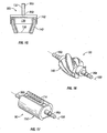
- Examples of other types of cutting features 114 practicable on the drum-type cutting tool 90a include: "TI" type cutting features 114b on a rotary drum type cutting tool (see Fig. 6 ); "scallop" type cutting features 114c with hypo-tubes on a rotary drum type cutting tool (see Figs. 7A and 7B ); and "square scallop” type cutting features 114d (see Fig. 8 ) and "round scallop” type cutting features 114e (see Fig. 9 ), both useful for the cutting surface of a rotary drum type cutting tool 90a.
- tissue-cutting tools 90 are rotary drum type cutting tools 90a.
- rotating shaft cutting tools 90b (see Figs. 10-14 ) may be used.
- a rotating shaft cutting tool 90b comprises a rotatable shaft 120 having a drive end 122 for engaging the drive means 160 and a tool end 124 for mounting the tissue cutting surface 126 and cutting features 128.
- Figs 10A and 10B illustrate a rotating shaft-type tissue cutter tool 90b and harvester housing 130, and the rotating shaft-type tool 90b installed in a type of tissue harvester assembly 20b and connected to a drive means 160.
- the tool 90b has a side cutting bit feature 128 and is installable in a shear block type harvester housing 130.
- Other configurations of rotating shaft-type tissue cutter tools 90b are practicable in the present harvester assembly 20b. Examples include: a fine scallop hypo-tube rotating shaft-type tissue cutter tool ( Fig. 11 ); a course scallop hypo-tube rotating shaft-type tissue cutter tool ( Fig. 12 ); a course scallop solid shaft-type tissue cutter tool ( Fig.13 ); and alternative side cutting bit shaft-type tissue cutter tools ( Fig. 14 ).
- a rotating end-mill cutting tool 90c comprises a rotatable shaft 132 having a drive end 96a for engaging the drive means 160 ( Fig. 10B ) and a tool end 96b for mounting a cutting drum 136.
- the cutting drum 136 is cylindrical and has an axis disposed coaxially with the drive and tool shaft ends 96a and 96b.
- the tool end 96b is attached at one end of the cutting drum 136 and the other end of the cutting drum 136 mounts a tissue cutting surface 138.
- the tissue-cutting surface can be constructed to have cutting features 114 similar to those practicable on the rotating drum type cutter 90a noted above.
- One of ordinary skill in the art is readily able to select from and adapt said cutting features 114 for incorporation onto the cutting surface 138 of a rotating end-mill cutting tool 90c of the present invention 10.
- the drum 136 has an outer circumferential surface that is closely receivable in a width of the interior space of the end mill housing 140 associated depth alignment means 142.
- the cutting drum 136 of the end mill tissue cutting tool 90c illustrated in Fig. 15 is a tapered cylinder proximate its tissue cutting surface 138.
- centrifugal force can facilitate the migration of excised tissue particles passing through the cutting surface 138 into the interior of the drum (shown in phantom) and up the interior walls and away from the cutting surface 138. This will help to prevent clogging certain of the cutting features 114 with excised tissue particles.
- Alternative cutting tools 90 may be utilized include a modified rough-cutting end mill 148 and a razor cutter with serrations 150.
- a modified end mill 148 exhibits cutting characteristics of a typical end mill cutting tool as shown in Figure 15 , however the modified end mill 148 exhibits a cylindrical shape and an axis 100 disposed coaxially with the drive and tool shaft ends 96a & 96b, similar to the rotating shaft cutter of Figure 5A .
- the drive means 160 is typically a drive motor of some type (e.g., electric or pneumatic) for rotating the tissue-cutting tool in the harvester housing 50 & 140.
- the drive means 160 may be integral to (see Figs. 18A and 18B ) or separate from (see Fig. 10B ) the harvester housing 50 & 140.
- a handle 162 may be connected or formed to the housing 50 in order for a user to more easily grasp and position the harvester assembly 20.
- a port 170 may be provided within the cutter 90 to draw tissue that has been collected by the cutter 90 out of the housing 50. While the port 170 has been shown in the center of the cutter 90 along its axis of rotation in this embodiment, it is to be understood that multiple mechanisms for removing tissue from the housing are envisioned and described further herein.
- a housing mounting 166 is provided for stability and support to the user during operation of the harvester 20. Skid plates 164 are provided to ease in positioning of the cutter 90 at the tissue site, and to further aid in adjustment of the cutter 90 depth, especially when a shim stack 59, or other adjustment means known in the art, are provided external of the cutter 90.
- FIGS 20A , 20B, and 20C illustrate a tissue particle collector 30, which may be comprised of a port 170 positioned within or near the drive means of the cutter 90, and which may be accessible by a particle retriever 172, such as a syringe.
- the particle retriever 172 may then be used to inject or otherwise instill the tissue collected into a nano-graft cell 40, as shown in Figure 1 .
- Various mediums may be utilized to suspend the tissue within the tissue particle collector 30, and subsequently the nano-graft cell 40. Such mediums may include, but are not necessarily limited to, saline.
- FIGs 21-27 Alternative embodiments of the tissue particle collector 30 for collecting tissue from the tissue particle harvester are illustrated in Figures 21-27 .
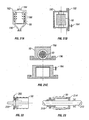
- a separate flushing container 180 may be utilized to retrieve tissue from the cutter 90.
- the cutter 90 is removed from the harvester housing 50 ( Fig. 2 ), and placed into the flushing container 180.
- a cap 182, or other cover, is screwed or otherwise secured to the container 180.
- a liquid medium, such as saline is then flushed through a port 184 or luer, which may be integrated with the cap 182, or otherwise introduced into the container 180, and is directed towards the inner diameter and outer diameter of the cutter 90 by jets 186 or channels within the container 180.
- An integral flushing container 190 allows for collection of tissue without removal of the cutter 90 from its housing 50 ( Fig. 2 ).
- the cutter 90 has a solid filled core.
- a gasketed cap 192 is fitted over the integral flushing container 190, which may be the housing 50 having a receptor for the gasket cap 192, after tissue is cut from the donor site.
- the housing 50, with the cutter 90 in place, is removed from the tissue particle harvester 20 and fluid, which may be saline, is injected into the flushing container 190 through a luer fitting 194, or port.
- the flushing container 190 is manually agitated, by hand or by a mechanical agitator known in the art.
- the tissue that has been cut by the cutter 90 is now suspended in the fluid which has been injected, at which point it may be drawn out of the integral flushing container 190 through the luer fitting 194 by means of a syringe or similar device known in the art.
- FIG. 21C An alternative embodiment of an integral flushing container 190 is illustrated in Figure 21C .
- a core filled cutter 90 is utilized to remove tissue from the donor site.
- a cap 196 which may be comprised of silicone or a material of similar physical characteristics is placed over the open-cutting face of the housing 50.
- the housing may include a luer for injecting fluid, such as saline, which is then agitated by running the motor of the cutter 90. The agitation results in suspension of the tissue cut by the cutter 90 in the fluid, which may then be drawn out by through the luer 194 by a syringe or similar device, for insertion into a nano-graft cell 40.
- Collection of tissue from the cutter 90 may also be accomplished by use of a bristled plunger 200, as shown in Figure 22 .
- the bristled plunger 200 is insertable into the inner diameter of a cutter 90 having a hollow core. After collection of tissue by the cutter 90, the plunger 200 is moved, manually or mechanically, into the inner diameter of the cutter 90. Bristles 202 draw out the tissue that has been collected in the inner diameter of the cutter 90 as the plunger is retracted from the inner diameter of the cutter 90.
- the plunger 200 may be retractable into an adjacent container (not shown) that may be filled with a fluid, such as saline, for suspension of the tissue collected from the cutter 90.
- a luer (not shown) may be incorporated into the adjacent container for retrieval of the tissue suspended fluid by a syringe or similar device, and for injection of the fluid prior to tissue collection.
- a standard plunger 210 rides over the shaft 212 of the cutter 90 assembly.
- the shaft 212, plunger 210, and cutter 90 all rotate together during operation of the harvester assembly 20.
- the plunger 210 is moved across the inner diameter of the cutter 90 towards a removable end cap 214.
- the end cap 214 is removed from the harvester assembly 20 so the tissue may be removed or flushed out by means of a syringe or other process well known to those skilled in the art.
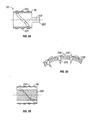
- tissue particle collector 30 is the internal flushing channels 220 as illustrated in Figure 24 .
- An internal core 222 is positioned within the cutter 90.
- the core 222 which remains stationary during rotation of the cutter 90, is toleranced tightly to the inner diameter of the cutter 90 while still allowing for free rotation of the cutter 90.
- Tissue enters channels 220 through openings 224 in the cutter during operation of the cutter 90. Fluid is flushed through the channels 220 during operation of the cutter into a collection chamber (not shown) for later removal to the wound site. It is to be understood that the fluid may also be flushed through the channels 220 when the cutter 90 is not being operated.
- Figure 25 illustrates a spring-loaded plunger 230 that may be utilized to retrieve tissue particles from the cutter 90 after removal from the donor site.
- the spring-loaded plungers 230 are positioned within the recesses 232 of the cutting scoops 234 of a stationary core 236 of the cutter 90. After collection of tissue from the donor site, the core 236 is moved radially, or alternatively axially, until the plungers 230 pop out and remove tissue particles from the recesses 232. It is to be understood that the plungers 230 may be cam activated, or by similar mechanisms utilized by those skilled in the art, to extract tissue that has been collected within the recesses 232.
- Tissue may be removed from the harvester 20 by means of a static internal screw 240, as illustrated in Figure 26 .
- a static internal screw 240 which may be described by those skilled in the art as a reverse Archimedes screw, is positioned within the inner diameter of the cutter 90.
- the static internal screw 240 moves particles to one end of the cutter for collection by wiping the inner diameter of the cutter 90. It is envisioned that the screw 240 may be inserted after the tissue has been collected in order to wipe the inner diameter of the cutter 90, and move the tissue to one end of the cutter 90 for collection.
- manual agitation may also be utilized to remove tissue that has been collected by the cutter 90.
- the cutter 90 is removed from the harvester 20 and placed in a container holding fluid, such as saline or a similar fluid.
- the cutter 90 is spun within the container to remove particles into the fluid.
- the container may then be centrifuged to separate the tissue particles from the fluid or alternatively, the fluid may be passed through a filter to remove the tissue from the fluid.
Landscapes
- Health & Medical Sciences (AREA)
- Surgery (AREA)
- Life Sciences & Earth Sciences (AREA)
- Molecular Biology (AREA)
- General Health & Medical Sciences (AREA)
- Transplantation (AREA)
- Engineering & Computer Science (AREA)
- Biomedical Technology (AREA)
- Heart & Thoracic Surgery (AREA)
- Medical Informatics (AREA)
- Plastic & Reconstructive Surgery (AREA)
- Animal Behavior & Ethology (AREA)
- Nuclear Medicine, Radiotherapy & Molecular Imaging (AREA)
- Public Health (AREA)
- Veterinary Medicine (AREA)
- Surgical Instruments (AREA)
- Sampling And Sample Adjustment (AREA)
- Materials For Medical Uses (AREA)
- Medicines Containing Material From Animals Or Micro-Organisms (AREA)
- Investigating Or Analysing Biological Materials (AREA)
Claims (6)
- System zur Transplantation von Hautgewebe, mit:einer Gewebepartikel-Ernteanordnung (20) zum Schneiden von Gewebepartikeln aus Hautgewebe;einer Gewebepartikel-Sammeleinrichtung (30) zum Aufnehmen, Trennen und Sammeln der Gewebepartikel; undeiner in Kammern unterteilten Aufbereitungsvorrichtung (40) zum Aufnehmen der gesammelten Gewebepartikel und zum Kultivieren des Wachstums eines Hautgewebetransplantats;wobei die Gewebepartikel-Ernteanordnung enthält:ein Gewebe-Schneidwerkzeug (90) mit einer Schneidfläche (94), wobei die Schneidfläche (94) vorgesehen ist, um mit der Gewebeprobe in Kontakt zu kommen und Gewebepartikel geeigneter Größe aus dieser zu schneiden; undeine Schneidwalze (90a);dadurch gekennzeichnet, dass die Gewebepartikel-Ernteanordnung weiters enthält:ein Erntegehäuse (50) mit einem Innenraum, wobei das Gehäuse vorgesehen ist, um mit einer Hautgewebeprobe, aus der Gewebepartikel geerntet werden sollen, in Kontakt zu kommen und um ein Gewebe-Schneidwerkzeug (90) in einer in Bezug auf die Hautgewebeprobe richtigen Position zu halten;ein Antriebsmittel (160) zum Drehen des Gewebe-Schneidwerkzeugs;wobei das Gewebe-Schneidwerkzeug weiters eine Drehwelle (96) mit einer Antriebsseite (96a) zum Eingriff mit dem Antriebsmittel und eine Werkzeugseite (96b) zum Anbringen der Schneidwalze (90a) enthält, wobei die Schneidwalze (90a) eine Achse (100) hat, die koaxial mit der Werkzeugseite (96b) der Drehwelle (96) angeordnet ist und eine äußere Umfangsfläche und einen Durchmesser aufweist, die in einer Breite des Innenraums des Gehäuses (50) genau passend aufnehmbar sind, und wobei die Schneidwalze (90a) eine Scheibe (90c) am Walzenende hat, die von der Antriebsseite (96a) der Drehwelle (96) entfernt angeordnet ist und von der Gewebe-Schneidfläche (94) definiert wird.
- Gewebepartikel-Ernteanordnung (20) nach Anspruch 1, wobei das Erntegehäuse (50) eine Öffnung (54) zum Drücken gegen eine Hautgewebeschicht der Gewebeprobe und zum Aufnehmen dieser enthält.
- Gewebepartikel-Ernteanordnung (20) nach Anspruch 1, wobei das Gewebe-Schneidwerkzeug (90) weiters eine Drehwelle (96) mit einer Antriebsseite (96a) zum Eingriff mit dem Antriebsmittel (160) und eine Werkzeugseite (96b) zum Anbringen der Gewebe-Schneidfläche (94) aufweist.
- Gewebepartikel-Ernteanordnung (20) nach Anspruch 2, wobei ein Teil der Gewebe-Schneidfläche (94) von der Öffnung (54) vorsteht, und wobei die Öffnung (54) mit der Ernteanordnung (20) einstellbar im Eingriff steht, so dass die Gewebe-Schneidfläche (94) um ungefähr 0,01 bis 0,9 mm von der Ernteanordnung (20) vorsteht.
- Gewebepartikel-Ernteanordnung (20) nach Anspruch 2, wobei die Antriebsseite (96a) einstellbar ist, so dass ein Teil der Gewebe-Schneidfläche (94) um einen Abstand von ungefähr 0,01 bis 0,9 mm durch die Öffnung (54) der Ernteanordnung (20) vorsteht.
- Gewebepartikel-Ernteanordnung (20) nach Anspruch 1, wobei das Gewebe-Schneidwerkzeug (90) weiters eine Drehwelle (96) mit einer Antriebsseite (96a) zum Eingriff mit dem Antriebsmittel (160) und eine Werkzeugseite (96b) zum Anbringen einer Schneidwalze (90a) enthält, wobei die Schneidwalze (90a) eine Achse (100) hat, die koaxial mit der Werkzeugseite (96b) der Drehwelle (96) angeordnet ist und eine von der Gewebe-Schneidfläche (94) definierte, äußere Umfangsfläche und eine durchgehende Breite aufweist, die in einer Breite des Innenraums des Gehäuses (50) genau passend aufnehmbar ist.
Applications Claiming Priority (2)
| Application Number | Priority Date | Filing Date | Title |
|---|---|---|---|
| US10/673,661 US7666134B2 (en) | 2002-09-28 | 2003-09-29 | System and method for transplantation of dermal tissue |
| PCT/US2004/031802 WO2005033273A2 (en) | 2003-09-29 | 2004-09-28 | System for transplantation of dermal tissue |
Publications (3)
| Publication Number | Publication Date |
|---|---|
| EP1680032A2 EP1680032A2 (de) | 2006-07-19 |
| EP1680032A4 EP1680032A4 (de) | 2008-05-21 |
| EP1680032B1 true EP1680032B1 (de) | 2009-10-21 |
Family
ID=34422043
Family Applications (1)
| Application Number | Title | Priority Date | Filing Date |
|---|---|---|---|
| EP04789154A Expired - Lifetime EP1680032B1 (de) | 2003-09-29 | 2004-09-28 | System zur transplantation von hautgewebe |
Country Status (9)
| Country | Link |
|---|---|
| US (2) | US7666134B2 (de) |
| EP (1) | EP1680032B1 (de) |
| JP (1) | JP4739212B2 (de) |
| AT (1) | ATE446056T1 (de) |
| AU (1) | AU2004278745B2 (de) |
| CA (1) | CA2540526C (de) |
| DE (1) | DE602004023747D1 (de) |
| WO (1) | WO2005033273A2 (de) |
| ZA (1) | ZA200602627B (de) |
Families Citing this family (43)
| Publication number | Priority date | Publication date | Assignee | Title |
|---|---|---|---|---|
| US8501396B2 (en) | 2001-11-05 | 2013-08-06 | Medgenics Medical Israel Ltd. | Dermal micro-organs, methods and apparatuses for producing and using the same |
| US7468242B2 (en) * | 2001-11-05 | 2008-12-23 | Medgenics, Inc. | Dermal micro organs, methods and apparatuses for producing and using the same |
| US8088568B2 (en) | 2001-11-05 | 2012-01-03 | Medgentics, Inc. | Dermal micro-organs, methods and apparatuses for producing and using the same |
| US20040175690A1 (en) * | 2003-03-03 | 2004-09-09 | Kci Licensing, Inc. | Tissue harvesting device and method |
| EP2377403A1 (de) | 2003-05-01 | 2011-10-19 | Medgenics, Inc. | Genetisch modifizierter dermisches mikroorgan-ausdrückender Faktor VIII |
| US20050101972A1 (en) * | 2003-11-06 | 2005-05-12 | University Of Florida Research Foundation, Inc. | Devices and systems for separating and preparing skin |
| EP2335650B1 (de) | 2003-12-11 | 2012-10-03 | Isto Technologies Inc. | Teilchenförmiges Knorpelsystem |
| WO2007025290A2 (en) | 2005-08-26 | 2007-03-01 | Isto Technologies, Inc. | Implants and methods for repair, replacement and treatment of joint disease |
| JP2009526201A (ja) * | 2006-01-26 | 2009-07-16 | コーネル・リサーチ・ファンデーション・インコーポレイテッド | 小試料操作用の微細加工されたツール |
| US8454948B2 (en) | 2006-09-14 | 2013-06-04 | Medgenics Medical Israel Ltd. | Long lasting drug formulations |
| WO2008033375A2 (en) * | 2006-09-14 | 2008-03-20 | Medgenics Ltd. | Long lasting drug formulations |
| US8163549B2 (en) | 2006-12-20 | 2012-04-24 | Zimmer Orthobiologics, Inc. | Method of obtaining viable small tissue particles and use for tissue repair |
| EP2134297B1 (de) | 2007-04-12 | 2017-03-08 | Zimmer, Inc. | Vorrichtung zur gewebereparatur |
| US8002779B2 (en) * | 2007-12-13 | 2011-08-23 | Zimmer Surgical, Inc. | Dermatome blade assembly |
| US8814881B2 (en) | 2007-12-13 | 2014-08-26 | Zimmer Surgical, Inc. | Dermatome with orientation guides |
| RU2011127676A (ru) | 2008-12-30 | 2013-02-10 | КейСиАй ЛАЙСЕНЗИНГ, ИНК. | Интенсификация процедуры микропереломов пониженным давлением для восстановления хряща |
| RU2011122956A (ru) | 2008-12-31 | 2013-02-10 | КейСиАй ЛАЙСЕНЗИНГ, ИНК. | Система для обеспечения потока текучей среды к нервным тканям |
| JP2013532152A (ja) | 2010-06-15 | 2013-08-15 | メドジェニクス・メディカル・イスラエル・リミテッド | 長期持続性の医薬製剤 |
| US9610093B2 (en) | 2010-08-06 | 2017-04-04 | Kci Licensing, Inc. | Microblister skin grafting |
| US9597111B2 (en) | 2010-08-06 | 2017-03-21 | Kci Licensing, Inc. | Methods for applying a skin graft |
| US9173674B2 (en) | 2010-08-06 | 2015-11-03 | MoMelan Technologies, Inc. | Devices for harvesting a skin graft |
| US8978234B2 (en) | 2011-12-07 | 2015-03-17 | MoMelan Technologies, Inc. | Methods of manufacturing devices for generating skin grafts |
| US8926631B2 (en) | 2010-08-06 | 2015-01-06 | MoMelan Technologies, Inc. | Methods for preparing a skin graft without culturing or use of biologics |
| US8562626B2 (en) | 2010-08-06 | 2013-10-22 | MoMelan Technologies, Inc. | Devices for harvesting a skin graft |
| US8617181B2 (en) | 2010-08-06 | 2013-12-31 | MoMelan Technologies, Inc. | Methods for preparing a skin graft |
| US20120197267A1 (en) | 2011-01-27 | 2012-08-02 | MoMelan Technologies, Inc. | Devices for generating and transferring micrografts and methods of use thereof |
| WO2012145504A1 (en) * | 2011-04-20 | 2012-10-26 | Kci Licensing, Inc. | Skin graft devices and methods |
| US20140178343A1 (en) | 2012-12-21 | 2014-06-26 | Jian Q. Yao | Supports and methods for promoting integration of cartilage tissue explants |
| EP2967627B1 (de) | 2013-03-14 | 2017-08-30 | KCI Licensing, Inc. | Saugfähige substrate zur entnahme von hauttransplantaten |
| EP3089681B1 (de) | 2013-12-31 | 2021-09-08 | 3M Innovative Properties Company | Flüssigkeitsunterstützte entnahme eines hautimplantats |
| WO2015103043A1 (en) | 2013-12-31 | 2015-07-09 | Kci Licensing, Inc. | Sensor systems for skin graft harvesting |
| RU2014101757A (ru) * | 2014-01-21 | 2015-07-27 | Дауд Меджидович Шамов | Способ восстановления ткани |
| WO2015184146A1 (en) * | 2014-05-30 | 2015-12-03 | Sameh Mesallum | Systems for automated biomechanical computerized surgery |
| WO2016164890A1 (en) | 2015-04-09 | 2016-10-13 | Kci Licensing, Inc. | Soft-tack, porous substrates for harvesting skin grafts |
| US10905458B2 (en) | 2015-06-08 | 2021-02-02 | Covidien Lp | Tissue-removing catheter, tissue-removing element, and method of making same |
| US10905459B2 (en) | 2015-06-08 | 2021-02-02 | Covidien Lp | Tissue-removing catheter, tissue-removing element, and method of making same |
| ITUB20151961A1 (it) * | 2015-07-06 | 2017-01-06 | Mario Goisis | Kit per procedure chirurgiche di liposuzione e lipofilling |
| US10631894B2 (en) | 2015-07-15 | 2020-04-28 | Covidien Lp | Tissue-removing catheter, tissue-removing element, and method of making same |
| US11006974B2 (en) | 2015-11-03 | 2021-05-18 | Kci Licensing, Inc. | Devices for creating an epidermal graft sheet |
| US10507036B2 (en) | 2016-01-13 | 2019-12-17 | Covidien LLP | Tissue-removing catheter, tissue-removing element, and method of making same |
| SE541418C2 (en) | 2016-01-22 | 2019-09-24 | S2Medical Ab | Minimally invasive tissue harvesting device |
| CN120837237A (zh) | 2017-07-26 | 2025-10-28 | 纽拉普缇夫治疗公司 | 创建用于向神经施用治疗剂的流体容纳场的装置和方法 |
| US12558115B2 (en) * | 2020-03-06 | 2026-02-24 | The Johns Hopkins University | Mechanism for dicing cartilage |
Family Cites Families (16)
| Publication number | Priority date | Publication date | Assignee | Title |
|---|---|---|---|---|
| US3037509A (en) * | 1957-11-25 | 1962-06-05 | Schutz Emil Robert | Apparatus for removing skin particles from a donor area and applying the particles to a recipient area |
| US3640279A (en) | 1967-12-07 | 1972-02-08 | Warren F Brown | Skin graft cutting method and machine |
| US3824745A (en) * | 1972-08-21 | 1974-07-23 | A Hutchins | Suction system for abrading tool |
| US4285618A (en) * | 1979-10-12 | 1981-08-25 | Shanley Stephen E Jr | Rotary milling cutter |
| DD251915A1 (de) * | 1986-08-06 | 1987-12-02 | Spezialmaschinenfabrik Veb | Vorrichtung zum enthaeuten von schweinen |
| US4784056A (en) * | 1988-03-14 | 1988-11-15 | Towsend Engineering Company | Safety device for meat skinning machines |
| US5030201A (en) | 1989-11-24 | 1991-07-09 | Aubrey Palestrant | Expandable atherectomy catheter device |
| US5152757A (en) * | 1989-12-14 | 1992-10-06 | Brigham And Women's Hospital | System for diagnosis and treatment of wounds |
| RU2135191C1 (ru) * | 1990-04-24 | 1999-08-27 | Ортек Интернэшнл, Инк. | Композиционный эквивалент живой кожи, способ его получения, тест-набор |
| US5269785A (en) * | 1990-06-28 | 1993-12-14 | Bonutti Peter M | Apparatus and method for tissue removal |
| DE4329380C1 (de) * | 1993-09-01 | 1995-01-26 | Nordischer Maschinenbau | Verfahren zum Abtrennen einer Oberflächenschicht und Vorrichtung zur Durchführung des Verfahrens |
| US6050972A (en) * | 1996-05-20 | 2000-04-18 | Percusurge, Inc. | Guidewire inflation system |
| US5827217A (en) | 1996-09-04 | 1998-10-27 | Silver; Frederick H. | Process and apparatus for harvesting tissue for processing tissue and process and apparatus for re-injecting processed tissue |
| IL122016A (en) * | 1997-10-22 | 2001-09-13 | Tav Tech Ltd | Apparatus for dermal abrasion |
| CA2638625C (en) | 1999-12-03 | 2012-07-24 | University Of Leeds | Fixation technology for bone repair |
| US6391034B1 (en) * | 2000-08-15 | 2002-05-21 | University Of South Florida | Surgical device and method for removing unwanted tissue |
-
2003
- 2003-09-29 US US10/673,661 patent/US7666134B2/en active Active
-
2004
- 2004-09-28 WO PCT/US2004/031802 patent/WO2005033273A2/en not_active Ceased
- 2004-09-28 AT AT04789154T patent/ATE446056T1/de not_active IP Right Cessation
- 2004-09-28 AU AU2004278745A patent/AU2004278745B2/en not_active Ceased
- 2004-09-28 CA CA2540526A patent/CA2540526C/en not_active Expired - Lifetime
- 2004-09-28 DE DE602004023747T patent/DE602004023747D1/de not_active Expired - Lifetime
- 2004-09-28 JP JP2006528311A patent/JP4739212B2/ja not_active Expired - Fee Related
- 2004-09-28 EP EP04789154A patent/EP1680032B1/de not_active Expired - Lifetime
-
2006
- 2006-03-30 ZA ZA200602627A patent/ZA200602627B/xx unknown
-
2010
- 2010-02-15 US US12/705,668 patent/US8623031B2/en not_active Expired - Fee Related
Also Published As
| Publication number | Publication date |
|---|---|
| AU2004278745A1 (en) | 2005-04-14 |
| AU2004278745B2 (en) | 2010-09-16 |
| EP1680032A4 (de) | 2008-05-21 |
| US20040172045A1 (en) | 2004-09-02 |
| EP1680032A2 (de) | 2006-07-19 |
| JP2007507255A (ja) | 2007-03-29 |
| US20100145360A1 (en) | 2010-06-10 |
| CA2540526C (en) | 2012-11-27 |
| DE602004023747D1 (de) | 2009-12-03 |
| ATE446056T1 (de) | 2009-11-15 |
| US8623031B2 (en) | 2014-01-07 |
| CA2540526A1 (en) | 2005-04-14 |
| ZA200602627B (en) | 2008-12-31 |
| JP4739212B2 (ja) | 2011-08-03 |
| WO2005033273A2 (en) | 2005-04-14 |
| WO2005033273A3 (en) | 2005-08-04 |
| HK1095074A1 (en) | 2007-04-27 |
| US7666134B2 (en) | 2010-02-23 |
Similar Documents
| Publication | Publication Date | Title |
|---|---|---|
| AU2004278745B2 (en) | System for transplantation of dermal tissue | |
| US10932813B2 (en) | Minimally invasive tissue harvesting device | |
| US7611473B2 (en) | Tissue extraction and maceration device | |
| CA2449227C (en) | Tissue biopsy and processing device | |
| JP2022186766A (ja) | 非外傷的に形成された組織組成物、装置、ならびに調製および治療の方法 | |
| EP4028035A1 (de) | Verfahren und vorrichtung zur zellisolierung und isolierte zellen zur wundheilung | |
| HK1095074B (en) | System for transplantation of dermal tissue | |
| HK40001084B (en) | Minimally invasive tissue harvesting device | |
| HK40001084A (en) | Minimally invasive tissue harvesting device | |
| OA18827A (en) | Minimally invasive tissue harvesting device. |
Legal Events
| Date | Code | Title | Description |
|---|---|---|---|
| PUAI | Public reference made under article 153(3) epc to a published international application that has entered the european phase |
Free format text: ORIGINAL CODE: 0009012 |
|
| 17P | Request for examination filed |
Effective date: 20060406 |
|
| AK | Designated contracting states |
Kind code of ref document: A2 Designated state(s): AT BE BG CH CY CZ DE DK EE ES FI FR GB GR HU IE IT LI LU MC NL PL PT RO SE SI SK TR |
|
| DAX | Request for extension of the european patent (deleted) | ||
| REG | Reference to a national code |
Ref country code: HK Ref legal event code: DE Ref document number: 1095074 Country of ref document: HK |
|
| RIN1 | Information on inventor provided before grant (corrected) |
Inventor name: GIROUARD, MICHAEL Inventor name: ERIKSSON, ELOF Inventor name: KAGAN, JONATHAN Inventor name: JOHNSON, ROYCE Inventor name: MISHRA, AJIT Inventor name: OHIRA, MAKOTO |
|
| A4 | Supplementary search report drawn up and despatched |
Effective date: 20080423 |
|
| 17Q | First examination report despatched |
Effective date: 20080714 |
|
| GRAP | Despatch of communication of intention to grant a patent |
Free format text: ORIGINAL CODE: EPIDOSNIGR1 |
|
| GRAS | Grant fee paid |
Free format text: ORIGINAL CODE: EPIDOSNIGR3 |
|
| GRAA | (expected) grant |
Free format text: ORIGINAL CODE: 0009210 |
|
| AK | Designated contracting states |
Kind code of ref document: B1 Designated state(s): AT BE BG CH CY CZ DE DK EE ES FI FR GB GR HU IE IT LI LU MC NL PL PT RO SE SI SK TR |
|
| REG | Reference to a national code |
Ref country code: GB Ref legal event code: FG4D |
|
| REG | Reference to a national code |
Ref country code: CH Ref legal event code: EP |
|
| REG | Reference to a national code |
Ref country code: IE Ref legal event code: FG4D |
|
| REF | Corresponds to: |
Ref document number: 602004023747 Country of ref document: DE Date of ref document: 20091203 Kind code of ref document: P |
|
| REG | Reference to a national code |
Ref country code: HK Ref legal event code: GR Ref document number: 1095074 Country of ref document: HK |
|
| PG25 | Lapsed in a contracting state [announced via postgrant information from national office to epo] |
Ref country code: PT Free format text: LAPSE BECAUSE OF FAILURE TO SUBMIT A TRANSLATION OF THE DESCRIPTION OR TO PAY THE FEE WITHIN THE PRESCRIBED TIME-LIMIT Effective date: 20100222 Ref country code: SE Free format text: LAPSE BECAUSE OF FAILURE TO SUBMIT A TRANSLATION OF THE DESCRIPTION OR TO PAY THE FEE WITHIN THE PRESCRIBED TIME-LIMIT Effective date: 20091021 Ref country code: FI Free format text: LAPSE BECAUSE OF FAILURE TO SUBMIT A TRANSLATION OF THE DESCRIPTION OR TO PAY THE FEE WITHIN THE PRESCRIBED TIME-LIMIT Effective date: 20091021 Ref country code: ES Free format text: LAPSE BECAUSE OF FAILURE TO SUBMIT A TRANSLATION OF THE DESCRIPTION OR TO PAY THE FEE WITHIN THE PRESCRIBED TIME-LIMIT Effective date: 20100201 |
|
| PG25 | Lapsed in a contracting state [announced via postgrant information from national office to epo] |
Ref country code: SI Free format text: LAPSE BECAUSE OF FAILURE TO SUBMIT A TRANSLATION OF THE DESCRIPTION OR TO PAY THE FEE WITHIN THE PRESCRIBED TIME-LIMIT Effective date: 20091021 Ref country code: PL Free format text: LAPSE BECAUSE OF FAILURE TO SUBMIT A TRANSLATION OF THE DESCRIPTION OR TO PAY THE FEE WITHIN THE PRESCRIBED TIME-LIMIT Effective date: 20091021 |
|
| PG25 | Lapsed in a contracting state [announced via postgrant information from national office to epo] |
Ref country code: AT Free format text: LAPSE BECAUSE OF FAILURE TO SUBMIT A TRANSLATION OF THE DESCRIPTION OR TO PAY THE FEE WITHIN THE PRESCRIBED TIME-LIMIT Effective date: 20091021 Ref country code: BE Free format text: LAPSE BECAUSE OF FAILURE TO SUBMIT A TRANSLATION OF THE DESCRIPTION OR TO PAY THE FEE WITHIN THE PRESCRIBED TIME-LIMIT Effective date: 20091021 |
|
| PG25 | Lapsed in a contracting state [announced via postgrant information from national office to epo] |
Ref country code: EE Free format text: LAPSE BECAUSE OF FAILURE TO SUBMIT A TRANSLATION OF THE DESCRIPTION OR TO PAY THE FEE WITHIN THE PRESCRIBED TIME-LIMIT Effective date: 20091021 Ref country code: BG Free format text: LAPSE BECAUSE OF FAILURE TO SUBMIT A TRANSLATION OF THE DESCRIPTION OR TO PAY THE FEE WITHIN THE PRESCRIBED TIME-LIMIT Effective date: 20100121 Ref country code: DK Free format text: LAPSE BECAUSE OF FAILURE TO SUBMIT A TRANSLATION OF THE DESCRIPTION OR TO PAY THE FEE WITHIN THE PRESCRIBED TIME-LIMIT Effective date: 20091021 Ref country code: RO Free format text: LAPSE BECAUSE OF FAILURE TO SUBMIT A TRANSLATION OF THE DESCRIPTION OR TO PAY THE FEE WITHIN THE PRESCRIBED TIME-LIMIT Effective date: 20091021 |
|
| PLBE | No opposition filed within time limit |
Free format text: ORIGINAL CODE: 0009261 |
|
| STAA | Information on the status of an ep patent application or granted ep patent |
Free format text: STATUS: NO OPPOSITION FILED WITHIN TIME LIMIT |
|
| PG25 | Lapsed in a contracting state [announced via postgrant information from national office to epo] |
Ref country code: CZ Free format text: LAPSE BECAUSE OF FAILURE TO SUBMIT A TRANSLATION OF THE DESCRIPTION OR TO PAY THE FEE WITHIN THE PRESCRIBED TIME-LIMIT Effective date: 20091021 Ref country code: SK Free format text: LAPSE BECAUSE OF FAILURE TO SUBMIT A TRANSLATION OF THE DESCRIPTION OR TO PAY THE FEE WITHIN THE PRESCRIBED TIME-LIMIT Effective date: 20091021 |
|
| 26N | No opposition filed |
Effective date: 20100722 |
|
| PG25 | Lapsed in a contracting state [announced via postgrant information from national office to epo] |
Ref country code: GR Free format text: LAPSE BECAUSE OF FAILURE TO SUBMIT A TRANSLATION OF THE DESCRIPTION OR TO PAY THE FEE WITHIN THE PRESCRIBED TIME-LIMIT Effective date: 20100122 |
|
| PG25 | Lapsed in a contracting state [announced via postgrant information from national office to epo] |
Ref country code: IT Free format text: LAPSE BECAUSE OF FAILURE TO SUBMIT A TRANSLATION OF THE DESCRIPTION OR TO PAY THE FEE WITHIN THE PRESCRIBED TIME-LIMIT Effective date: 20091021 |
|
| PG25 | Lapsed in a contracting state [announced via postgrant information from national office to epo] |
Ref country code: MC Free format text: LAPSE BECAUSE OF NON-PAYMENT OF DUE FEES Effective date: 20100930 |
|
| REG | Reference to a national code |
Ref country code: CH Ref legal event code: PL |
|
| PG25 | Lapsed in a contracting state [announced via postgrant information from national office to epo] |
Ref country code: IE Free format text: LAPSE BECAUSE OF NON-PAYMENT OF DUE FEES Effective date: 20100928 Ref country code: LI Free format text: LAPSE BECAUSE OF NON-PAYMENT OF DUE FEES Effective date: 20100930 Ref country code: CH Free format text: LAPSE BECAUSE OF NON-PAYMENT OF DUE FEES Effective date: 20100930 |
|
| PG25 | Lapsed in a contracting state [announced via postgrant information from national office to epo] |
Ref country code: CY Free format text: LAPSE BECAUSE OF FAILURE TO SUBMIT A TRANSLATION OF THE DESCRIPTION OR TO PAY THE FEE WITHIN THE PRESCRIBED TIME-LIMIT Effective date: 20091021 |
|
| PG25 | Lapsed in a contracting state [announced via postgrant information from national office to epo] |
Ref country code: LU Free format text: LAPSE BECAUSE OF NON-PAYMENT OF DUE FEES Effective date: 20100928 Ref country code: HU Free format text: LAPSE BECAUSE OF FAILURE TO SUBMIT A TRANSLATION OF THE DESCRIPTION OR TO PAY THE FEE WITHIN THE PRESCRIBED TIME-LIMIT Effective date: 20100422 |
|
| PG25 | Lapsed in a contracting state [announced via postgrant information from national office to epo] |
Ref country code: TR Free format text: LAPSE BECAUSE OF FAILURE TO SUBMIT A TRANSLATION OF THE DESCRIPTION OR TO PAY THE FEE WITHIN THE PRESCRIBED TIME-LIMIT Effective date: 20091021 |
|
| REG | Reference to a national code |
Ref country code: FR Ref legal event code: PLFP Year of fee payment: 13 |
|
| REG | Reference to a national code |
Ref country code: FR Ref legal event code: PLFP Year of fee payment: 14 |
|
| REG | Reference to a national code |
Ref country code: FR Ref legal event code: PLFP Year of fee payment: 15 |
|
| PGFP | Annual fee paid to national office [announced via postgrant information from national office to epo] |
Ref country code: NL Payment date: 20200825 Year of fee payment: 17 |
|
| REG | Reference to a national code |
Ref country code: NL Ref legal event code: MM Effective date: 20211001 |
|
| PG25 | Lapsed in a contracting state [announced via postgrant information from national office to epo] |
Ref country code: NL Free format text: LAPSE BECAUSE OF NON-PAYMENT OF DUE FEES Effective date: 20211001 |
|
| PGFP | Annual fee paid to national office [announced via postgrant information from national office to epo] |
Ref country code: GB Payment date: 20220818 Year of fee payment: 19 Ref country code: DE Payment date: 20220616 Year of fee payment: 19 |
|
| PGFP | Annual fee paid to national office [announced via postgrant information from national office to epo] |
Ref country code: FR Payment date: 20220819 Year of fee payment: 19 |
|
| REG | Reference to a national code |
Ref country code: DE Ref legal event code: R119 Ref document number: 602004023747 Country of ref document: DE |
|
| GBPC | Gb: european patent ceased through non-payment of renewal fee |
Effective date: 20230928 |
|
| PG25 | Lapsed in a contracting state [announced via postgrant information from national office to epo] |
Ref country code: GB Free format text: LAPSE BECAUSE OF NON-PAYMENT OF DUE FEES Effective date: 20230928 |
|
| PG25 | Lapsed in a contracting state [announced via postgrant information from national office to epo] |
Ref country code: GB Free format text: LAPSE BECAUSE OF NON-PAYMENT OF DUE FEES Effective date: 20230928 Ref country code: FR Free format text: LAPSE BECAUSE OF NON-PAYMENT OF DUE FEES Effective date: 20230930 Ref country code: DE Free format text: LAPSE BECAUSE OF NON-PAYMENT OF DUE FEES Effective date: 20240403 |