EP1680609B1 - Fluiddämpfer - Google Patents
Fluiddämpfer Download PDFInfo
- Publication number
- EP1680609B1 EP1680609B1 EP04800427A EP04800427A EP1680609B1 EP 1680609 B1 EP1680609 B1 EP 1680609B1 EP 04800427 A EP04800427 A EP 04800427A EP 04800427 A EP04800427 A EP 04800427A EP 1680609 B1 EP1680609 B1 EP 1680609B1
- Authority
- EP
- European Patent Office
- Prior art keywords
- piece
- damper according
- turning piece
- fluidic damper
- cover piece
- Prior art date
- Legal status (The legal status is an assumption and is not a legal conclusion. Google has not performed a legal analysis and makes no representation as to the accuracy of the status listed.)
- Expired - Lifetime
Links
Images



Classifications
-
- E—FIXED CONSTRUCTIONS
- E05—LOCKS; KEYS; WINDOW OR DOOR FITTINGS; SAFES
- E05F—DEVICES FOR MOVING WINGS INTO OPEN OR CLOSED POSITION; CHECKS FOR WINGS; WING FITTINGS NOT OTHERWISE PROVIDED FOR, CONCERNED WITH THE FUNCTIONING OF THE WING
- E05F5/00—Braking devices, e.g. checks; Stops; Buffers
- E05F5/02—Braking devices, e.g. checks; Stops; Buffers specially for preventing the slamming of swinging wings during final closing movement, e.g. jamb stops
-
- F—MECHANICAL ENGINEERING; LIGHTING; HEATING; WEAPONS; BLASTING
- F16—ENGINEERING ELEMENTS AND UNITS; GENERAL MEASURES FOR PRODUCING AND MAINTAINING EFFECTIVE FUNCTIONING OF MACHINES OR INSTALLATIONS; THERMAL INSULATION IN GENERAL
- F16F—SPRINGS; SHOCK-ABSORBERS; MEANS FOR DAMPING VIBRATION
- F16F9/00—Springs, vibration-dampers, shock-absorbers, or similarly-constructed movement-dampers using a fluid or the equivalent as damping medium
- F16F9/32—Details
- F16F9/34—Special valve constructions; Shape or construction of throttling passages
- F16F9/3405—Throttling passages in or on piston body, e.g. slots
-
- F—MECHANICAL ENGINEERING; LIGHTING; HEATING; WEAPONS; BLASTING
- F16—ENGINEERING ELEMENTS AND UNITS; GENERAL MEASURES FOR PRODUCING AND MAINTAINING EFFECTIVE FUNCTIONING OF MACHINES OR INSTALLATIONS; THERMAL INSULATION IN GENERAL
- F16F—SPRINGS; SHOCK-ABSORBERS; MEANS FOR DAMPING VIBRATION
- F16F9/00—Springs, vibration-dampers, shock-absorbers, or similarly-constructed movement-dampers using a fluid or the equivalent as damping medium
- F16F9/32—Details
- F16F9/50—Special means providing automatic damping adjustment, i.e. self-adjustment of damping by particular sliding movements of a valve element, other than flexions or displacement of valve discs; Special means providing self-adjustment of spring characteristics
- F16F9/512—Means responsive to load action, i.e. static load on the damper or dynamic fluid pressure changes in the damper, e.g. due to changes in velocity
-
- E—FIXED CONSTRUCTIONS
- E05—LOCKS; KEYS; WINDOW OR DOOR FITTINGS; SAFES
- E05F—DEVICES FOR MOVING WINGS INTO OPEN OR CLOSED POSITION; CHECKS FOR WINGS; WING FITTINGS NOT OTHERWISE PROVIDED FOR, CONCERNED WITH THE FUNCTIONING OF THE WING
- E05F5/00—Braking devices, e.g. checks; Stops; Buffers
- E05F5/06—Buffers or stops limiting opening of swinging wings, e.g. floor or wall stops
- E05F5/10—Buffers or stops limiting opening of swinging wings, e.g. floor or wall stops with piston brakes
-
- E—FIXED CONSTRUCTIONS
- E05—LOCKS; KEYS; WINDOW OR DOOR FITTINGS; SAFES
- E05Y—INDEXING SCHEME ASSOCIATED WITH SUBCLASSES E05D AND E05F, RELATING TO CONSTRUCTION ELEMENTS, ELECTRIC CONTROL, POWER SUPPLY, POWER SIGNAL OR TRANSMISSION, USER INTERFACES, MOUNTING OR COUPLING, DETAILS, ACCESSORIES, AUXILIARY OPERATIONS NOT OTHERWISE PROVIDED FOR, APPLICATION THEREOF
- E05Y2201/00—Constructional elements; Accessories therefor
- E05Y2201/20—Brakes; Disengaging means; Holders; Stops; Valves; Accessories therefor
- E05Y2201/21—Brakes
-
- E—FIXED CONSTRUCTIONS
- E05—LOCKS; KEYS; WINDOW OR DOOR FITTINGS; SAFES
- E05Y—INDEXING SCHEME ASSOCIATED WITH SUBCLASSES E05D AND E05F, RELATING TO CONSTRUCTION ELEMENTS, ELECTRIC CONTROL, POWER SUPPLY, POWER SIGNAL OR TRANSMISSION, USER INTERFACES, MOUNTING OR COUPLING, DETAILS, ACCESSORIES, AUXILIARY OPERATIONS NOT OTHERWISE PROVIDED FOR, APPLICATION THEREOF
- E05Y2201/00—Constructional elements; Accessories therefor
- E05Y2201/20—Brakes; Disengaging means; Holders; Stops; Valves; Accessories therefor
- E05Y2201/252—Type of friction
- E05Y2201/254—Fluid or viscous friction
- E05Y2201/256—Fluid or viscous friction with pistons or vanes
-
- E—FIXED CONSTRUCTIONS
- E05—LOCKS; KEYS; WINDOW OR DOOR FITTINGS; SAFES
- E05Y—INDEXING SCHEME ASSOCIATED WITH SUBCLASSES E05D AND E05F, RELATING TO CONSTRUCTION ELEMENTS, ELECTRIC CONTROL, POWER SUPPLY, POWER SIGNAL OR TRANSMISSION, USER INTERFACES, MOUNTING OR COUPLING, DETAILS, ACCESSORIES, AUXILIARY OPERATIONS NOT OTHERWISE PROVIDED FOR, APPLICATION THEREOF
- E05Y2201/00—Constructional elements; Accessories therefor
- E05Y2201/20—Brakes; Disengaging means; Holders; Stops; Valves; Accessories therefor
- E05Y2201/262—Type of motion, e.g. braking
- E05Y2201/264—Type of motion, e.g. braking linear
-
- E—FIXED CONSTRUCTIONS
- E05—LOCKS; KEYS; WINDOW OR DOOR FITTINGS; SAFES
- E05Y—INDEXING SCHEME ASSOCIATED WITH SUBCLASSES E05D AND E05F, RELATING TO CONSTRUCTION ELEMENTS, ELECTRIC CONTROL, POWER SUPPLY, POWER SIGNAL OR TRANSMISSION, USER INTERFACES, MOUNTING OR COUPLING, DETAILS, ACCESSORIES, AUXILIARY OPERATIONS NOT OTHERWISE PROVIDED FOR, APPLICATION THEREOF
- E05Y2201/00—Constructional elements; Accessories therefor
- E05Y2201/40—Motors; Magnets; Springs; Weights; Accessories therefor
- E05Y2201/47—Springs
- E05Y2201/474—Compression springs
Definitions
- the invention relates to a fluidic damper which is used in movable components of a piece of furniture, for example a drawer or a door of wardrobe, It prevents the movable components from shutting with excessive force that would otherwise damage the components and generate undesired noise.
- a movable component of a piece of furniture such as a drawer of a desk, or a door of a wardrobe generates a loud bang when it slams shut with excessive force. Such noise is distracting and a nuisance. Sometimes, the same piece of furniture may even be damaged as a result of such forceful action. It is, therefore, desirable to shut a door or a drawer in a more controlled manner.
- European Patent Application EP 1236 925 A2 discloses a damper assembly for the use in connection with drawer slides, and doors for cupboarbs.
- the damper assembly comprises a cylinder of uniform bore adapted to receive a piston in a sealing engagement with the bore and to move axially of the bore, the piston being provided with a piston rod in sealing engagement with a bush acting to close one end of the bore, the opposite end being permanently closed.
- Part of the piston termed as the piston ring by the inventor, is made of a resiliently deformable material which flattens under compressive force and the same part is pressed against the inner wall of the cylinder to provide frictional force during the inward stroke of the piston into the cylinder.
- the disadvantage of this sort of damper assembly is that the piston ring is highly prone to frictional wear and tear.
- a hydraulic or fluidic damper normally has a cylindrical housing within which a piston is movable in a linear fashion. The same piston is attached to a form of mechanism for providing resistive force on the piston.
- the mechanism is usually a cylindrical block or a disc, which spans across the entire cross section of the cylinder with slight spatial allowance between the inner wall of the housing and the peripheral surface of the mechanism.
- the interior space of the housing is filled with a viscous fluid, so when the mechanism moves within the interior space, it experiences some degree of drag owing to its obstruction against fluid flow from one side of the mechanism to another.
- the mechanism is less susceptible to wear and tear since the inner wall of the housing is lubricated with the same viscous fluid that induces the drag force for the mechanism.
- a conventional fluidic damper is designed to resist motion of both inward and outward stroke of the piston.
- the invention is a fluidic damper which comprises a closed cylinder containing a valve mechanism.
- the valve mechanism is attached to a piston rod, a portion of which (the piston rod) emerges through an opening in one end wall of the cylinder.
- the valve mechanism comprises:-
- the turning piece is structurally connected to the cover piece by means of claws extending from the cover piece to the said turning piece.
- the guide member is a ridge and it fits to a channel on the inner edge of the turning piece. In another embodiment, the guide member is a groove and the retention mechanism is a knob extending from the inner surface of the turning piece.
- the axle is a hollow shaft to receive the piston rod.
- the fluidic damper has an additional spring which connects the closed end of the cylinder to the assembly of valve mechanism and piston rod to help the piston rod to restore to its original position before being depressed.
- the invention is a fluidic damper which consists of a cylinder (100) having a bore (130) through its longitudinal section for receiving a piston rod (110). One end of the cylinder (100) is closed while a portion of the piston rod (110) emerges through an opening at the other end. The remaining portion of the piston rod (110) lies inside the cylinder (100) and is mounted with a valve mechanism (90). The unoccupied space in the bore (130) is filled with a fluid and the interior of the cylinder (100) is kept fluid tight with a seal (140) flanging the opening.
- the closed end of the cylinder (100) is connected to the assembly of piston rod (110) and valve mechanism (90), with a spring (120).
- the function of the spring (120) is to push the piston rod (110) back to its fully extended position when the piston rod (110) is not depressed.
- the external end of the piston rod (110) may be attached to the movable part of the furniture and the piston rod (110), in this case, extends together with the movable part of the furniture without a need of having an additional spring to push the piston rod (110) out of the cylinder bore (130).
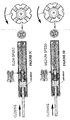
- the valve mechanism (90) essentially consists of a disc portion (10), and an annular cover piece (20) that turns about the axis joining the center of the two when the valve mechanism (90) exceeds certain speed in the fluid-filled bore.
- the disc portion (10) is placed across the bore (130) inside the cylinder (100) with a surface facing the closed end of the cylinder (100), Preferably, the disc portion (10) should cover up the entire inner cross section of the bore (130). Part of the circular periphery of the disc portion (10) is removed to allow the fluid to escape from one side of the disc portion to the other when the disc portion (10) moves along the bore (130). The disc portion (10) may be further punctuated to create more fluid passages or openings.
- a hollow shaft (15), forming a unitary piece with the said disc portion (10), is disposed on the surface of the said disc which faces the closed end of the cylinder (100) and extends perpendicularly from the said surface. It is used to receive the piston rod (110).
- the annular cover piece (20) is used to adjust the area of which the fluid can flow through the disc portion (IO). It slips onto hollow shaft (15) and is disposed adjacent to the disc portion (10). At one position, the cover piece (20) will cover the maximum area of which the fluid can flow through, and as a result, the valve mechanism (90) will experience maximum drag force as showN in Figure 2B. However, as the cover piece (20) begins to rotate in a direction, it slowly uncovers the openings. In the same direction, it slowly rotates to another position at which maximum flow of fluid can be achieved. At this position, most openings will be open.
- the cover piece (20) was to rotate from the position at which maximum flow of fluid through the disc (10) is achieved, in the opposite direction, it would close up the openings again.
- the outer periphery of the cover piece (20) is partially chamfered (27) to match the pattern of fluid passages or openings of the disc portion (10) as shown in Figure 3A. This provides a path through which the fluid in the bore (130) can escape.
- the rotation of the cover piece (20) is effected by an annular turning piece (40) which is structurally connected to the said cover piece (20) by means of withholding claws (25) extending from the cover piece (20).
- the outer circular periphery of the turning piece (40) is also partially chamfered (47) and it is placed between the cover piece (20) and the closed end of the cylinder (100).
- the turning piece (40) is designed to rotate when it slides along the hollow shaft (15). This is accomplished by having a guide member (17) on the external surface of the hollow shaft (15) as shown in Figure 3A.
- the guide member (17) is slightly angled with respect to the common axis of rotation of both cover (20) and turning piece (40).
- the turning piece (40) has some form of retention mechanism for holding itself onto the guide member (17) and tracing the path of the guide member (17) on the surface of the hollow shaft (15). The mechanism either fits or engages slidingly to the said guide member (17) without dislodging, and can be integral of the turning piece (40).
- the corresponding retention mechanism can be a notch (45) having complementary receiving surface which is formed by depressing the inner surface of the turning piece (40).
- the guide member could be a groove (17A) on the surface of the hollow shaft (15) as shown in Figure 1B.
- Knob (45A) extending from the inner surface of the turning piece (40A) fits into the said groove (17A) and consequently the turning piece (40A) is able to turn about the hollow shaft (15) as the knob (45A) slides along the groove (17A).
- a spring (30) coiling around the hollow shaft (15) of disc portion (10) is placed in between the cover piece (20) and turning piece (40).
- the spring (30) will be fully extended, pushing the turning piece (40) right to the furthest end away from the cover piece (20) as shown in figures 2A and 2C.
- the turning piece (40) is prevented from being expelled from of the hollow shaft (15) as it is help by the shaft (25) which extend from the cover piece (20).
- a gap exists between the disc portion (10) and the cover piece (20). However, when the external portion of the piston rod (110) is initially depressed, this gap closes up as the disc portion (10) is pushed forward by the piston rod (110).
- valve mechanism (90) is propelled towards the closed end of the cylinder (100).
- the spring (30) between the cover (20) and turning piece (40) is able to counter the drag exerted on the turning piece (40) as shown is figure 3C.
- the drag on the turning piece (40) also increases.
- the turning piece (40) inadvertently experiences significant resistance in motion and hence slows down. Being slower than the cover piece (20), the turning piece (40) compresses the spring (30) against the cover piece (20). As it moves relatively towards cover piece (20), the cover piece (20), together with the turning piece (40), rotates and restricts the openings through which the fluid can escape as shown in Figure 3E.
- valve mechanism (90) With less fluid flowing through the disc portion (10), the valve mechanism (90) experiences stronger resistive force to counter the motion of the piston rod (110) until the piston rod (110) slows down to a certain speed. However, when the entire mechanism (90) moves away from the closed end, the turning piece (40) remains at its original position without turning. The disc portion (10) is fully open (with openings minimally covered) and the piston rod (110) extends with minimum resistance.
Landscapes
- Engineering & Computer Science (AREA)
- General Engineering & Computer Science (AREA)
- Mechanical Engineering (AREA)
- Physics & Mathematics (AREA)
- Fluid Mechanics (AREA)
- Fluid-Damping Devices (AREA)
- Glass Compositions (AREA)
Claims (12)
- Hydromechanischer Dämpfer, der Folgendes umfasst:einen mit Flüssigkeit gefüllten, geschlossenen Zylinder (100), der eine Ventileinrichtung (90) enthält, die an einer Kolbenstange (110) befestigt ist, und ein Teil der Kolbenstange durch eine Öffnung in einer Stirnwand des Zylinders (100) austritt,
wobei die Ventileinrichtung umfassteine Scheibe (10) mit mehreren Öffnungen, damit die Flüssigkeit von einer Seite der Scheibe (10) zur anderen Seite fließt, und eine Achse (15) mit einem oder mehreren Führungsteil/en (17), das/die unter einem Winkel an der Oberfläche der Achse (15) angeordnet ist/sind;ein drehbares ringförmiges Abdeckstück (20), das sich derart um die Achse (15) dreht, dass eine Drehung des Abdeckstücks (20) in einer Richtung die Öffnungen schließt, und in der anderen Richtung die Öffnungen öffnet;ein ringförmiges Drehstück (40), das strukturell mit dem Abdeckstück (20) verbunden ist und eine gewisse Form einer Halteeinrichtung (45) hat, um sich selbst (das Drehstück) am Führungsteil (17) zu halten, wobei sich die Halteeinrichtung gleitend am Führungsteil (17) an der Fläche der Achse (15) so einpasst oder daran angreift, dass sich das Drehstück (40) dreht, wenn die Halteeinrichtung (45) entlang des Führungsteils (17) gleitet;eine Federeinrichtung (30), die zwischen dem Drehstück (40) und dem Abdeckstück (20) angeordnet ist, um das Drehstück (40) zurück in seine Ausgangsstellung zu drücken, und in der Folge das Abdeckstück (20) in eine Stellung dreht, in der die Öffnungen der Scheibe (10) geöffnet sind. - Hydromechanischer Dämpfer nach Anspruch 1, wobei das Führungsteil (17) ein Steg ist, und die Halteeinrichtung (45) eine Kerbe an der Innenfläche des Drehstücks (40) ist.
- Hydromechanischer Dämpfer nach Anspruch 1, wobei das Führungsteil (17A) eine Kehle ist, und das Halteteil (45A) eine Nase ist, die sich von der Innenfläche des Drehstücks (40) erstreckt.
- Hydromechanischer Dämpfer nach einem der vorhergehenden Ansprüche, wobei die Federeinrichtung eine Feder (30) ist, die um die Achse (15) gewickelt ist.
- Hydromechanischer Dämpfer nach einem der vorhergehenden Ansprüche, wobei das Drehstück (40) mittels Klauen (25), die sich von Abdeckstück (20) zum Drehstück (40) erstrecken, strukturell mit dem Abdeckstück (20) verbunden ist.
- Hydromechanischer Dämpfer nach einem der vorhergehenden Ansprüche, wobei die Achse (15) ein Hohlrohr zur Aufnahme der Kolbenstange (110) ist.
- Hydromechanischer Dämpfer nach einem der vorhergehenden Ansprüche, wobei der hydromechanische Dämpfer darüber hinaus eine Feder (120) umfasst, welche das geschlossene Ende des Zylinders (100) mit der Baugruppe der Ventileinrichtung (90) und Kolbenstange (110) verbindet.
- Hydromechanischer Dämpfer nach Anspruch 1, wobei die mehreren Öffnungen abgenommene Abschnitte des äußeren Kreisumfangs der Scheibe (10) umfassen.
- Hydromechanischer Dämpfer nach Anspruch 8, wobei die Scheibe (10) punktiert ist, um zusätzliche Flüssigkeitsöffnungen zu schaffen.
- Hydromechanischer Dämpfer nach Anspruch 1, wobei die mehreren Öffnungen abgeschrägte Abschnitte des äußeren Kreisumfangs der Scheibe (10) umfassen.
- Hydromechanischer Dämpfer nach Anspruch 10, wobei der äußere Kreisumfang des Abdeckstücks (20) teilweise abgeschrägt ist, um sich der Form der Flüssigkeitsöffnungen der Scheibe (10) anzupassen.
- Hydromechanischer Dämpfer nach Anspruch 11, wobei der äußere Kreisumfang des Drehstücks (40) teilweise abgeschrägt ist.
Applications Claiming Priority (2)
| Application Number | Priority Date | Filing Date | Title |
|---|---|---|---|
| MYPI20034213A MY134843A (en) | 2003-11-05 | 2003-11-05 | Fluid damper |
| PCT/SG2004/000362 WO2005045278A1 (en) | 2003-11-05 | 2004-11-04 | Fluid damper |
Publications (2)
| Publication Number | Publication Date |
|---|---|
| EP1680609A1 EP1680609A1 (de) | 2006-07-19 |
| EP1680609B1 true EP1680609B1 (de) | 2007-08-15 |
Family
ID=34617507
Family Applications (1)
| Application Number | Title | Priority Date | Filing Date |
|---|---|---|---|
| EP04800427A Expired - Lifetime EP1680609B1 (de) | 2003-11-05 | 2004-11-04 | Fluiddämpfer |
Country Status (9)
| Country | Link |
|---|---|
| US (1) | US7410154B2 (de) |
| EP (1) | EP1680609B1 (de) |
| JP (1) | JP4740147B2 (de) |
| CN (1) | CN101094998B (de) |
| AT (1) | ATE370351T1 (de) |
| DE (1) | DE602004008319T2 (de) |
| ES (1) | ES2293363T3 (de) |
| MY (1) | MY134843A (de) |
| WO (1) | WO2005045278A1 (de) |
Families Citing this family (34)
| Publication number | Priority date | Publication date | Assignee | Title |
|---|---|---|---|---|
| JP5100150B2 (ja) * | 2006-03-02 | 2012-12-19 | 株式会社コガネイ | ショックアブソーバ |
| JP4971828B2 (ja) * | 2006-03-02 | 2012-07-11 | 株式会社コガネイ | ショックアブソーバ |
| US9156325B2 (en) * | 2008-03-19 | 2015-10-13 | Fox Factory, Inc. | Methods and apparatus for vehicle suspension having multiple gas volumes |
| TWI342932B (en) * | 2008-08-18 | 2011-06-01 | King Slide Works Co Ltd | Damping device |
| MY151706A (en) * | 2009-08-12 | 2014-06-30 | Harn Marketing Sdn Bhd | Drawer assembly |
| CN102953357B (zh) * | 2011-08-23 | 2015-03-11 | 上海华滋奔腾防汛设备制造有限公司 | 固液双组元缓冲器 |
| DE102011089140B3 (de) * | 2011-12-20 | 2013-03-28 | Zf Friedrichshafen Ag | Schwingungsdämpfer mit einem hydraulischen Endanschlag |
| GB2498747B (en) | 2012-01-24 | 2018-05-09 | Titus Int Ltd | Improvements in damper assemblies |
| PL2861888T3 (pl) * | 2012-06-15 | 2019-10-31 | Faringosi Hinges Srl | Amortyzator do zawiasów |
| FR3006730B1 (fr) * | 2013-06-06 | 2015-06-26 | Peugeot Citroen Automobiles Sa | Amortisseur avec amortissement hydraulique en fin de course |
| CN105276062A (zh) * | 2013-06-25 | 2016-01-27 | 蒋春花 | 处理器模块控制的适于逐级控制缓冲顺序的三级缓冲器 |
| CN103335051B (zh) * | 2013-06-25 | 2015-10-28 | 太原科技大学 | 一种适于自动调节受力缓冲的缓冲器 |
| CN105065545A (zh) * | 2013-06-25 | 2015-11-18 | 蒋超 | 处理器模块控制的适于自动调节受力缓冲的缓冲器 |
| CN104989768A (zh) * | 2013-06-25 | 2015-10-21 | 蒋超 | 一种适于吸合冲击过程中滑块的缓冲器的工作方法 |
| CN105221629A (zh) * | 2013-06-25 | 2016-01-06 | 蒋超 | 处理器模块控制的三级缓冲器的工作方法 |
| CN105114506A (zh) * | 2013-06-25 | 2015-12-02 | 蒋超 | 采用处理器模块控制的缓冲器及其工作方法 |
| CN103335056B (zh) * | 2013-06-25 | 2015-11-18 | 重庆大学 | 一种适于自动调节受力缓冲的缓冲器的工作方法 |
| CN103307176B (zh) * | 2013-06-25 | 2016-03-09 | 苏州海而仕信息科技有限公司 | 一种适于实现各级均匀缓冲的两级缓冲器 |
| CN103291816B (zh) * | 2013-06-25 | 2015-08-19 | 苏州唐氏机械制造有限公司 | 一种自动调节缓冲级数的两级缓冲器的工作方法 |
| CN103307184B (zh) * | 2013-06-26 | 2016-03-09 | 苏州海而仕信息科技有限公司 | 一种适于自动调节受力缓冲的缓冲器的工作方法 |
| KR101442186B1 (ko) | 2014-05-21 | 2014-09-24 | 피케이텍시스템 주식회사 | 도어 완충장치 |
| CN104763770A (zh) * | 2015-04-24 | 2015-07-08 | 无锡比德希减震阻尼技术有限公司 | 汽车减震器用高稳定性活塞结构 |
| CA3015466C (en) * | 2016-01-14 | 2024-02-20 | ASSA ABLOY Accessories and Door Controls Group, Inc. | Soft-stop device and system |
| CN105864345A (zh) * | 2016-06-06 | 2016-08-17 | 杜成华 | 一种阻尼器及应用该阻尼器的移门或抽屉 |
| CA3027768C (en) * | 2016-07-01 | 2024-02-27 | Assa Alboy Accessories And Door Controls Group, Inc. | Apparatus for minimizing closing force of a door |
| US10683906B2 (en) * | 2016-12-01 | 2020-06-16 | Beijingwest Industries Co., Ltd. | Hydraulic damper with a compression stop |
| EP3577367B1 (de) * | 2017-08-02 | 2023-06-07 | Wolfgang Held | Fluiddämpfer für gegeneinander verstellbare körper mit einem in einem zylinder verstellbar geführten kolben |
| US11959327B2 (en) | 2017-08-09 | 2024-04-16 | Wolfgang Held | Fluid damper for parts that are movable relative to one another, comprising a piston guided movably in a cylinder |
| MX2021000146A (es) | 2018-07-06 | 2021-05-12 | Moshun Llc | Sistemas y dispositivos para controlar cierre de puerta ajustable. |
| US11867252B2 (en) | 2021-01-08 | 2024-01-09 | Moshun, LLC | Systems and devices for motion control |
| US12473768B2 (en) | 2022-03-23 | 2025-11-18 | Moshun, LLC | Systems and devices for motion control |
| AT526393A1 (de) * | 2022-07-26 | 2024-02-15 | Blum Gmbh Julius | Dämpfvorrichtung für einen Möbel- oder Baubeschlag |
| AT526392A1 (de) * | 2022-07-26 | 2024-02-15 | Blum Gmbh Julius | Dämpfvorrichtung zum Dämpfen einer Bewegung eines bewegbaren Teiles, insbesondere Möbelteil, Fenster und/oder Türe |
| FR3165478A1 (fr) * | 2024-08-06 | 2026-02-13 | Pierre-Louis Gourga | Système d’amortissement linéaire à aire d’écoulement variable selon le déplacement du piston dans sa chambre d’amortissement |
Family Cites Families (16)
| Publication number | Priority date | Publication date | Assignee | Title |
|---|---|---|---|---|
| JPS5857532A (ja) * | 1981-10-02 | 1983-04-05 | Atsugi Motor Parts Co Ltd | 油圧緩衝器 |
| JPS61180035A (ja) * | 1985-02-06 | 1986-08-12 | Toyota Motor Corp | 減衰力発生装置 |
| JPS6213247A (ja) * | 1985-07-10 | 1987-01-22 | Tohoku Metal Ind Ltd | 超急冷合金薄帯の製造装置 |
| US4948103A (en) * | 1989-01-30 | 1990-08-14 | Illinois Tool Works, Inc. | Spring-loaded dampening actuator |
| US5220706A (en) * | 1992-06-17 | 1993-06-22 | Illinois Tool Works Inc. | Air damper |
| CN2200687Y (zh) * | 1994-05-05 | 1995-06-14 | 张宝全 | 止动型缓释门弹簧 |
| US5579874A (en) * | 1994-09-13 | 1996-12-03 | Avm, Inc. | Adjustable speed gas spring |
| JP3066946B2 (ja) * | 1995-03-10 | 2000-07-17 | 日産車体株式会社 | ガスステイ |
| GB2346192A (en) * | 1999-01-27 | 2000-08-02 | Draftex Ind Ltd | Gas spring |
| GB2372796A (en) * | 2001-03-02 | 2002-09-04 | Suscom Internat Ltd | Damper assembly |
| DE20107426U1 (de) * | 2001-04-30 | 2001-08-30 | Zimmer, Günther Stephan, 77866 Rheinau | Bremsregler mit Luft- oder Flüssigkeitsdämpfung, insbesondere zur Endlagendämpfung von Schubladen, Türen o.dgl. Einrichtungen |
| AT6048U1 (de) * | 2002-04-08 | 2003-03-25 | Blum Gmbh Julius | Flüssigkeitsdämpfer |
| CN2571957Y (zh) * | 2002-08-14 | 2003-09-10 | 麦焯芹 | 门抽缓冲器 |
| DE10261591B4 (de) * | 2002-12-24 | 2017-02-09 | Grass Gmbh | Dämpfungsvorrichtung |
| DE20307522U1 (de) * | 2003-05-14 | 2004-09-16 | Alfit Ag | Dämfpungsvorrichtung für bewegliche Möbelteile |
| TWI225533B (en) * | 2003-05-20 | 2004-12-21 | Jr-Hung Li | A cabinet door bumper |
-
2003
- 2003-11-05 MY MYPI20034213A patent/MY134843A/en unknown
-
2004
- 2004-11-04 EP EP04800427A patent/EP1680609B1/de not_active Expired - Lifetime
- 2004-11-04 DE DE602004008319T patent/DE602004008319T2/de not_active Expired - Lifetime
- 2004-11-04 AT AT04800427T patent/ATE370351T1/de active
- 2004-11-04 ES ES04800427T patent/ES2293363T3/es not_active Expired - Lifetime
- 2004-11-04 CN CN2004800327592A patent/CN101094998B/zh not_active Expired - Fee Related
- 2004-11-04 US US10/577,117 patent/US7410154B2/en not_active Expired - Fee Related
- 2004-11-04 WO PCT/SG2004/000362 patent/WO2005045278A1/en not_active Ceased
- 2004-11-04 JP JP2006537948A patent/JP4740147B2/ja not_active Expired - Fee Related
Also Published As
| Publication number | Publication date |
|---|---|
| MY134843A (en) | 2007-12-31 |
| DE602004008319T2 (de) | 2008-05-08 |
| DE602004008319D1 (de) | 2007-09-27 |
| CN101094998A (zh) | 2007-12-26 |
| ATE370351T1 (de) | 2007-09-15 |
| US7410154B2 (en) | 2008-08-12 |
| JP4740147B2 (ja) | 2011-08-03 |
| WO2005045278A1 (en) | 2005-05-19 |
| CN101094998B (zh) | 2010-04-28 |
| JP2007510868A (ja) | 2007-04-26 |
| ES2293363T3 (es) | 2008-03-16 |
| US20070158885A1 (en) | 2007-07-12 |
| EP1680609A1 (de) | 2006-07-19 |
Similar Documents
| Publication | Publication Date | Title |
|---|---|---|
| US7410154B2 (en) | Fluid damper | |
| EP2016248B1 (de) | Fluiddämpfer | |
| US5996132A (en) | Compound torque hinge | |
| US5802670A (en) | Door closer | |
| EP1356181B1 (de) | Türschliesser | |
| KR960705122A (ko) | 도어 클로저 및 도어 클로저용 댐퍼(door closers and dampers primarily for door closers) | |
| CN104411997B (zh) | 适于铰链的阻尼器 | |
| EP0409445B1 (de) | Türschliesser | |
| JPH11182607A5 (de) | ||
| EP1703166B1 (de) | Dämpfer für Möbel | |
| WO2012150481A1 (en) | Hinge | |
| EP0576672A1 (de) | Dämpfungsmechanismus | |
| JP4024002B2 (ja) | ドア閉め装置 | |
| DE10127429C1 (de) | Luftdämpfer | |
| JP3777194B2 (ja) | 2方インサートバルブ | |
| EP3798399A1 (de) | Scharniervorrichtung für eine drehtür | |
| CN211324667U (zh) | 一种带调节的阻尼机构 | |
| WO1994011225A1 (de) | Hydraulisches druckminderventil | |
| EP3798398A1 (de) | Scharniervorrichtung für eine drehtür | |
| EP1584836A1 (de) | Hydraulischer Dämpfer | |
| CN210799847U (zh) | 一种可调阻尼机构 | |
| EP1190182B1 (de) | Gasfeder | |
| GB2426312A (en) | A seal arrangement for a piston of a piston and cylinder shock absorber | |
| CN109416988B (zh) | 弹簧操作的致动器 |
Legal Events
| Date | Code | Title | Description |
|---|---|---|---|
| PUAI | Public reference made under article 153(3) epc to a published international application that has entered the european phase |
Free format text: ORIGINAL CODE: 0009012 |
|
| 17P | Request for examination filed |
Effective date: 20060418 |
|
| AK | Designated contracting states |
Kind code of ref document: A1 Designated state(s): AT BE BG CH CY CZ DE DK EE ES FI FR GB GR HU IE IS IT LI LU MC NL PL PT RO SE SI SK TR |
|
| GRAP | Despatch of communication of intention to grant a patent |
Free format text: ORIGINAL CODE: EPIDOSNIGR1 |
|
| DAX | Request for extension of the european patent (deleted) | ||
| GRAS | Grant fee paid |
Free format text: ORIGINAL CODE: EPIDOSNIGR3 |
|
| GRAA | (expected) grant |
Free format text: ORIGINAL CODE: 0009210 |
|
| AK | Designated contracting states |
Kind code of ref document: B1 Designated state(s): AT BE BG CH CY CZ DE DK EE ES FI FR GB GR HU IE IS IT LI LU MC NL PL PT RO SE SI SK TR |
|
| REG | Reference to a national code |
Ref country code: GB Ref legal event code: FG4D |
|
| REG | Reference to a national code |
Ref country code: CH Ref legal event code: EP |
|
| REG | Reference to a national code |
Ref country code: IE Ref legal event code: FG4D |
|
| REF | Corresponds to: |
Ref document number: 602004008319 Country of ref document: DE Date of ref document: 20070927 Kind code of ref document: P |
|
| PG25 | Lapsed in a contracting state [announced via postgrant information from national office to epo] |
Ref country code: IS Free format text: LAPSE BECAUSE OF FAILURE TO SUBMIT A TRANSLATION OF THE DESCRIPTION OR TO PAY THE FEE WITHIN THE PRESCRIBED TIME-LIMIT Effective date: 20071215 Ref country code: NL Free format text: LAPSE BECAUSE OF FAILURE TO SUBMIT A TRANSLATION OF THE DESCRIPTION OR TO PAY THE FEE WITHIN THE PRESCRIBED TIME-LIMIT Effective date: 20070815 Ref country code: BG Free format text: LAPSE BECAUSE OF FAILURE TO SUBMIT A TRANSLATION OF THE DESCRIPTION OR TO PAY THE FEE WITHIN THE PRESCRIBED TIME-LIMIT Effective date: 20071115 Ref country code: FI Free format text: LAPSE BECAUSE OF FAILURE TO SUBMIT A TRANSLATION OF THE DESCRIPTION OR TO PAY THE FEE WITHIN THE PRESCRIBED TIME-LIMIT Effective date: 20070815 |
|
| NLV1 | Nl: lapsed or annulled due to failure to fulfill the requirements of art. 29p and 29m of the patents act | ||
| PG25 | Lapsed in a contracting state [announced via postgrant information from national office to epo] |
Ref country code: LI Free format text: LAPSE BECAUSE OF FAILURE TO SUBMIT A TRANSLATION OF THE DESCRIPTION OR TO PAY THE FEE WITHIN THE PRESCRIBED TIME-LIMIT Effective date: 20070815 Ref country code: CH Free format text: LAPSE BECAUSE OF FAILURE TO SUBMIT A TRANSLATION OF THE DESCRIPTION OR TO PAY THE FEE WITHIN THE PRESCRIBED TIME-LIMIT Effective date: 20070815 Ref country code: PL Free format text: LAPSE BECAUSE OF FAILURE TO SUBMIT A TRANSLATION OF THE DESCRIPTION OR TO PAY THE FEE WITHIN THE PRESCRIBED TIME-LIMIT Effective date: 20070815 |
|
| REG | Reference to a national code |
Ref country code: CH Ref legal event code: PL |
|
| REG | Reference to a national code |
Ref country code: ES Ref legal event code: FG2A Ref document number: 2293363 Country of ref document: ES Kind code of ref document: T3 |
|
| ET | Fr: translation filed | ||
| PG25 | Lapsed in a contracting state [announced via postgrant information from national office to epo] |
Ref country code: BE Free format text: LAPSE BECAUSE OF FAILURE TO SUBMIT A TRANSLATION OF THE DESCRIPTION OR TO PAY THE FEE WITHIN THE PRESCRIBED TIME-LIMIT Effective date: 20070815 |
|
| PG25 | Lapsed in a contracting state [announced via postgrant information from national office to epo] |
Ref country code: GR Free format text: LAPSE BECAUSE OF FAILURE TO SUBMIT A TRANSLATION OF THE DESCRIPTION OR TO PAY THE FEE WITHIN THE PRESCRIBED TIME-LIMIT Effective date: 20071116 Ref country code: DK Free format text: LAPSE BECAUSE OF FAILURE TO SUBMIT A TRANSLATION OF THE DESCRIPTION OR TO PAY THE FEE WITHIN THE PRESCRIBED TIME-LIMIT Effective date: 20070815 |
|
| PG25 | Lapsed in a contracting state [announced via postgrant information from national office to epo] |
Ref country code: SK Free format text: LAPSE BECAUSE OF FAILURE TO SUBMIT A TRANSLATION OF THE DESCRIPTION OR TO PAY THE FEE WITHIN THE PRESCRIBED TIME-LIMIT Effective date: 20070815 Ref country code: CZ Free format text: LAPSE BECAUSE OF FAILURE TO SUBMIT A TRANSLATION OF THE DESCRIPTION OR TO PAY THE FEE WITHIN THE PRESCRIBED TIME-LIMIT Effective date: 20070815 Ref country code: PT Free format text: LAPSE BECAUSE OF FAILURE TO SUBMIT A TRANSLATION OF THE DESCRIPTION OR TO PAY THE FEE WITHIN THE PRESCRIBED TIME-LIMIT Effective date: 20080115 |
|
| PLBE | No opposition filed within time limit |
Free format text: ORIGINAL CODE: 0009261 |
|
| STAA | Information on the status of an ep patent application or granted ep patent |
Free format text: STATUS: NO OPPOSITION FILED WITHIN TIME LIMIT |
|
| PG25 | Lapsed in a contracting state [announced via postgrant information from national office to epo] |
Ref country code: MC Free format text: LAPSE BECAUSE OF NON-PAYMENT OF DUE FEES Effective date: 20071130 Ref country code: RO Free format text: LAPSE BECAUSE OF FAILURE TO SUBMIT A TRANSLATION OF THE DESCRIPTION OR TO PAY THE FEE WITHIN THE PRESCRIBED TIME-LIMIT Effective date: 20070815 Ref country code: SE Free format text: LAPSE BECAUSE OF FAILURE TO SUBMIT A TRANSLATION OF THE DESCRIPTION OR TO PAY THE FEE WITHIN THE PRESCRIBED TIME-LIMIT Effective date: 20071115 |
|
| 26N | No opposition filed |
Effective date: 20080516 |
|
| PG25 | Lapsed in a contracting state [announced via postgrant information from national office to epo] |
Ref country code: IE Free format text: LAPSE BECAUSE OF NON-PAYMENT OF DUE FEES Effective date: 20071105 |
|
| PG25 | Lapsed in a contracting state [announced via postgrant information from national office to epo] |
Ref country code: EE Free format text: LAPSE BECAUSE OF FAILURE TO SUBMIT A TRANSLATION OF THE DESCRIPTION OR TO PAY THE FEE WITHIN THE PRESCRIBED TIME-LIMIT Effective date: 20070815 |
|
| PG25 | Lapsed in a contracting state [announced via postgrant information from national office to epo] |
Ref country code: SI Free format text: LAPSE BECAUSE OF FAILURE TO SUBMIT A TRANSLATION OF THE DESCRIPTION OR TO PAY THE FEE WITHIN THE PRESCRIBED TIME-LIMIT Effective date: 20070815 |
|
| PG25 | Lapsed in a contracting state [announced via postgrant information from national office to epo] |
Ref country code: CY Free format text: LAPSE BECAUSE OF FAILURE TO SUBMIT A TRANSLATION OF THE DESCRIPTION OR TO PAY THE FEE WITHIN THE PRESCRIBED TIME-LIMIT Effective date: 20070815 |
|
| PG25 | Lapsed in a contracting state [announced via postgrant information from national office to epo] |
Ref country code: LU Free format text: LAPSE BECAUSE OF NON-PAYMENT OF DUE FEES Effective date: 20071104 |
|
| PG25 | Lapsed in a contracting state [announced via postgrant information from national office to epo] |
Ref country code: HU Free format text: LAPSE BECAUSE OF FAILURE TO SUBMIT A TRANSLATION OF THE DESCRIPTION OR TO PAY THE FEE WITHIN THE PRESCRIBED TIME-LIMIT Effective date: 20080216 Ref country code: TR Free format text: LAPSE BECAUSE OF FAILURE TO SUBMIT A TRANSLATION OF THE DESCRIPTION OR TO PAY THE FEE WITHIN THE PRESCRIBED TIME-LIMIT Effective date: 20070815 |
|
| PGFP | Annual fee paid to national office [announced via postgrant information from national office to epo] |
Ref country code: GB Payment date: 20101103 Year of fee payment: 7 |
|
| PGFP | Annual fee paid to national office [announced via postgrant information from national office to epo] |
Ref country code: FR Payment date: 20111118 Year of fee payment: 8 |
|
| GBPC | Gb: european patent ceased through non-payment of renewal fee |
Effective date: 20121104 |
|
| REG | Reference to a national code |
Ref country code: FR Ref legal event code: ST Effective date: 20130731 |
|
| PG25 | Lapsed in a contracting state [announced via postgrant information from national office to epo] |
Ref country code: GB Free format text: LAPSE BECAUSE OF NON-PAYMENT OF DUE FEES Effective date: 20121104 Ref country code: FR Free format text: LAPSE BECAUSE OF NON-PAYMENT OF DUE FEES Effective date: 20121130 |
|
| PGFP | Annual fee paid to national office [announced via postgrant information from national office to epo] |
Ref country code: AT Payment date: 20131125 Year of fee payment: 10 Ref country code: DE Payment date: 20131120 Year of fee payment: 10 |
|
| PGFP | Annual fee paid to national office [announced via postgrant information from national office to epo] |
Ref country code: IT Payment date: 20131125 Year of fee payment: 10 Ref country code: ES Payment date: 20131128 Year of fee payment: 10 |
|
| REG | Reference to a national code |
Ref country code: DE Ref legal event code: R119 Ref document number: 602004008319 Country of ref document: DE |
|
| REG | Reference to a national code |
Ref country code: AT Ref legal event code: MM01 Ref document number: 370351 Country of ref document: AT Kind code of ref document: T Effective date: 20141104 |
|
| PG25 | Lapsed in a contracting state [announced via postgrant information from national office to epo] |
Ref country code: AT Free format text: LAPSE BECAUSE OF NON-PAYMENT OF DUE FEES Effective date: 20141104 |
|
| PG25 | Lapsed in a contracting state [announced via postgrant information from national office to epo] |
Ref country code: DE Free format text: LAPSE BECAUSE OF NON-PAYMENT OF DUE FEES Effective date: 20150602 |
|
| PG25 | Lapsed in a contracting state [announced via postgrant information from national office to epo] |
Ref country code: IT Free format text: LAPSE BECAUSE OF NON-PAYMENT OF DUE FEES Effective date: 20141104 |
|
| REG | Reference to a national code |
Ref country code: ES Ref legal event code: FD2A Effective date: 20160105 |
|
| PG25 | Lapsed in a contracting state [announced via postgrant information from national office to epo] |
Ref country code: ES Free format text: LAPSE BECAUSE OF NON-PAYMENT OF DUE FEES Effective date: 20141105 |