EP1681229A2 - Motorrad - Google Patents
Motorrad Download PDFInfo
- Publication number
- EP1681229A2 EP1681229A2 EP20060000525 EP06000525A EP1681229A2 EP 1681229 A2 EP1681229 A2 EP 1681229A2 EP 20060000525 EP20060000525 EP 20060000525 EP 06000525 A EP06000525 A EP 06000525A EP 1681229 A2 EP1681229 A2 EP 1681229A2
- Authority
- EP
- European Patent Office
- Prior art keywords
- engine
- motorcycle
- air inlet
- main frame
- fuel tank
- Prior art date
- Legal status (The legal status is an assumption and is not a legal conclusion. Google has not performed a legal analysis and makes no representation as to the accuracy of the status listed.)
- Withdrawn
Links
Images







Classifications
-
- B—PERFORMING OPERATIONS; TRANSPORTING
- B62—LAND VEHICLES FOR TRAVELLING OTHERWISE THAN ON RAILS
- B62K—CYCLES; CYCLE FRAMES; CYCLE STEERING DEVICES; RIDER-OPERATED TERMINAL CONTROLS SPECIALLY ADAPTED FOR CYCLES; CYCLE AXLE SUSPENSIONS; CYCLE SIDE-CARS, FORECARS, OR THE LIKE
- B62K11/00—Motorcycles, engine-assisted cycles or motor scooters with one or two wheels
- B62K11/02—Frames
- B62K11/04—Frames characterised by the engine being between front and rear wheels
Definitions
- the present invention relates to motorcycles, and more specifically, to motorcycles (for example, off-road bike) of which connection between the engine and the air inlet is being considered.
- FIG. 2 is a drawing illustrating the arrangement of parts in a space below a cross member at the rear portion of the motorcycle illustrated in FIG. 1.
- a rear-end portion of a left-right pair of main frames 104 is attached to an upper portion of a left-right pair of pivot plates 106.
- the upper-end portion of the pivot plates 106 is an upward extending portion 154 that extends further upward than the rear-end portion of the main frame 104, and a rear portion cross member 143 straddles the space between the left-right upward extending portions 154.
- the rear portion cross member 143 is provided with a top surface for supporting the rear portion of a fuel tank 120, and is provided with a fork-shaped cushion bracket 146 that protrudes to the rear for supporting the upper portion of the rear cushion 119.
- a space 156 is provided below the rear portion cross member 143, and a air inlet composed of a carburetor 124 and a cone tube, and an exhaust passage 123 and a rear cushion 119 are provided within the space.
- the upper-end portion of the left-right pivot plates 106 is extended further upwards than the rear-end portion of the main frame 104, and the space 154 between such upper-end portions is straddled by the rear portion cross member 143.
- a space 156 between the pivot plates 106 below the rear portion cross member 143 can be sufficiently provided, and air inlet (124) and rear cushion 119 can be easily provided within the space.
- the space between the left-right main frame 104 in front of the rear portion cross member 143 can be utilized as a space for mounting the fuel tank 120, and the rear portion cross member 143 can also be utilized as a support for the fuel tank 120.
- the width A of the structure illustrated in FIG. 2 it is desirable for the width A of the structure illustrated in FIG. 2 to be narrow.
- a certain length is required of the width A due to the air inlet 124, the rear suspension 119 and the exhaust passage 123, and this poses a problem in improving the maneuverability of the vehicle.
- a complicated pipe shape will be required in order to decrease the width A while maintaining the surface area of the air inlet 124.
- the width A can be reduced by forming a depression in the exhaust passage (pipe) 123, but this requires an additional step for forming a depression in the pipe and is not desirable.
- the exhaust passage 123 since the exhaust passage 123 is located near to the suspension 119, the heat of the exhaust gas will have an effect on the suspension.
- a modified off-road motorbike is disclosed in publication JP2002-513713 (International Publication W099/56997), and such motorbike is illustrated in FIG. 4.
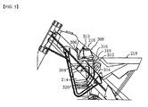
- the motorbike 2000 illustrated in FIG. 4 includes a modified engine 214, a frame 212 and a fuel tank 218, and an enlargement of the relevant parts is illustrated in FIG. 5.
- the engine 214 is a four stroke engine, and a cylinder within the engine is in a state such that a suction assembly 216 and the fluid are connected.
- the engine 214 includes, as a substitution of a carburetor, an electronic injection valve 302. Accordingly, the engine 214 can be vertically disposed such that it extends upwards from an engine frame 234.
- the suction assembly 216 includes a bifurcated housing 304, an air box 306, an air filter 308 and a retainer 310.
- the air filter 308 prevents dust and mud, which damages the engine, from being sucked into the engine, and the engine 214 is disposed below the air filter 308.
- the housing 304 includes an air diverging pipe 312 and a fuel injection valve 314 that attached to the air diverging pipe 312.
- An open end 316 of the air diverging pipe 312 extend upwards to form a flange 318, while the other end 320 of the air diverging pipe 312 is connected to the engine 214.
- the air diverging pipe 312 directs air flow to the housing 304 and towards the engine 214.
- the fuel injection valve 314 receives fuel from the fuel tank 218 and injects the fuel to the air flow within the air diverging pipe 312.
- the air diverging pipe (air inlet) 312 can be connected to the engine 214 without having substantially 90° curve.
- the space for the fuel tank is being oppressed.
- problem such as the capacity of the fuel tank 218 cannot be sufficiently maintained occurs.
- a motorcycle having a main frame and an engine, wherein the main frame is composed of a pair of left-right frame members, and wherein an air inlet extends in a space between the frame members and is connected to the engine in a substantially longitudinally extending line.
- a motorcycle having, as far as possible, substantially straight air inlet, and also having a fuel tank with sufficient capacity.
- the motorcycle further comprises a fuel tank disposed in front of a seat and above the main frame, an air cleaner box disposed below the seat and behind a rear suspension, wherein the engine is provided below the main frame; and the air inlet extending from the air cleaner box is connected to the engine, and wherein when viewed from above the motorcycle, the air inlet extends and is connected to the engine in a straight line.
- the pair of left-right frame members branch from a frame member that extends from a head pipe to the rear.
- the main frame is integrated with left-right bracket rear arms, wherein a cross tube is provided to connect the upper ends of the left-right bracket rear arms to each other, and wherein the cross tube is disposed behind and below a throttle body, which is connected to a part of the air inlet, and supports the upper end of the rear suspension.
- the engine is provided such that a cylinder within the engine is substantially vertical, and wherein an angle at which the air inlet is connected to the engine is between 30° and 60° inclusively, based on a direction in which the cylinder extends.
- the motorcycle has a specification of an off-road motorcycfe.
- the present embodiments described hereinafter are effective to easily improve gas emission performance and engine output, and to enable fuel tank having sufficient capacity to be mounted thereon.
- FIG. 6 is a side view schematically illustrating the structure of a motorcycle 100 in the present embodiment
- FIG. 7 is a plan view illustrating the relevant parts of the motorcycle 100.
- a fuel tank 30 and a seat 10 have been omitted so as to expose a main frame 20.
- the motorcycle 100 in the present embodiment includes the fuel tank 30, an air cleaner box 40, an engine 50 and an air inlet 60.
- the fuel tank 30 is disposed in front of the seat 10 and above the main frame 20; and the air cleaner box 40 is disposed below the seat 10 and behind a rear suspension (rear cushion) 90.
- the engine 50 is disposed below the main frame 20, and the air inlet 60 extends from the air cleaner box 40 to be connected with the engine 50.
- the main frame 20 is composed of a pair of left-right frame members 22, and when viewed from above the motorcycle 100, the air inlet 60 extends and is connected to the engine 50 in a straight line.
- FIG. 8 a perspective view of the structure shown in FIG. 7 is illustrated in FIG. 8.
- the air cleaner box 40 has been omitted in both FIGS. 7 and 8 to provide a clearer view of the interior of the structure.
- FIG. 9 illustrates a side view of the relevant parts with the fuel tank 30 and the air cleaner box 40 being attached and the seat 10 being represented by dotted lines.
- FIG. 9 is a perspective view of the structure illustrated in FIG. 8 with the fuel tank 30 and the seat 10 being mounted thereon
- FIG. 10 is a side view of the relevant parts with the fuel tank 30 being mounted on the structure illustrated in FIG. 8.
- the fuel tank 30 is disposed in front of the seat 10 and above the main frame 20
- the air cleaner box 40 is disposed below the seat 10 and behind the rear suspension 90
- the engine 50 is provided below the main frame 20
- the main frame 20 is composed of a pair of left-right frame members 22.
- the air inlet 60 extends in a straight line from the cleaner box 40 to connect with the engine 50.
- the engine output can be easily increased and a fuel tank having sufficient capacity can also be mounted.
- a suction pipe including a throttle body 62 can be connected smoothly to the air inlet 60, which is in turn connected to the engine 50.
- the throttle body 62 can be disposed in a straight line behind the engine 50 via the straight air inlet 60, the interior of the engine 50 is in symmetry and an even air mixture can be delivered.
- suction setting for cleaning the exhaust gas can be easily performed.
- engine output can also be easily increased because of the straight (when viewed from above) air inlet 60.
- the air cleaner box 40 is disposed below the seat 10 and behind the rear suspension 90, the space for the fuel tank 30 is not being suppressed by the air cleaner box 40, and thus the fuel tank 30 having sufficient capacity can be mounted.
- the air inlet 60 is disposed above the rear suspension 90, a width corresponding to the width A in the structure illustrated in FIG. 2 can be reduced, and maneuverability improved. Also as differs from the structure illustrated in FIG. 2, since a structure (for example, see FIG. 9) in which the exhaust passage 72 is not disposed in the proximity of the rear suspension 90 can be easily adopted, the problem of the suspension being affected by the heat of the exhaust gas can be avoided. Moreover, by utilizing the technique in the present embodiment, the air inlet of the structure illustrated in FIG. 2 can also be substituted by an exhaust passage. Hence design that requires two exhaust passages or an increase in engine performance can also be easily achieved.
- the throttle body 62 is a carburetor of a fuel injection system.
- the throttle body 62 is being used as a carburetor, and the size of the carburetor can be reduced by using the throttle body 62.
- the positions (and capacity) of the fuel tank 30 and the seat 10 (hence, the height H s of the seat) can be maintained, while the position of a cross tube 80 can be located as high as possible under a certain limit. Accordingly, both the desire for reducing the height H B in view of maneuverability and the desire for increasing the minimum height of H L in view of off-road ridding can be satisfied.
- the pair of left-right frame members 22 in the motorcycle 100 do not branch directly from a head pipe 70, but branch from a frame member 21 that extends towards the rear from the head pipe 70.
- the main frame 20 of the present invention can adopt a structure in which the pair of left-right frame members 22 branch directly from the head pipe 70 or a structure illustrated in FIG. 7.
- the following advantages can be achieved by adopting the structure in which the pair of left-right frame members 22 branch from the frame member 21 illustrated in FIG. 7.
- the front wheel 71 might feel wobbling when traveling off road.
- the main frame 20 is made of two left-right frame members 22 directly branched from the head pipe 70, under the same road condition, the wobbling feeling of the front wheel 71 can be eliminated but the rigidity of the vehicle will be relatively reduced.
- the front portion of the main frame 20 is made of one frame member 21 extending from the head pipe 70 and the rear portion of the main frame 20 is made of two left-right branching frame members 22, the advantage of eliminating the wobbling feeling of the front wheel 71 while maintaining the rigidity of the vehicle can be achieved.
- the main frame 20 is formed integrated with left-right bracket rear arms 24, and the upper end of the left-right bracket rear arms 24 are connected to each other via a cross tube 80 (see specifically FIGS. 8 and 9).
- the bracket rear arms 24 are a pair of left-right members that movably supported the front end of the rear arm 92, and connected to the rear end of the pair of left-right main frame 20.
- the bracket rear arms 24 are disposed such that it extends in an up-down direction behind the engine 50, and the rear end of the rear arm 92 supported by the bracket rear arms 24 is pivotally attached by the rear wheel (73).
- the bracket rear arms 24 are integrated with the main frame 20 by welding.
- the cross tube 80 is disposed behind and below the throttle body 62, which is attached to a part of the air inlet 60, and supports the upper end of the rear suspension 90. According to this structure, even if the air inlet 60 passes above the rear suspension 90, the rear suspension 90 can be disposed at a relatively high position. Hence, a relatively long suspension can be used and the decrease in performance of the suspension can be prevented.
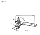
- the link mechanism 95 in the present embodiment is a bottom-link type link mechanism illustrated in FIG. 11.
- the bottom-link type link mechanism 95 enables the cushion to be lowered below the rare arm, and gets near the pivot. Hence the space below the seat 10 can be effectively utilized.
- a pro-link types link mechanism or an on-off link types link mechanism can also be used.
- the level ratio increases when A or C increases, and decreases when B or D increases.
- the length of the arm rely (L) is short, the variation of ⁇ and ⁇ increases, and the variation of the level ratio increases.
- the angle ⁇ between the cushion and the arm rely is typically 40° to 80°, and the angle ⁇ between the arm rely and the arm is typically 70° to 110°.
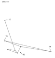
- FIG. 12 is an example of the cushion in the present embodiment in a fully compressed state, and a wheel axle 74 of the rear wheel 73, an upper end 75 of the rear cushion 90, a pivot 76, and the link mechanism 95 are illustrated in the drawing.
- FIG. 13 is an example of the cushion in an uncompressed state.
- a large cushion performance indicated by the arrows can be achieved by the link mechanism.
- FIG. 15 is a side view of the upper portion of the engine 50 with a part being omitted.
- the engine 50 is disposed such that a cylinder 52 within the engine 50 is substantially vertical (for example, ⁇ 15 ⁇ from the vertical line).
- the engine can be mounted at the front.
- the center of gravity of the engine itself can be adjusted to be close to the center of gravity of the entire vehicle. As a result, maneuverability can be improved by disposing heavy load (engine) near the center of gravity.
- the angle ⁇ at which the air inlet 60 (here, a suction port 61 directly connected to the engine) is connected to the engine 50 is based on the extending direction 55 of the cylinder 52, for example within 60° (typically between 30° and 60°).
- the angle ⁇ illustrated in the drawing is 52°.
- the straight and oblique (therefore not perpendicular) suction port 61 is provided instead of an approximately perpendicularly curved suction port. A structure that enables easy increase of engine output can be achieved by avoiding such curving portion.
- the straight air inlet 60 including the throttle body 62 can be connected to the engine 50, an even air mixture can be delivered within the symmetrical engine 50 (cylinder 52) as compared to the structure illustrated in FIG. 3 in which uneven air mixture tends to be delivered.
- suction setting for cleaning the exhaust gas can be easily performed, and engine output easily increased.
- the air cleaner box 40 since the air cleaner box 40 is disposed below the seat 10 and behind the rear suspension 90, the air cleaner box 40 does not oppress the space for the fuel tank 30. As a result, a fuel tank having sufficient capacity can be mounted and problems encountered when using the structure illustrated in FIG. 5 can also be prevented.
- Off-road bike is mainly used as an example in the present embodiment.
- the term “motorcycle” in the present specification includes motorbike and scooter, specifically, vehicle that can be turned by tilting the vehicle body.
- the term “motorcycle” can also includes vehicles of which at least the front or the rear has two or more wheels; or in view of the number of tires, three-wheels vehicle, four-wheels vehicle (or more wheels vehicle).
- the present teaching is also applicable to other vehicles that can utilize the effect of the present invention, for example, apart from motorcycle, the so called saddle ridding vehicles (snowmobile, ATV: all terrain vehicle, etc.).
- a motorcycle having a fuel tank with sufficient capacity mounted thereon and, as far as possible, a straight air inlet, can be provided.
- a motorcycle of the present embodiment including a fuel tank disposed in front of a seat and above a main frame, an air cleaner box disposed below the seat and behind a rear suspension, an engine provided below the main frame; and an air inlet extending from the air cleaner box and is connected to the engine, the main frame is composed of a pair of left-right frame members, and when viewed from above the motorcycle, the air inlet extends and is connected to the engine in a straight line.
- the fuel tank is disposed in front of the seat and above the main frame, the air cleaner box is disposed below the seat and behind the rear suspension, the engine is provided below the main frame, the main frame is composed of a pair of left-right frame members, and the air inlet extends from the air cleaner box and is connected to the engine in a straight line, the engine output can be readily increased and a fuel tank having sufficient capacity can be mounted.
- an air inlet including a throttle body can be provided such that it smoothly connects to the engine, and when viewed from above, a carburetor (throttle body) can be provided behind the engine in a straight line via the straight air inlet.
- a carburetor throttle body
- the interior of the engine is in symmetry and an even air mixture can be delivered, and suction setting for cleaning the exhaust gas can be easily performed.
- the straight air inlet when viewed from above, the engine output can also be easily increased. Since the air cleaner box is disposed below the seat and behind the rear suspension, the air cleaner box does not oppress the space for the fuel tank, and thus a fuel tank having sufficient capacity can be mounted.
- the pair of left-right frame members branch from a frame member that extends from a head pipe to the rear.
- the main frame is integrated with left-right bracket rear arms, a cross tube is provided to connect the upper ends of the left-right bracket rear arms to each other, and the cross tube is disposed behind and below a throttle body, which is connected to a part of the air inlet, and supports the upper end of the rear suspension.
- the engine is provided such that a cylinder within the engine is substantially vertical, and an angle at which the air inlet is connected to the engine is between 30° and 60° inclusively, based on a direction in which the cylinder extends.
- the motorcycle has a specification of an off-road motorcycle.
- a motorcycle 100 including fuel tank 30 disposed in front of seat 10 and above main frame 20, air cleaner box 40 disposed below seat 10 and behind rear suspension 90, engine 50 provided below main frame 20, and air inlet 60 extending from air cleaner box 40 and is connected to engine 50.
- Main frame 20 is composed of a pair of left-right frame members 22, and when viewed from above motorcycle 100, air inlet 60 extends and is connected to engine 50 in a straight line.
Landscapes
- Engineering & Computer Science (AREA)
- Mechanical Engineering (AREA)
- Automatic Cycles, And Cycles In General (AREA)
- Axle Suspensions And Sidecars For Cycles (AREA)
Applications Claiming Priority (1)
| Application Number | Priority Date | Filing Date | Title |
|---|---|---|---|
| JP2005005736A JP2006193026A (ja) | 2005-01-12 | 2005-01-12 | 自動二輪車 |
Publications (1)
| Publication Number | Publication Date |
|---|---|
| EP1681229A2 true EP1681229A2 (de) | 2006-07-19 |
Family
ID=36129962
Family Applications (1)
| Application Number | Title | Priority Date | Filing Date |
|---|---|---|---|
| EP20060000525 Withdrawn EP1681229A2 (de) | 2005-01-12 | 2006-01-11 | Motorrad |
Country Status (2)
| Country | Link |
|---|---|
| EP (1) | EP1681229A2 (de) |
| JP (1) | JP2006193026A (de) |
Cited By (2)
| Publication number | Priority date | Publication date | Assignee | Title |
|---|---|---|---|---|
| EP1923304A3 (de) * | 2006-11-15 | 2008-06-18 | Yamaha Hatsudoki Kabushiki Kaisha | Fahrzeug |
| US8104565B2 (en) * | 2006-11-15 | 2012-01-31 | Yamaha Hatsudoki Kabushiki Kaisha | Body frame and vehicle |
Families Citing this family (3)
| Publication number | Priority date | Publication date | Assignee | Title |
|---|---|---|---|---|
| US8157041B2 (en) | 2007-03-22 | 2012-04-17 | Suzuki Kabushiki Kaisha | Intake device for motorcycle |
| JP5865323B2 (ja) * | 2013-09-30 | 2016-02-17 | 本田技研工業株式会社 | 鞍乗り型車両 |
| JP6175013B2 (ja) * | 2014-02-28 | 2017-08-02 | 本田技研工業株式会社 | 自動二輪車の燃料供給配管配置構造 |
Citations (2)
| Publication number | Priority date | Publication date | Assignee | Title |
|---|---|---|---|---|
| WO1999056997A2 (en) | 1998-05-07 | 1999-11-11 | Cannondale Corporation | Motorcycle, frame, fuel tank and engine |
| JP2001278158A (ja) | 2000-03-31 | 2001-10-10 | Honda Motor Co Ltd | 自動2輪車用車体フレーム |
-
2005
- 2005-01-12 JP JP2005005736A patent/JP2006193026A/ja active Pending
-
2006
- 2006-01-11 EP EP20060000525 patent/EP1681229A2/de not_active Withdrawn
Patent Citations (2)
| Publication number | Priority date | Publication date | Assignee | Title |
|---|---|---|---|---|
| WO1999056997A2 (en) | 1998-05-07 | 1999-11-11 | Cannondale Corporation | Motorcycle, frame, fuel tank and engine |
| JP2001278158A (ja) | 2000-03-31 | 2001-10-10 | Honda Motor Co Ltd | 自動2輪車用車体フレーム |
Cited By (3)
| Publication number | Priority date | Publication date | Assignee | Title |
|---|---|---|---|---|
| EP1923304A3 (de) * | 2006-11-15 | 2008-06-18 | Yamaha Hatsudoki Kabushiki Kaisha | Fahrzeug |
| US8061468B2 (en) | 2006-11-15 | 2011-11-22 | Yamaha Hatsudoki Kabushiki Kaisha | Vehicle |
| US8104565B2 (en) * | 2006-11-15 | 2012-01-31 | Yamaha Hatsudoki Kabushiki Kaisha | Body frame and vehicle |
Also Published As
| Publication number | Publication date |
|---|---|
| JP2006193026A (ja) | 2006-07-27 |
Similar Documents
| Publication | Publication Date | Title |
|---|---|---|
| JP6642837B2 (ja) | 鞍乗り型車両のabs配置構造 | |
| US6371236B1 (en) | Vehicle frame structure of motorcycle | |
| CN101934846B (zh) | 机动二轮车 | |
| JP5014858B2 (ja) | 車体フレーム構造 | |
| US7766119B2 (en) | Vehicle | |
| JP7351250B2 (ja) | 鞍乗型車両 | |
| US20100224172A1 (en) | Evaporated fuel controlling apparatus for all terrain vehicle | |
| US6601666B2 (en) | Motorcycle frame | |
| CN101254818A (zh) | 机动二轮车的发动机悬挂装置 | |
| CN102030063A (zh) | 机动二轮车 | |
| JP2008230492A (ja) | 自動二輪車の燃料供給装置 | |
| EP1681229A2 (de) | Motorrad | |
| ITTO990756A1 (it) | Struutura di cavalletto centrale per motociclette | |
| JP2007137408A (ja) | 鞍乗り型車両 | |
| EP1642811A1 (de) | Einrichtung zum Verstellen eines Windschildes für Fahrzeuge | |
| CN100546866C (zh) | 鞍乘型车辆 | |
| CN103180201B (zh) | 机动二轮车 | |
| JP2012056497A (ja) | 自動二輪車のエアクリーナ構造 | |
| JP2015067247A (ja) | 鞍乗り型車両 | |
| JP4252816B2 (ja) | 自動2輪車の構造 | |
| JP2006306283A (ja) | 自動2輪車の車体構造 | |
| JP3606495B2 (ja) | 自動二輪車の車体フレーム構造 | |
| JPH0515596B2 (de) | ||
| JP2003237671A (ja) | 車両用スイングアーム | |
| JPH1179041A (ja) | 鞍乗り型4輪車 |
Legal Events
| Date | Code | Title | Description |
|---|---|---|---|
| PUAI | Public reference made under article 153(3) epc to a published international application that has entered the european phase |
Free format text: ORIGINAL CODE: 0009012 |
|
| AK | Designated contracting states |
Kind code of ref document: A2 Designated state(s): AT BE BG CH CY CZ DE DK EE ES FI FR GB GR HU IE IS IT LI LT LU LV MC NL PL PT RO SE SI SK TR |
|
| AX | Request for extension of the european patent |
Extension state: AL BA HR MK YU |
|
| STAA | Information on the status of an ep patent application or granted ep patent |
Free format text: STATUS: THE APPLICATION HAS BEEN WITHDRAWN |
|
| 18W | Application withdrawn |
Effective date: 20090804 |