EP1681534A2 - Lasernivelliervorrichtung - Google Patents
Lasernivelliervorrichtung Download PDFInfo
- Publication number
- EP1681534A2 EP1681534A2 EP06100194A EP06100194A EP1681534A2 EP 1681534 A2 EP1681534 A2 EP 1681534A2 EP 06100194 A EP06100194 A EP 06100194A EP 06100194 A EP06100194 A EP 06100194A EP 1681534 A2 EP1681534 A2 EP 1681534A2
- Authority
- EP
- European Patent Office
- Prior art keywords
- housing
- laser
- disposed
- pendulum
- bearings
- Prior art date
- Legal status (The legal status is an assumption and is not a legal conclusion. Google has not performed a legal analysis and makes no representation as to the accuracy of the status listed.)
- Granted
Links
- 230000000712 assembly Effects 0.000 description 11
- 238000000429 assembly Methods 0.000 description 11
- 229910052751 metal Inorganic materials 0.000 description 6
- 239000002184 metal Substances 0.000 description 6
- 229920001971 elastomer Polymers 0.000 description 5
- 230000005484 gravity Effects 0.000 description 5
- -1 Loc-Tite Chemical class 0.000 description 4
- 150000001875 compounds Chemical class 0.000 description 4
- 239000013536 elastomeric material Substances 0.000 description 4
- 239000000463 material Substances 0.000 description 4
- 239000004033 plastic Substances 0.000 description 4
- 229920003023 plastic Polymers 0.000 description 4
- 238000001125 extrusion Methods 0.000 description 3
- 239000003292 glue Substances 0.000 description 3
- 229910001369 Brass Inorganic materials 0.000 description 2
- 229910000831 Steel Inorganic materials 0.000 description 2
- 238000007792 addition Methods 0.000 description 2
- 239000000853 adhesive Substances 0.000 description 2
- 230000001070 adhesive effect Effects 0.000 description 2
- 229910052782 aluminium Inorganic materials 0.000 description 2
- XAGFODPZIPBFFR-UHFFFAOYSA-N aluminium Chemical compound [Al] XAGFODPZIPBFFR-UHFFFAOYSA-N 0.000 description 2
- 239000010951 brass Substances 0.000 description 2
- 239000011521 glass Substances 0.000 description 2
- 230000003287 optical effect Effects 0.000 description 2
- 238000009428 plumbing Methods 0.000 description 2
- 239000010959 steel Substances 0.000 description 2
- 229920002803 thermoplastic polyurethane Polymers 0.000 description 2
- RYGMFSIKBFXOCR-UHFFFAOYSA-N Copper Chemical compound [Cu] RYGMFSIKBFXOCR-UHFFFAOYSA-N 0.000 description 1
- 229920000443 Xenoy Polymers 0.000 description 1
- 230000004075 alteration Effects 0.000 description 1
- 238000010276 construction Methods 0.000 description 1
- 229910052802 copper Inorganic materials 0.000 description 1
- 239000010949 copper Substances 0.000 description 1
- 238000013016 damping Methods 0.000 description 1
- 238000001514 detection method Methods 0.000 description 1
- 238000009434 installation Methods 0.000 description 1
- 230000009916 joint effect Effects 0.000 description 1
- 238000012544 monitoring process Methods 0.000 description 1
- XLYOFNOQVPJJNP-UHFFFAOYSA-N water Substances O XLYOFNOQVPJJNP-UHFFFAOYSA-N 0.000 description 1
Images



Classifications
-
- G—PHYSICS
- G01—MEASURING; TESTING
- G01C—MEASURING DISTANCES, LEVELS OR BEARINGS; SURVEYING; NAVIGATION; GYROSCOPIC INSTRUMENTS; PHOTOGRAMMETRY OR VIDEOGRAMMETRY
- G01C15/00—Surveying instruments or accessories not provided for in groups G01C1/00 - G01C13/00
- G01C15/10—Plumb lines
- G01C15/105—Optical plumbing
-
- G—PHYSICS
- G01—MEASURING; TESTING
- G01C—MEASURING DISTANCES, LEVELS OR BEARINGS; SURVEYING; NAVIGATION; GYROSCOPIC INSTRUMENTS; PHOTOGRAMMETRY OR VIDEOGRAMMETRY
- G01C15/00—Surveying instruments or accessories not provided for in groups G01C1/00 - G01C13/00
- G01C15/002—Active optical surveying means
-
- G—PHYSICS
- G01—MEASURING; TESTING
- G01C—MEASURING DISTANCES, LEVELS OR BEARINGS; SURVEYING; NAVIGATION; GYROSCOPIC INSTRUMENTS; PHOTOGRAMMETRY OR VIDEOGRAMMETRY
- G01C15/00—Surveying instruments or accessories not provided for in groups G01C1/00 - G01C13/00
- G01C15/002—Active optical surveying means
- G01C15/004—Reference lines, planes or sectors
-
- Y—GENERAL TAGGING OF NEW TECHNOLOGICAL DEVELOPMENTS; GENERAL TAGGING OF CROSS-SECTIONAL TECHNOLOGIES SPANNING OVER SEVERAL SECTIONS OF THE IPC; TECHNICAL SUBJECTS COVERED BY FORMER USPC CROSS-REFERENCE ART COLLECTIONS [XRACs] AND DIGESTS
- Y10—TECHNICAL SUBJECTS COVERED BY FORMER USPC
- Y10T—TECHNICAL SUBJECTS COVERED BY FORMER US CLASSIFICATION
- Y10T29/00—Metal working
- Y10T29/49—Method of mechanical manufacture
- Y10T29/49826—Assembling or joining
Definitions
- This invention relates generally to laser levels and more specifically to a laser level which generates a laser line on a surface.
- US Patent No. 5,539,990 which is wholly incorporated herein by reference, disclosesan optical levelling, plumbing and angle-calibrating instrument including a frame, a plumb body universally pendulously mounted on the frame and defining a vertical plumb line gravitationally, at least an illuminator electrically connected to a power supply and mounted on the plumb body for emitting laser light, and at least a cylindrical-surfaced lens mounted on the plumb body in front of the illuminator for planarly diverging the laser light as emitted from the illuminator through the lens to form a laser light plane transverse to a lens axis of the cylindrical-surfaced lens, whereby the laser light plane will projectivety intersect an objective wall to form a straight line of optical image, serving as a reference line for levelling or plumbing use.
- Such laser level may be difficult to install on a wall, etc.
- an improved laser level is employed.
- the laser level has A laser level includes a housing, a pendulum pivotably mounted to the housing and a laser diode assembly disposed on the pendulum.
- a gimbal assembly is employed for pivotably mounting the pendulum to the housing.
- the gimbal assembly includes a frame connected to the housing, a first pair of bearings disposed on the frame, an axle extending through the first pair of bearings, a body disposed on the axle and pivotably supporting the pendulum, and a second pair of bearings disposed between the body and the pendulum.
- the first pair of bearings is disposed on one side of the second pair of bearings.
- FIG. 1 is a perspective view of the laser level according to the invention
- FIG 2 is a partial cross-section of the laser level according to the invention.
- FIG. 3 illustrate a gimbal assembly according to the invention, where FIGS. 3A-3B are top plan views of a first and second embodiment of the gimbal assembly, respativety:
- FIG. 4 illustrates a laser assembly according to the invention, where FIGS. 4A-4B are a partial cross-section and a partial perspective view of the laser assembly, rcspectively,
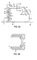
- FIG. 5 illustrates aspects of a housing according to the invention, where FIG. 5A is a side view, and FIG. 5B is a partial cross-sectional view along line B-B of FIG. 5A;
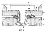
- FIG. 6 is a partial cross-sectional view along line VI-VI of FIG. 5A.
- FIG. 7 illustrates a wall mount assembly according to the invention, where FIG. 7A is a side view, and FIG. 7B is a partial cross-sectional view along line C-C of FIG. 7A.
- a laser level 10 may have a housing 11, a pendulum assembly 20 hung inside the housing II, and two line generating laser assemblies 40 disposed on the pendulum assembly 20.
- Each laser assembly 40 preferably generates a laser light plane so that, upon contact with a surface, such as a wall, a laser line is generated on the surface.
- one of the laser assemblies 40 is aligned so that it generates a horizontal planar beam HP, so that a horizontal line HL appears on the surface.
- the other laser assembly 40 may be aligned to generate a vertical planarheam VP, so that a vertical line VL appears on the surface.
- Horizontal planar beam HP anchor vertical planar beam VP preferably exit housing 11 via a window IS mounted unto housing 11.
- Laser assemblies 40 may be powered by at least one battery 12 mounted in housing 11. Persons skilled in the art will recognize that battery 12 may alternatively be mounted on pendulum assembly 20.
- a switch 13 may connected to battery 12 and the laser assemblies 40 via wires 14. Switch 13 may be used to control whether one or both lasers assemblies 40 are tumed on, thus projecting horizontal and/or vertical lines unto the surface.
- Pendulum assembly 20 may include a pendulum body 21, which supports the laser assemblies 40.
- Pendulum body 21 is preferably made of a nonferrous material, such as cast aluminum.
- pendulum assembly 20 may be pivotally mounted to the housing 11 via gimbal assembly 30.
- a first embodiment of the gimbal assembly 30 is shown in FIG. 3A.
- Such assembly 30 may include a frame 31 attached to the housing 11. At least one and preferably two bearings 32 may be rotatably disposed on the frame 31. An axle 34 may be supported by the bearing(s) 32. Gimbal body 35 may be disposed on and rotate with axle 34.
- Gimbal body 35 may have pins 37 extending outwardly.
- Pendulum body 21 may be rotationally connected to the pins 37 via at least one and preferably two bearings 36.
- the bearing(s) 32 may be disposed on axle 34, whereas the bearing(s) 36 can be disposed on the pins 37.
- pins 37 may be replaced with a unitary pin or axle.
- pins 37 are coaxial and substantially perpendicular to axle 34.
- the axes of pins 37 and axle 34 preferably intersect at a point over the center of gravity CG of pendulum body 21.
- a shorter gimbal assembly 30 may also allow the vertical laser assembly 40 to project the vertical planar beam VP (and thus vertical line VL) that extends behind axle 37, as shown in FIG. 2.
- the shoner gimbal assembly 30 may allow the vertical laser assembly 40 to project the vertical planar beam VP (and thus vertical line VL) that extends behind the center of gravity CG of pendulum body 21.
- Such arrangement increases the visibility of the vertical line VL on a ceiling above a user's head.
- Gimbal body 35 may have a slot 35S to allow vertical planar beam VP to project through gimbal body 35 and/or through the axis of pins 37.
- the gimbal assembly 30 preferably has a pair of bearings (e.g., bearings 32) not disposed between the other pair of bearings (e.g.. bearings 36).
- a pair of bearings e.g., bearings 32
- FIG. 3B An alternate embodiment of gimbal assembly 30 may be seen in FIG. 3B. where like parts refer to like numerals.
- gimbal body 35 is no longer substantially between bearings 36. Instead, gimbal body 35 preferably extends sideways and supports bearings 36.
- Pendulum body 21 in turn may have an axle 38, which is pivotably supported by bearings 36.
- the axes of axles 34, 38 substantially perpendicular, and that at least one pair of bearings is not disposed between the other pair of bearings.
- the center of gravity CG may be coplanar with the rotational axis of with axle 38, and that center of gravity CG may not need to be directly underneath the intersection of the axes of axles 34, 38.
- pendulum body 21 may threadingly receive at least one set screw 23 to ensure the proper balancing of the pendulum assembly 20.
- set screw 23 would be rotated to provide the proper balance, and then fixed in position with a locking compound, such as Loc-Tite, etc.
- Set screw 23 may support one or more nuts 23N threadingly disposed thereon to further ensure the proper balancing of the pendulum assembly 20.
- Pendulum body 21 may also have a bottom plate 22.
- Bottom plate 22 may be made of copper.
- a rubber piece or O-ring 220 may be provided on the bottom plate 22 or elsewhere on the pendulum body 21 (such as rubber piece or O-ring 240) to deaden any vibrating, and thus limit ranling of the pendulum assembly 20.
- Bottom plate 22 may magnetically interact with a magnet 15 disposed in housing 1 1 for magnetically damping pendulum assembly 20, as is well known in the art.
- Pendulum body 21 may have a laser barrel 25 for holding each laser assemblies 40. As shown in FIG. 2, the laser barrels 25 (and thus laser assemblies 40) are preferably disposed side-by-side, rather than one arranged on the top of the other. Such arrangement reduces the height of the pendulum body 21 and/or of the laser level 10.
- the axes of the laser barrels 25 are preferably neither parallel nor coplanar.
- the laser barrel 25 supporting the vertical laser assembly 40 is preferably inclined relative to the laser barrel 25 supporting the horizontal laser assembly 40.
- the laser barrel 25 supporting the vertical laser assembly 40 is preferably inclined upwardly at an angle of about 40 degrees from a horizontal line.
- the laser assemblies 40 may be assembled as follows. First, a laser diode 41 is inserted into one side of laser barrel 25. The laser diode 41 may be affixed to laser barrel 25 via a press fit, glue, a locking compound (such as Loc-Tite), a cap, or a set screw, etc.
- a locking compound such as Loc-Tite
- a collimating lens holder 42 supporting collimating lens 42L is inserted into the other side of laser barrel 25.
- Collimating lens holder 42 may be made of aluminum.
- Collimating lens holder 42 may be affixed to laser barrel 25 via glue, a locking compound (such as Loc-Tite), a cap, or a set screw, etc.
- a line or cylindrical lens 43 is preferably inserted into a lens holder 44.
- the lens holder 44 is then pivotally attached to barrel connector 45 via a pin 46.
- the barrel connector 45 is then disposed on laser barrel 25.
- Lens holder 44 and/or barrel connector 45 may be made of brass.
- the lens holder 44 is preferably rotated about pin 46 to eliminate line crowning.
- the lens holder 44 is then glued in place unto barrel connector 45.
- the barrel connector 45 is then rotated about its longitudinal axis to the appropriate orientation.
- the barrel connector 45 is then glued in place to laser barrel 25.
- a locking compound such as Loc-Tite, etc., may be used fix the position of lens holder 44 and/or barrel connector 45.
- Such arrangement allows for adjustment along two axes with a minimal number of components. Such arrangement may also ensure that the lens holder 44 and/or barrel connector 45 maintain constant clearance gaps within the assembly to provide optimal and consistent glue joint properties. Furthermore, such assembly does not necessitate any adjustment screws or springs.
- window 15 may be mounted to housing 11 to allow the laser beams to exit housing 11.
- window 15 is preferably made of glass. It is preferable to mount such window 15 to housing I t in a way that protects against breakage and also avoids the quality issues associated with adhesive mounting.
- Window 15 may be mounted to housing 11 by overmolding the two components with a layer 16 of compliant elastomeric material disposed on housing 11.
- a layer 16 of compliant elastomeric material disposed on housing 11.
- Such material may be a thermoplastic urethane, such as Vasollan.
- Housing 11 is preferably is made of plastic, such as Xenoy.
- layer 16 supports window 15 on the front and rear sides thereof.
- Such mounting arrangement preferably results in a complete seal that is free of messy adhesive.
- Such seal may also be waterproof or water resistant.
- the mounting arrangement has natural flexural properties, which may protect window 15 if laser level 10 is dropped or impacted.
- window 15 is disposed at an angle relative to a horizontal line.
- window 15 is disposed at an angle W of such horizontal line.
- angle W is about 55 degrees.
- angle W is preferably larger than angle A.
- housing 11 it is preferable to substantially cover housing 11 with the same elastomeric material of layer 16.
- layer 16 may provide other features, such as feet 11F disposed at the bottom ofhousing 11. Due to the qualities of such material, feet 11 F may provide an anti-skid function in addition to stably supporting the housing 11.
- housing 11 and/or layer 16 may have indicia III thereon to indicate to the user the typical position of vertical line VL and/or horizontal line HL relative to housing 11.
- laser level 10 with a pendulum detecting mechanism 50 to detect when the housing 11 is is tilted beyond a self leveling range, i.e., where the pendulum body 21 is not be able to move to a substantially vertical position in order to generate a truly horizontal and/or vertical line.
- Detecting mechanism 50 may include at least three (and preferably four) pairs 51 of infrared (IR) transmitters 5 1T and receivers 51R.
- the pairs 51 are disposed equidistantly from pendulum body 21, and to each other.
- transmitter 51T is preferably disposed above receiver 51 R or vice versa.
- a gap exists between transmitter 51T and receiver 51 R allowing plate 22 to extend therebetween and interrupt the IR beam.
- a circuit monitoring the pairs 51 enables an out-of-range signal.
- a microprocessor intermittently turns the laser assemblies 40 on and off in order to indicate such situation.
- transmitter/receiver pairs 51 may be disposed in such positions where the plate 22 extends between a pair (thus triggering the out-of-range signal) before the pendulum body 21 contacts the housing 11 or any other component thereof Such arrangement provides for more accurate detection of the out-of-self-leveling-range situation.
- Rubber bumpers 52 may be disposed near the transmitter/receiver pairs 51 to limit the range of movement of the plate 22 (and thus of pendulum body 21).
- laser level 10 may have a pivotable mount assembly 60 pivotably attached to housing II.
- Mount assembly 60 may include a substantially vertical body 61 disposed relatively close to housing 11, and a substantially horizontal flange 62 extending from body 61 and pivotably engaging housing 11.
- flange 62 is disposed above housing 11.
- flange 62 is disposed above housing 11, and the lowest portion of body 61 is disposed above a plane I I P containing the lowest points of housing I 1 (creating a gap G therebetween), the user will be able to dispose the laser level 10 on a horizontal surface without removing mount assembly 60.
- body 61 relatively close to housing 11 minimizes the size of laser level 10. In addition, such placement could prevent damage to body 61 if laser level 10 is dropped, as body 61 does not have a lot of room to bend.
- Body 61 may have at least one magnet 63 and preferably two magnets 63 thereon.
- magnet(s) 63 allow the user to mount laser level 10 to a metal surface or rail. If multiple magnets 63 are used, t is preferable that the polarities of magnets 63 are not aligned.
- a top magnet 63 may be disposed so that its north and south poles are directed towards the rear and front of body 61, respectively, while a bottom magnet 63 may be disposed so that its north and south poles are directed towards the front and rear ofbody 61, respectively. Otherwise, the magnetic fields could affect the level position of pendulum body 21.
- Magnet(s) 63 may be insert molded in body 61.
- a metal plate 64 in body 61 between the magnet(s) 63 to conduct or shunt the magnetic field therebetween, thus minimizing the magnetic disturbance to pendulum body 21.
- Plate 64 may be insert molded in body 61.
- feet 61R on the rear of body 61 to separate body 61 (and more specifically magnet(s) 63) from the metal surface. Such gap will allow the user to easily move laser level 10 along the metal surface.
- Such feet 61F may be made of rubber. Such material would increase friction between the metal surface and laser level 10.
- mount assembly 60 is permanently attached to housing 11. Permanently attaching mount assembly 60 to housing 11 ensures that the user does not lose the mount assembly 60 after detaching it.
- Mount assembly 60 can be attached to housing I I via a screw 67 threadingly 5 engaging housing 11.
- Screw 67 may be made of steel.
- screw 67 may be threadingly engaged to an insert 17 disposed on housing 11.
- Insert 17 may be made of brass. Screw 67 may extend through a hole in flange 62.
- a washer 68 may be disposed between screw 67 and flange 62.
- Washer 68 is preferably made of plastic. Persons skilled in the art will know to select a plastic to ensure low friction between screw 67 and flange 62.
- a washer 69W may be disposed between flange 62 and housing 11. Persons skilled in the art will know to select a plastic to ensure low friction between housing 11 and flange 62. A couple of Belleville washers 69B may be disposed between housing 11 and washer 69W. Such arrangement will take up any play between flange 62 and housing 11. Persons skilled in the art will recognize that such arrangement may also ensure that a constant force exists between flange 62 and housing 11. Such constant force allows for smooth rotation of the housing 11 relative to mount assembly 60.
- Layer 18 maybe an elastomeric material such as a thermoplastic urethane or Versollan.
- Body 61 may have a notch 61N aligned to indicia 111 to indicate to the user the typical position of horizontal line HL relative to housing II and/or body 61.
- Body 61 may have a key hole 65 for hanging laser level from a nail or screw in a wall or reference surface.
- Body 61 and/or flange 62 may have a hole 66 that can receive a wire or rope for tying laser level 10 to a feature to prevent any possible falls.
- laser level 10 may be disposed on a wall mount assembly 70.
- Wall mount assembly 70 may include a body 71, an upper flange 71FU, and a lower flange 71FL.
- body 71 is substantially vertical, whereas upper and lower flanges 71FU, 71FL are preferably substantially horizontal.
- Upper and lower flanges 71FU, 71FL preferably have respective surfaces 71FUS, 71FLS that are substantially coplanar and preferably substantially vertical, so that wall mount assembly 70 can be stably disposed against a wall WW.
- Upper flange 71FU may also have a hole 71 H for allowing a screw or nail 73 to extend therethrough to affix wall mount assembly 70 to watt WW.
- Wall mount assembly 70 may have a metal plate 72 disposed in body 71.
- plate 72 is made of steel.
- Plate 72 may be insert molded in body 71. With such construction, the user need onlyplace mount assembly 60 against body 71 for installation, as magnet(s) 63 will magnetically engage plate 72.
- the user can easily move the laser level 10 relative to wall mount assembly 70 by sliding laser level 10 up or down along axis V.
- Such gap can be created by providing body 61 with protrusions or flanges 61 F extending outwardly from body 61. As shown in FIG. 7B, flanges 61 F contact body 71 and prevent direct contact between plate 72 and magnet(s) 63.
- flanges 61 F contact body 71 and prevent direct contact between plate 72 and magnet(s) 63.
- it is preferable to design flanges 61 so that feet 61 R do not contact plate 72.
- Body 71 may also have protrusions 718 As laser level 10 is moved upwardly or downwardly along body 71, such protrusions 718 would contact a feature of mount assembly 60 (such as flanges 61F) to prevent the user from moving laser level 10 beyond such protrusions. Such protrusions 718 also prevent laser level 10 from sliding off body 71.
- Wall mount assembly 70 may have a clamp 74 pivotably attached to body 7 1 about an axis 74A.
- Clamp 74 may have a spring 75 biasing the clamp 74 towards a surface of wall mount assembly 70, such as lower flange 71FL, for pinching a ceiling rail or extrusion therebetween, thus clamping wall mount assembly 70 to such ceiling rail, extrusion, etc.
- clamp 74 and/or the other surface of wall mount assembly 70, such as lower flange 71FL may have a rubber foot 75 in the clamping area to better grip the extrusion.
- the user can move clamp 74 to release wall mount assembly 70 by rotating clamp 74 about axis 74A by pushing on handle 74H.
- wall mount assembly 70 can be mounted in a first orientation where upper flange 71FU is above lower flange 71FL and a second orientation where upper flange 71FU is below lower flange 71FL.
Landscapes
- Physics & Mathematics (AREA)
- Engineering & Computer Science (AREA)
- General Physics & Mathematics (AREA)
- Radar, Positioning & Navigation (AREA)
- Remote Sensing (AREA)
- Lasers (AREA)
- Semiconductor Lasers (AREA)
- Laser Surgery Devices (AREA)
- Motorcycle And Bicycle Frame (AREA)
- Optical Head (AREA)
Priority Applications (1)
| Application Number | Priority Date | Filing Date | Title |
|---|---|---|---|
| PL06100194T PL1681534T3 (pl) | 2005-01-13 | 2006-01-10 | Poziomnica laserowa |
Applications Claiming Priority (1)
| Application Number | Priority Date | Filing Date | Title |
|---|---|---|---|
| US11/034,696 US7134211B2 (en) | 2004-03-18 | 2005-01-13 | Laser level |
Publications (3)
| Publication Number | Publication Date |
|---|---|
| EP1681534A2 true EP1681534A2 (de) | 2006-07-19 |
| EP1681534A3 EP1681534A3 (de) | 2006-07-26 |
| EP1681534B1 EP1681534B1 (de) | 2008-03-12 |
Family
ID=36097212
Family Applications (1)
| Application Number | Title | Priority Date | Filing Date |
|---|---|---|---|
| EP06100194A Expired - Lifetime EP1681534B1 (de) | 2005-01-13 | 2006-01-10 | Lasernivelliervorrichtung |
Country Status (8)
| Country | Link |
|---|---|
| US (3) | US7134211B2 (de) |
| EP (1) | EP1681534B1 (de) |
| CN (1) | CN1808064A (de) |
| AT (1) | ATE389162T1 (de) |
| DE (1) | DE602006000651T2 (de) |
| DK (1) | DK1681534T3 (de) |
| ES (1) | ES2302293T3 (de) |
| PL (1) | PL1681534T3 (de) |
Cited By (2)
| Publication number | Priority date | Publication date | Assignee | Title |
|---|---|---|---|---|
| WO2008119583A1 (de) * | 2007-03-29 | 2008-10-09 | Robert Bosch Gmbh | Markierungseinrichtung, markierungssystem sowie handhabungsverfahren für ein markierungssystem |
| ITMO20130316A1 (it) * | 2013-11-18 | 2015-05-19 | Simone Ranzini | Attrezzatura per il supporto di livelle laser e simili. |
Families Citing this family (66)
| Publication number | Priority date | Publication date | Assignee | Title |
|---|---|---|---|---|
| US6606798B2 (en) | 2001-02-23 | 2003-08-19 | Black & Decker Inc. | Laser level |
| US7523558B2 (en) * | 2002-10-22 | 2009-04-28 | Black And Decker | Tool incorporating a light line generating device |
| US7513052B2 (en) * | 2002-10-22 | 2009-04-07 | Black And Decker | Light line generating device |
| US7134211B2 (en) * | 2004-03-18 | 2006-11-14 | Black & Decker Inc. | Laser level |
| US7178250B2 (en) * | 2004-07-21 | 2007-02-20 | Irwin Industrial Tool Company | Intersecting laser line generating device |
| TWI311391B (en) * | 2005-04-08 | 2009-06-21 | Quarton Inc | Laser module for projecting a linear laser beam |
| DE102005000140A1 (de) * | 2005-10-17 | 2007-04-19 | Hilti Ag | Neigungssteuerungsverfahren |
| JP4920286B2 (ja) * | 2006-04-03 | 2012-04-18 | 株式会社マイゾックス | レーザー墨出し器 |
| US7497018B2 (en) | 2006-05-26 | 2009-03-03 | William Hersey | Laser-based alignment tool |
| DE102006000359A1 (de) * | 2006-07-20 | 2008-01-24 | Hilti Ag | Handhabbarer selbstnivellierender Laserstrahler mit Lotstrahl |
| US7454839B2 (en) * | 2006-08-22 | 2008-11-25 | Robotoolz, Ltd. | Portable reference laser unit and attachment accessory |
| US20080052926A1 (en) * | 2006-09-05 | 2008-03-06 | Eastway Fair Company Limited | Gravity dial level indicator for line generator |
| USD567685S1 (en) * | 2006-09-29 | 2008-04-29 | Leica Geosystems, Ag | Line laser device |
| EP1925250A1 (de) * | 2006-11-23 | 2008-05-28 | Electrolux Home Products N.V. | Geschirrspülmaschine mit einer Alarmvorrichtung |
| US7363716B1 (en) | 2006-12-13 | 2008-04-29 | Amanda Tonkinson | Image projection and laser level device for layout design of wall-mounted items |
| USD571237S1 (en) * | 2006-12-20 | 2008-06-17 | Pls-Pacific Laser Systems, Llc | Laser level detector |
| DE202007001753U1 (de) * | 2006-12-29 | 2007-06-06 | STABILA Messgeräte Gustav Ullrich GmbH | Messgerät |
| US7784192B2 (en) * | 2007-01-18 | 2010-08-31 | L-3 Insight Technology Incorporated | SWIR vision and illumination devices |
| US8104186B2 (en) | 2007-05-07 | 2012-01-31 | Michael Raschella | Method and system for projecting an aiming X-shaped mark on a target |
| US20080276473A1 (en) * | 2007-05-07 | 2008-11-13 | Michael Raschella | Method of projecting zero-convergence aiming beam on a target and zero-convergence laser aiming system |
| US8011105B2 (en) * | 2007-11-02 | 2011-09-06 | Robert Bosch Tool Corporation | Green beam laser level device |
| US7770296B2 (en) * | 2007-12-06 | 2010-08-10 | Brauch Richard L | Optical system and method of centering a tree within a tree spade |
| DE102007055746A1 (de) * | 2007-12-10 | 2009-06-18 | Hilti Aktiengesellschaft | Optomechanisches Nivelliergerät |
| US7571546B1 (en) * | 2008-02-01 | 2009-08-11 | Black And Decker | Light line generating device |
| US8269612B2 (en) | 2008-07-10 | 2012-09-18 | Black & Decker Inc. | Communication protocol for remotely controlled laser devices |
| DE102009002771A1 (de) * | 2009-04-30 | 2010-11-11 | Hilti Aktiengesellschaft | Lasergerät mit einer justierbaren Pendeleinrichtung |
| DE102009002756B3 (de) * | 2009-04-30 | 2010-07-29 | Hilti Aktiengesellschaft | Haltevorrichtung zur Befestigung eines Lasergerätes |
| CN101782403B (zh) * | 2010-03-09 | 2011-11-30 | 武汉方寸科技有限公司 | 基于线阵ccd的激光投线仪数字化检测装置 |
| US8307562B2 (en) * | 2010-04-29 | 2012-11-13 | Black & Decker Inc. | Laser line generator having three intersecting light planes |
| US8245410B1 (en) * | 2010-11-18 | 2012-08-21 | The Boeing Company | Virtual cutting tool projection device used with cutting tools |
| US8302319B1 (en) * | 2011-06-13 | 2012-11-06 | International Business Machines Corporation | Method and apparatus for aligning and leveling a server rack rail |
| FR2977038B1 (fr) * | 2011-06-23 | 2013-07-26 | Agatec | Procede de montage d'une lentille de collimation dans un dispositif laser |
| USD684646S1 (en) * | 2011-07-13 | 2013-06-18 | Raúl Delgado Acarreta | Magnetic level gauge for ammunition in firearms |
| US11067385B2 (en) * | 2012-01-04 | 2021-07-20 | Chris Olexa | Laser centering tool |
| US9908182B2 (en) | 2012-01-30 | 2018-03-06 | Black & Decker Inc. | Remote programming of a power tool |
| CN104364609B (zh) * | 2012-02-17 | 2017-02-22 | 罗伯特·博世有限公司香港 | 多功能激光标线仪 |
| US20130327552A1 (en) | 2012-06-08 | 2013-12-12 | Black & Decker Inc. | Power tool having multiple operating modes |
| US9170099B2 (en) * | 2012-12-21 | 2015-10-27 | Maquinaria Geka, S.A. | Laser positioner for punching machines |
| US9838586B2 (en) * | 2013-01-31 | 2017-12-05 | Cognex Corporation | Portable apparatus for use in machine vision |
| US9441967B2 (en) | 2013-05-31 | 2016-09-13 | Stanley Black & Decker Inc. | Laser level system |
| EP2840355A1 (de) | 2013-08-21 | 2015-02-25 | HILTI Aktiengesellschaft | Lasergerät und Haltevorrichtung zur Befestigung eines Lasergerätes an einem Halteelement |
| US20150098216A1 (en) * | 2013-10-09 | 2015-04-09 | United Sciences, Llc | Fan Light Element |
| US9303990B2 (en) | 2014-04-11 | 2016-04-05 | Black & Decker Inc. | Laser line generating device |
| US10184218B1 (en) * | 2014-06-10 | 2019-01-22 | Mark Belloni | Marker light |
| DE102014218210A1 (de) * | 2014-09-11 | 2016-03-17 | Robert Bosch Gmbh | Verfahren zur Montierung einer Pendellaservorrichtung |
| DE102014218185B4 (de) | 2014-09-11 | 2019-06-19 | Robert Bosch Gmbh | Verfahren zur Montierung einer Pendellaservorrichtung |
| USD766757S1 (en) * | 2015-03-19 | 2016-09-20 | Black & Decker Inc. | Laser tool |
| USD767419S1 (en) * | 2015-03-19 | 2016-09-27 | Black & Decker Inc. | Laser tool |
| US10363614B2 (en) | 2015-04-02 | 2019-07-30 | Stanley Black & Decker Inc. | Laser level, battery pack and system |
| CN105115523A (zh) * | 2015-09-26 | 2015-12-02 | 陈卡丹 | 一种新型道路工程测量仪器校验装置 |
| DE202016101184U1 (de) * | 2016-03-04 | 2016-03-16 | UMAREX GmbH & Co. KG | Haltevorrichtung für ein Lasergerät |
| US10006768B2 (en) | 2016-03-15 | 2018-06-26 | Stanley Black & Decker Inc. | Laser level |
| CN108731632B (zh) * | 2017-04-20 | 2022-02-25 | 罗伯特·博世有限公司 | 激光水准仪 |
| CN108801228A (zh) * | 2018-06-13 | 2018-11-13 | 沈际明 | 激光水平仪 |
| US11885642B2 (en) * | 2018-09-12 | 2024-01-30 | Robert Bosch Gmbh | Laser leveling tool with gesture control |
| US11320264B2 (en) * | 2018-10-10 | 2022-05-03 | Joeseph Samuel Melton | Laser plumb bob and level aid |
| CN116625331A (zh) | 2019-01-16 | 2023-08-22 | 米沃奇电动工具公司 | 激光投射装置和用于激光投射装置的框架 |
| US11385055B2 (en) | 2019-07-23 | 2022-07-12 | Milwaukee Electric Tool Corporation | Laser emitter with a modular storage unit |
| US11296646B2 (en) | 2020-09-02 | 2022-04-05 | Andrew Pindzola | Alignment device |
| GB202014590D0 (en) | 2020-09-16 | 2020-10-28 | Stanley Works Israel | Laser tool and system |
| WO2022109793A1 (zh) * | 2020-11-24 | 2022-06-02 | 罗伯特·博世有限公司 | 激光校准装置及其调节方法 |
| US12427645B2 (en) | 2021-02-25 | 2025-09-30 | Brian Baggott | Apparatus, system and methodology for identifying site locations within a construction environment |
| USD1026688S1 (en) | 2022-07-21 | 2024-05-14 | Johnson Level & Tool Mfg. Co., Inc. | Line-type laser level |
| USD1060065S1 (en) | 2022-07-21 | 2025-02-04 | Hultafors Group North America, Inc. | Dot-type laser level |
| US20250210925A1 (en) * | 2023-12-20 | 2025-06-26 | Robert Bosch Gmbh | Mount for a Measuring Device |
| EP4579183A1 (de) * | 2023-12-31 | 2025-07-02 | Hilti Aktiengesellschaft | Lasernivelliervorrichtung mit verbessertem stossschutz |
Citations (1)
| Publication number | Priority date | Publication date | Assignee | Title |
|---|---|---|---|---|
| US5539990A (en) | 1995-05-30 | 1996-07-30 | Le; Mike | Three-dimensional optical levelling, plumbing and angle-calibrating instrument |
Family Cites Families (85)
| Publication number | Priority date | Publication date | Assignee | Title |
|---|---|---|---|---|
| US391516A (en) * | 1888-10-23 | Apparatus for drying matrices and casting stereotypes | ||
| US2103184A (en) | 1936-04-06 | 1937-12-21 | Roggero Carlo | Leveling and squaring device |
| US3241243A (en) | 1963-06-20 | 1966-03-22 | Coleman Engineering Company In | Hole center locating apparatus |
| DE1448598C3 (de) | 1963-07-15 | 1973-11-22 | Askania Gmbh, 1000 Berlin | Vorrichtung mit einem Vertikal pendel Neigungsmesser |
| US3238831A (en) | 1964-04-09 | 1966-03-08 | Goodrich Co B F | Fabric trimmer |
| GB1349438A (en) | 1971-12-07 | 1974-04-03 | Hartley Lw | Builders level |
| US3911588A (en) * | 1972-05-27 | 1975-10-14 | Minolta Camera Kk | Optical marker |
| US3911516A (en) | 1974-07-16 | 1975-10-14 | Coats & Clark | Method of forming a push pin article |
| US4031629A (en) | 1976-03-30 | 1977-06-28 | George Paluck | Apparatus for establishing a level plane |
| US4106207A (en) * | 1976-08-09 | 1978-08-15 | Vernon Hugo Boyett | Point to point self-leveling plumbing device |
| FR2531053A1 (fr) | 1982-07-28 | 1984-02-03 | Bennes Marrel | Dispositif detecteur de devers, notamment pour la securite sur une grue, un camion ou analogue |
| DE3409990A1 (de) | 1984-03-19 | 1984-07-12 | Hermann 4905 Spenge Dröge | Vorrichtung fuer einen absenkbaren oberschrank |
| SU1461377A3 (ru) | 1984-05-25 | 1989-02-23 | Рка Корпорейшн (Фирма) | Цветной кинескоп |
| US5243398A (en) | 1991-02-15 | 1993-09-07 | Laser Alignment, Inc. | Surveying instrument including low power light plane generator |
| US5220460A (en) | 1991-09-24 | 1993-06-15 | Eastman Kodak Company | Adjustable mount for cylindrical lens with torque applied directly to lens |
| WO1993022619A1 (en) | 1992-04-27 | 1993-11-11 | Verticalign Aust Pty. Ltd. | Vertical alignment apparatus |
| US5459932A (en) | 1993-08-27 | 1995-10-24 | Levelite Technology, Inc. | Automatic level and plumb tool |
| US5552886A (en) * | 1994-03-01 | 1996-09-03 | Nikon Corporation | Laser beam transmitting apparatus |
| US5500987A (en) | 1994-05-20 | 1996-03-26 | Flotool International, Inc. | Pin clip |
| DE9408464U1 (de) | 1994-05-21 | 1994-07-28 | Becher, Frank, 56072 Koblenz | Vorrichtung zur Anordnung einer Kamera an einem Bohrmaschinenständer |
| JP2808249B2 (ja) | 1994-11-10 | 1998-10-08 | 日本コントロール工業株式会社 | カメラスタンド |
| US5537205A (en) * | 1994-11-15 | 1996-07-16 | Costa; George J. | Self leveling laser plumb assembly |
| DE9418591U1 (de) | 1994-11-21 | 1995-02-16 | M. Hensoldt und Söhne Wetzlar Optische Werke AG, 35576 Wetzlar | Mit einem Laserstrahl arbeitendes Nivelliergerät |
| US5552888A (en) * | 1994-12-02 | 1996-09-03 | Nikon Precision, Inc. | Apparatus for measuring position of an X-Y stage |
| US5531031A (en) * | 1995-01-20 | 1996-07-02 | Green; Kevin D. | Laser level and square |
| IT1275249B (it) * | 1995-02-22 | 1997-07-31 | Micro Italiana Spa | Dispositivo proiettore di uno o piu' fasci piani di raggi laser divergenti autolivellante a gravita' per la proiezione di una o piu' rette orizzontali e/o verticali su corpi del tipo parete o simili |
| JP2900131B2 (ja) | 1995-03-30 | 1999-06-02 | ニッショー機器株式会社 | レーザー光放射装置 |
| US5816692A (en) * | 1995-06-28 | 1998-10-06 | Spectronics Corporation | Compact high-intensity UVA inspection lamp |
| US5644850A (en) | 1995-10-16 | 1997-07-08 | Costales; Straf G. | Laser plumb device |
| US5853241A (en) * | 1995-10-16 | 1998-12-29 | Streamlight, Inc. | Convertible flashlight |
| US5642972A (en) | 1995-11-06 | 1997-07-01 | Southco, Inc. | One-direction captive screw fastener |
| US5644425A (en) * | 1995-11-14 | 1997-07-01 | Itt Corporation | Night Vision Monocular with unistructural optical bed |
| CH691708A5 (de) | 1995-12-29 | 2001-09-14 | Ammann Lasertechnik | Laserstrahl-Nivelliergerät. |
| JPH09210687A (ja) | 1996-01-31 | 1997-08-12 | Topcon Corp | レーザレベル装置 |
| US5903345A (en) | 1996-03-01 | 1999-05-11 | Dwbh Ventures Ltd. | Remotely positionable gravity oriented laser scanner |
| EP0819911B1 (de) | 1996-07-15 | 2002-06-12 | Tai Tsu Opto Technology Co., Ltd. | Optisches Nivellier- und Lotinstrument |
| NO303097B1 (no) | 1996-10-02 | 1998-05-25 | Christian Vonholm | FremgangsmÕte for pÕf÷ring av informasjon/reklame pÕ et transportbÕnd |
| US5864956A (en) | 1996-11-22 | 1999-02-02 | Dong; Dawei | Level line and limb line combination |
| US6105794A (en) | 1997-05-22 | 2000-08-22 | Bauer; George E. | Adjustable support bracket that slides and adjusts within a channel |
| FR2763676B1 (fr) | 1997-05-23 | 1999-07-23 | Lasertec International | Dispositif de positionnement a laser creant un faisceau de repere servant a positionner un sujet ou un objet dans le domaine medical ou industriel |
| US5992029A (en) | 1997-08-14 | 1999-11-30 | Dong; Dawei | Automatic laser plumb line |
| US5983510A (en) | 1997-08-26 | 1999-11-16 | Wu; Chyi-Yiing | Three-dimensional laser levelling and angle-calibrating instrument with multiple functions |
| US5912733A (en) * | 1997-11-05 | 1999-06-15 | Dunlop; Ronald | Laser plumb line |
| AU2217999A (en) | 1998-01-08 | 1999-07-26 | Paul Akers | Laser levelling system, apparatus and method for building construction |
| US6014211A (en) | 1998-01-20 | 2000-01-11 | Laser Reference | Device and method for providing a laser level plane |
| US6177987B1 (en) | 1998-02-26 | 2001-01-23 | Chih-Yu Ting | Laser level |
| DE19810447A1 (de) | 1998-03-11 | 1999-09-16 | Hilti Ag | Aufhängung für eine schwerkraftbeeinflusste Messeinrichtung |
| US6062525A (en) * | 1998-03-18 | 2000-05-16 | Lemire; Robert | Picture frame hanger |
| JP2002511553A (ja) | 1998-04-14 | 2002-04-16 | サウスコ,インコーポレイティド | キャプティブスクリュー |
| US6003825A (en) | 1998-05-27 | 1999-12-21 | Abernathy, Jr.; Henry H. | Adjustable wall hanging device |
| CN2336327Y (zh) * | 1998-06-19 | 1999-09-01 | 陆建红 | 可自动调平的激光标线仪 |
| US6360446B1 (en) * | 1998-08-14 | 2002-03-26 | The Stanley Works | Level having a laser beam source |
| US6028665A (en) | 1998-09-09 | 2000-02-22 | Mcqueen; John | Self-leveling laser plumb |
| US6069748A (en) | 1998-10-20 | 2000-05-30 | Eastman Kodak Company | Laser line generator system |
| IT1307666B1 (it) * | 1999-02-03 | 2001-11-14 | Micro Italiana Spa | Dispositivo portatile autolivellante a raggio laser,perfezionato |
| DE19952390A1 (de) | 1999-10-29 | 2001-05-03 | Hilti Ag | Rotationsbaulaser |
| US6182916B1 (en) * | 1999-11-12 | 2001-02-06 | Index Measuring Tape Co., Ltd. | Measuring tape dispenser with an impact buffer housing and tentative tape halting means |
| US6606798B2 (en) | 2001-02-23 | 2003-08-19 | Black & Decker Inc. | Laser level |
| US6382547B1 (en) * | 2001-03-30 | 2002-05-07 | Taiwan Woei Shing Co., Ltd | Sliding proof device in combination with a measuring tape |
| US7278218B2 (en) | 2003-06-18 | 2007-10-09 | Irwin Industrial Tool Company | Laser line generating device with swivel base |
| US7513051B2 (en) | 2001-05-15 | 2009-04-07 | Irwin Industrial Tool Company | Laser line generating device with graduated base |
| US6735879B2 (en) | 2001-05-15 | 2004-05-18 | Irwin Industrial Tool Company | Laser line generating device |
| JP3532167B2 (ja) | 2001-06-01 | 2004-05-31 | 株式会社オーディオテクニカ | レーザー墨出し器におけるレーザーライン光照射方法および装置 |
| DE10226118A1 (de) * | 2001-06-18 | 2003-02-20 | Brent Sheldon | Augenbekleidung mit polarisierter Linse für Wassersport |
| US6568095B2 (en) * | 2001-07-03 | 2003-05-27 | David H. Snyder | Magnetic torpedo level |
| TW524308U (en) | 2001-08-10 | 2003-03-11 | Quarton Inc | Projection labeling device |
| GB0121172D0 (en) * | 2001-08-31 | 2001-10-24 | Shimadzu Res Lab Europe Ltd | A method for dissociating ions using a quadrupole ion trap device |
| EP1298413B1 (de) | 2001-09-28 | 2006-10-25 | HILTI Aktiengesellschaft | Selbstnivellierender Baulaser |
| US6840643B2 (en) * | 2001-12-17 | 2005-01-11 | Gordon W. Clemmer, Jr. | Law officer's investigation safety mirror |
| US6588115B1 (en) | 2002-03-18 | 2003-07-08 | Dawei Dong | Combination laser level line and plumb line generator |
| US6804893B2 (en) | 2002-06-28 | 2004-10-19 | Black & Decker Inc. | Laser leveling system |
| DE20215235U1 (de) | 2002-10-04 | 2003-01-09 | UMAREX Sportwaffen GmbH & Co KG, 59757 Arnsberg | Selbstjustierendes Laserstrahl-Nivelliergerät |
| CN2588326Y (zh) | 2002-12-27 | 2003-11-26 | 南京泉峰国际贸易有限公司 | 激光标线器 |
| US6792685B1 (en) * | 2003-03-06 | 2004-09-21 | National University Of Singapore | Stabilized laser plumb |
| US7269907B2 (en) | 2003-07-01 | 2007-09-18 | Irwin Industrial Tool Company | Laser line generating device with swivel base |
| US20050022399A1 (en) | 2003-08-01 | 2005-02-03 | Wheeler Thomas J. | Laser level |
| US6964106B2 (en) * | 2004-02-11 | 2005-11-15 | Black & Decker Inc. | Laser level |
| US6941665B1 (en) | 2004-03-17 | 2005-09-13 | Awi Acquisition Company, Inc. | Pivotable laser level |
| US7134211B2 (en) * | 2004-03-18 | 2006-11-14 | Black & Decker Inc. | Laser level |
| US7213342B2 (en) | 2004-03-22 | 2007-05-08 | Ideavillage Products Corp. | Wall mountable laser level |
| US7143520B2 (en) | 2004-04-16 | 2006-12-05 | Arinc Incorporated | Alignment structure |
| CN2718518Y (zh) | 2004-06-18 | 2005-08-17 | 南京德朔实业有限公司 | 激光标线器 |
| JP4602173B2 (ja) * | 2004-07-28 | 2010-12-22 | 富士フイルム株式会社 | シート体搬送装置 |
| US7181854B2 (en) | 2004-08-17 | 2007-02-27 | Eastway Fair Company Limited | Laser leveling device having a suction mounting arrangement |
| US7191532B2 (en) | 2004-08-17 | 2007-03-20 | Eastway Fair Company Limited | Modular tool assembly having a vacuum mounting arrangement |
-
2005
- 2005-01-13 US US11/034,696 patent/US7134211B2/en not_active Expired - Fee Related
-
2006
- 2006-01-10 DE DE602006000651T patent/DE602006000651T2/de not_active Expired - Lifetime
- 2006-01-10 EP EP06100194A patent/EP1681534B1/de not_active Expired - Lifetime
- 2006-01-10 DK DK06100194T patent/DK1681534T3/da active
- 2006-01-10 ES ES06100194T patent/ES2302293T3/es not_active Expired - Lifetime
- 2006-01-10 AT AT06100194T patent/ATE389162T1/de active
- 2006-01-10 PL PL06100194T patent/PL1681534T3/pl unknown
- 2006-01-13 CN CNA2006100051738A patent/CN1808064A/zh active Pending
- 2006-11-13 US US11/598,479 patent/US7310886B2/en not_active Expired - Lifetime
-
2007
- 2007-11-05 US US11/982,806 patent/US7481002B2/en not_active Expired - Lifetime
Patent Citations (1)
| Publication number | Priority date | Publication date | Assignee | Title |
|---|---|---|---|---|
| US5539990A (en) | 1995-05-30 | 1996-07-30 | Le; Mike | Three-dimensional optical levelling, plumbing and angle-calibrating instrument |
Cited By (2)
| Publication number | Priority date | Publication date | Assignee | Title |
|---|---|---|---|---|
| WO2008119583A1 (de) * | 2007-03-29 | 2008-10-09 | Robert Bosch Gmbh | Markierungseinrichtung, markierungssystem sowie handhabungsverfahren für ein markierungssystem |
| ITMO20130316A1 (it) * | 2013-11-18 | 2015-05-19 | Simone Ranzini | Attrezzatura per il supporto di livelle laser e simili. |
Also Published As
| Publication number | Publication date |
|---|---|
| PL1681534T3 (pl) | 2008-08-29 |
| DE602006000651D1 (de) | 2008-04-24 |
| US20080066329A1 (en) | 2008-03-20 |
| EP1681534A3 (de) | 2006-07-26 |
| US20070056174A1 (en) | 2007-03-15 |
| US7481002B2 (en) | 2009-01-27 |
| DK1681534T3 (da) | 2008-07-07 |
| EP1681534B1 (de) | 2008-03-12 |
| ES2302293T3 (es) | 2008-07-01 |
| US7310886B2 (en) | 2007-12-25 |
| CN1808064A (zh) | 2006-07-26 |
| ATE389162T1 (de) | 2008-03-15 |
| US20050204570A1 (en) | 2005-09-22 |
| US7134211B2 (en) | 2006-11-14 |
| DE602006000651T2 (de) | 2009-04-02 |
Similar Documents
| Publication | Publication Date | Title |
|---|---|---|
| EP1681534B1 (de) | Lasernivelliervorrichtung | |
| CA2471454C (en) | Laser level | |
| US6964106B2 (en) | Laser level | |
| EP0670468B1 (de) | Laserstrahl-Aussendevorrichtung | |
| US6568094B2 (en) | Compact optical calibrating apparatus for multiple orientations | |
| US5481809A (en) | Laser plumb bob and apparatus | |
| US7571546B1 (en) | Light line generating device | |
| US20050246912A1 (en) | Line generating device | |
| EP2016332B1 (de) | Lichtlinienerzeugungsanordnung | |
| EP1528359A1 (de) | Lasernivelliervorrichtung | |
| EP1952058B1 (de) | Vorrichtung zur erzeugung einer lichtlinie | |
| US5900931A (en) | Self-leveling system for optical distance measuring instruments | |
| JP2008506968A (ja) | 振り子懸架装置の剛性を補償する自己整準式レーザー整列器具及び方法 | |
| JP3435788B2 (ja) | レーザ投光装置 | |
| CN201269948Y (zh) | 光线产生组件和光线产生装置 | |
| NZ548776A (en) | Laser level |
Legal Events
| Date | Code | Title | Description |
|---|---|---|---|
| PUAI | Public reference made under article 153(3) epc to a published international application that has entered the european phase |
Free format text: ORIGINAL CODE: 0009012 |
|
| PUAL | Search report despatched |
Free format text: ORIGINAL CODE: 0009013 |
|
| AK | Designated contracting states |
Kind code of ref document: A2 Designated state(s): AT BE BG CH CY CZ DE DK EE ES FI FR GB GR HU IE IS IT LI LT LU LV MC NL PL PT RO SE SI SK TR |
|
| AX | Request for extension of the european patent |
Extension state: AL BA HR MK YU |
|
| AK | Designated contracting states |
Kind code of ref document: A3 Designated state(s): AT BE BG CH CY CZ DE DK EE ES FI FR GB GR HU IE IS IT LI LT LU LV MC NL PL PT RO SE SI SK TR |
|
| AX | Request for extension of the european patent |
Extension state: AL BA HR MK YU |
|
| 17P | Request for examination filed |
Effective date: 20060905 |
|
| 17Q | First examination report despatched |
Effective date: 20061006 |
|
| AKX | Designation fees paid |
Designated state(s): AT BE BG CH CY CZ DE DK EE ES FI FR GB GR HU IE IS IT LI LT LU LV MC NL PL PT RO SE SI SK TR |
|
| GRAP | Despatch of communication of intention to grant a patent |
Free format text: ORIGINAL CODE: EPIDOSNIGR1 |
|
| RIN1 | Information on inventor provided before grant (corrected) |
Inventor name: WENIG, JOHN C Inventor name: NELSON, MICHAEL A Inventor name: HOWARD, GEOFFREY S Inventor name: LOPANO, DANIEL N Inventor name: MCKIBBEN, JOHN Inventor name: HORKY, JOHN K. Inventor name: BASCOM, JAMES P |
|
| GRAS | Grant fee paid |
Free format text: ORIGINAL CODE: EPIDOSNIGR3 |
|
| GRAA | (expected) grant |
Free format text: ORIGINAL CODE: 0009210 |
|
| AK | Designated contracting states |
Kind code of ref document: B1 Designated state(s): AT BE BG CH CY CZ DE DK EE ES FI FR GB GR HU IE IS IT LI LT LU LV MC NL PL PT RO SE SI SK TR |
|
| REG | Reference to a national code |
Ref country code: GB Ref legal event code: FG4D |
|
| REG | Reference to a national code |
Ref country code: CH Ref legal event code: EP |
|
| REG | Reference to a national code |
Ref country code: IE Ref legal event code: FG4D |
|
| REF | Corresponds to: |
Ref document number: 602006000651 Country of ref document: DE Date of ref document: 20080424 Kind code of ref document: P |
|
| REG | Reference to a national code |
Ref country code: SE Ref legal event code: TRGR Ref country code: ES Ref legal event code: FG2A Ref document number: 2302293 Country of ref document: ES Kind code of ref document: T3 |
|
| REG | Reference to a national code |
Ref country code: DK Ref legal event code: T3 |
|
| PG25 | Lapsed in a contracting state [announced via postgrant information from national office to epo] |
Ref country code: LT Free format text: LAPSE BECAUSE OF FAILURE TO SUBMIT A TRANSLATION OF THE DESCRIPTION OR TO PAY THE FEE WITHIN THE PRESCRIBED TIME-LIMIT Effective date: 20080312 Ref country code: FI Free format text: LAPSE BECAUSE OF FAILURE TO SUBMIT A TRANSLATION OF THE DESCRIPTION OR TO PAY THE FEE WITHIN THE PRESCRIBED TIME-LIMIT Effective date: 20080312 |
|
| REG | Reference to a national code |
Ref country code: PL Ref legal event code: T3 |
|
| REG | Reference to a national code |
Ref country code: HU Ref legal event code: AG4A Ref document number: E003509 Country of ref document: HU |
|
| PG25 | Lapsed in a contracting state [announced via postgrant information from national office to epo] |
Ref country code: SI Free format text: LAPSE BECAUSE OF FAILURE TO SUBMIT A TRANSLATION OF THE DESCRIPTION OR TO PAY THE FEE WITHIN THE PRESCRIBED TIME-LIMIT Effective date: 20080312 Ref country code: LV Free format text: LAPSE BECAUSE OF FAILURE TO SUBMIT A TRANSLATION OF THE DESCRIPTION OR TO PAY THE FEE WITHIN THE PRESCRIBED TIME-LIMIT Effective date: 20080312 |
|
| PG25 | Lapsed in a contracting state [announced via postgrant information from national office to epo] |
Ref country code: SK Free format text: LAPSE BECAUSE OF FAILURE TO SUBMIT A TRANSLATION OF THE DESCRIPTION OR TO PAY THE FEE WITHIN THE PRESCRIBED TIME-LIMIT Effective date: 20080312 Ref country code: PT Free format text: LAPSE BECAUSE OF FAILURE TO SUBMIT A TRANSLATION OF THE DESCRIPTION OR TO PAY THE FEE WITHIN THE PRESCRIBED TIME-LIMIT Effective date: 20080818 |
|
| PG25 | Lapsed in a contracting state [announced via postgrant information from national office to epo] |
Ref country code: RO Free format text: LAPSE BECAUSE OF FAILURE TO SUBMIT A TRANSLATION OF THE DESCRIPTION OR TO PAY THE FEE WITHIN THE PRESCRIBED TIME-LIMIT Effective date: 20080312 |
|
| ET | Fr: translation filed | ||
| PG25 | Lapsed in a contracting state [announced via postgrant information from national office to epo] |
Ref country code: IS Free format text: LAPSE BECAUSE OF FAILURE TO SUBMIT A TRANSLATION OF THE DESCRIPTION OR TO PAY THE FEE WITHIN THE PRESCRIBED TIME-LIMIT Effective date: 20080712 |
|
| PLBE | No opposition filed within time limit |
Free format text: ORIGINAL CODE: 0009261 |
|
| STAA | Information on the status of an ep patent application or granted ep patent |
Free format text: STATUS: NO OPPOSITION FILED WITHIN TIME LIMIT |
|
| 26N | No opposition filed |
Effective date: 20081215 |
|
| PG25 | Lapsed in a contracting state [announced via postgrant information from national office to epo] |
Ref country code: EE Free format text: LAPSE BECAUSE OF FAILURE TO SUBMIT A TRANSLATION OF THE DESCRIPTION OR TO PAY THE FEE WITHIN THE PRESCRIBED TIME-LIMIT Effective date: 20080312 Ref country code: BG Free format text: LAPSE BECAUSE OF FAILURE TO SUBMIT A TRANSLATION OF THE DESCRIPTION OR TO PAY THE FEE WITHIN THE PRESCRIBED TIME-LIMIT Effective date: 20080612 |
|
| PG25 | Lapsed in a contracting state [announced via postgrant information from national office to epo] |
Ref country code: MC Free format text: LAPSE BECAUSE OF NON-PAYMENT OF DUE FEES Effective date: 20090131 |
|
| PG25 | Lapsed in a contracting state [announced via postgrant information from national office to epo] |
Ref country code: CY Free format text: LAPSE BECAUSE OF FAILURE TO SUBMIT A TRANSLATION OF THE DESCRIPTION OR TO PAY THE FEE WITHIN THE PRESCRIBED TIME-LIMIT Effective date: 20080312 |
|
| REG | Reference to a national code |
Ref country code: CH Ref legal event code: PL |
|
| PG25 | Lapsed in a contracting state [announced via postgrant information from national office to epo] |
Ref country code: LI Free format text: LAPSE BECAUSE OF NON-PAYMENT OF DUE FEES Effective date: 20100131 Ref country code: GR Free format text: LAPSE BECAUSE OF FAILURE TO SUBMIT A TRANSLATION OF THE DESCRIPTION OR TO PAY THE FEE WITHIN THE PRESCRIBED TIME-LIMIT Effective date: 20080613 Ref country code: CH Free format text: LAPSE BECAUSE OF NON-PAYMENT OF DUE FEES Effective date: 20100131 |
|
| PG25 | Lapsed in a contracting state [announced via postgrant information from national office to epo] |
Ref country code: LU Free format text: LAPSE BECAUSE OF NON-PAYMENT OF DUE FEES Effective date: 20090110 |
|
| PG25 | Lapsed in a contracting state [announced via postgrant information from national office to epo] |
Ref country code: TR Free format text: LAPSE BECAUSE OF FAILURE TO SUBMIT A TRANSLATION OF THE DESCRIPTION OR TO PAY THE FEE WITHIN THE PRESCRIBED TIME-LIMIT Effective date: 20080312 |
|
| PGFP | Annual fee paid to national office [announced via postgrant information from national office to epo] |
Ref country code: PL Payment date: 20121220 Year of fee payment: 8 |
|
| PGFP | Annual fee paid to national office [announced via postgrant information from national office to epo] |
Ref country code: ES Payment date: 20130128 Year of fee payment: 8 Ref country code: DK Payment date: 20130125 Year of fee payment: 8 Ref country code: CZ Payment date: 20121231 Year of fee payment: 8 Ref country code: IE Payment date: 20130125 Year of fee payment: 8 Ref country code: HU Payment date: 20130104 Year of fee payment: 8 Ref country code: SE Payment date: 20130129 Year of fee payment: 8 |
|
| PGFP | Annual fee paid to national office [announced via postgrant information from national office to epo] |
Ref country code: BE Payment date: 20130128 Year of fee payment: 8 Ref country code: NL Payment date: 20130125 Year of fee payment: 8 |
|
| PGFP | Annual fee paid to national office [announced via postgrant information from national office to epo] |
Ref country code: AT Payment date: 20121219 Year of fee payment: 8 |
|
| BERE | Be: lapsed |
Owner name: BLACK & DECKER, INC. Effective date: 20140131 |
|
| REG | Reference to a national code |
Ref country code: NL Ref legal event code: V1 Effective date: 20140801 |
|
| REG | Reference to a national code |
Ref country code: DK Ref legal event code: EBP Effective date: 20140131 |
|
| REG | Reference to a national code |
Ref country code: AT Ref legal event code: MM01 Ref document number: 389162 Country of ref document: AT Kind code of ref document: T Effective date: 20140110 |
|
| REG | Reference to a national code |
Ref country code: SE Ref legal event code: EUG |
|
| PG25 | Lapsed in a contracting state [announced via postgrant information from national office to epo] |
Ref country code: NL Free format text: LAPSE BECAUSE OF NON-PAYMENT OF DUE FEES Effective date: 20140801 Ref country code: CZ Free format text: LAPSE BECAUSE OF NON-PAYMENT OF DUE FEES Effective date: 20140110 |
|
| REG | Reference to a national code |
Ref country code: IE Ref legal event code: MM4A |
|
| PG25 | Lapsed in a contracting state [announced via postgrant information from national office to epo] |
Ref country code: SE Free format text: LAPSE BECAUSE OF NON-PAYMENT OF DUE FEES Effective date: 20140111 Ref country code: AT Free format text: LAPSE BECAUSE OF NON-PAYMENT OF DUE FEES Effective date: 20140110 Ref country code: HU Free format text: LAPSE BECAUSE OF NON-PAYMENT OF DUE FEES Effective date: 20140111 |
|
| PG25 | Lapsed in a contracting state [announced via postgrant information from national office to epo] |
Ref country code: DK Free format text: LAPSE BECAUSE OF NON-PAYMENT OF DUE FEES Effective date: 20140131 Ref country code: IE Free format text: LAPSE BECAUSE OF NON-PAYMENT OF DUE FEES Effective date: 20140110 Ref country code: BE Free format text: LAPSE BECAUSE OF NON-PAYMENT OF DUE FEES Effective date: 20140131 |
|
| REG | Reference to a national code |
Ref country code: PL Ref legal event code: LAPE |
|
| PG25 | Lapsed in a contracting state [announced via postgrant information from national office to epo] |
Ref country code: PL Free format text: LAPSE BECAUSE OF NON-PAYMENT OF DUE FEES Effective date: 20140110 |
|
| REG | Reference to a national code |
Ref country code: ES Ref legal event code: FD2A Effective date: 20150831 |
|
| PG25 | Lapsed in a contracting state [announced via postgrant information from national office to epo] |
Ref country code: ES Free format text: LAPSE BECAUSE OF NON-PAYMENT OF DUE FEES Effective date: 20140111 |
|
| REG | Reference to a national code |
Ref country code: FR Ref legal event code: PLFP Year of fee payment: 11 |
|
| REG | Reference to a national code |
Ref country code: FR Ref legal event code: PLFP Year of fee payment: 12 |
|
| REG | Reference to a national code |
Ref country code: FR Ref legal event code: PLFP Year of fee payment: 13 |
|
| PGFP | Annual fee paid to national office [announced via postgrant information from national office to epo] |
Ref country code: FR Payment date: 20171211 Year of fee payment: 13 |
|
| PGFP | Annual fee paid to national office [announced via postgrant information from national office to epo] |
Ref country code: IT Payment date: 20180122 Year of fee payment: 13 |
|
| PGFP | Annual fee paid to national office [announced via postgrant information from national office to epo] |
Ref country code: DE Payment date: 20190219 Year of fee payment: 16 |
|
| PG25 | Lapsed in a contracting state [announced via postgrant information from national office to epo] |
Ref country code: FR Free format text: LAPSE BECAUSE OF NON-PAYMENT OF DUE FEES Effective date: 20190131 |
|
| PG25 | Lapsed in a contracting state [announced via postgrant information from national office to epo] |
Ref country code: IT Free format text: LAPSE BECAUSE OF NON-PAYMENT OF DUE FEES Effective date: 20190110 |
|
| GBPC | Gb: european patent ceased through non-payment of renewal fee |
Effective date: 20200110 |
|
| PG25 | Lapsed in a contracting state [announced via postgrant information from national office to epo] |
Ref country code: GB Free format text: LAPSE BECAUSE OF NON-PAYMENT OF DUE FEES Effective date: 20200110 |
|
| REG | Reference to a national code |
Ref country code: DE Ref legal event code: R119 Ref document number: 602006000651 Country of ref document: DE |
|
| PG25 | Lapsed in a contracting state [announced via postgrant information from national office to epo] |
Ref country code: DE Free format text: LAPSE BECAUSE OF NON-PAYMENT OF DUE FEES Effective date: 20210803 |