EP1681576A2 - Fermeture de transition supraconductrice - Google Patents
Fermeture de transition supraconductrice Download PDFInfo
- Publication number
- EP1681576A2 EP1681576A2 EP06000272A EP06000272A EP1681576A2 EP 1681576 A2 EP1681576 A2 EP 1681576A2 EP 06000272 A EP06000272 A EP 06000272A EP 06000272 A EP06000272 A EP 06000272A EP 1681576 A2 EP1681576 A2 EP 1681576A2
- Authority
- EP
- European Patent Office
- Prior art keywords
- arrangement according
- cryocontainer
- neck tube
- cryostat arrangement
- valve plate
- Prior art date
- Legal status (The legal status is an assumption and is not a legal conclusion. Google has not performed a legal analysis and makes no representation as to the accuracy of the status listed.)
- Granted
Links
- 238000010791 quenching Methods 0.000 title claims description 31
- 239000012530 fluid Substances 0.000 claims abstract description 11
- 230000005855 radiation Effects 0.000 claims abstract description 7
- 239000000725 suspension Substances 0.000 claims description 40
- 239000007789 gas Substances 0.000 claims description 24
- 239000001307 helium Substances 0.000 claims description 21
- 229910052734 helium Inorganic materials 0.000 claims description 21
- SWQJXJOGLNCZEY-UHFFFAOYSA-N helium atom Chemical compound [He] SWQJXJOGLNCZEY-UHFFFAOYSA-N 0.000 claims description 21
- 238000005481 NMR spectroscopy Methods 0.000 claims description 9
- 230000000171 quenching effect Effects 0.000 claims description 6
- 238000002595 magnetic resonance imaging Methods 0.000 claims description 2
- 238000004611 spectroscopical analysis Methods 0.000 claims description 2
- 239000007788 liquid Substances 0.000 description 10
- 238000011161 development Methods 0.000 description 8
- 238000009434 installation Methods 0.000 description 7
- IJGRMHOSHXDMSA-UHFFFAOYSA-N Atomic nitrogen Chemical compound N#N IJGRMHOSHXDMSA-UHFFFAOYSA-N 0.000 description 6
- 238000001816 cooling Methods 0.000 description 5
- 238000001704 evaporation Methods 0.000 description 3
- 229910052757 nitrogen Inorganic materials 0.000 description 3
- 230000008020 evaporation Effects 0.000 description 2
- 210000003746 feather Anatomy 0.000 description 2
- 238000004519 manufacturing process Methods 0.000 description 2
- 229910052754 neon Inorganic materials 0.000 description 2
- GKAOGPIIYCISHV-UHFFFAOYSA-N neon atom Chemical compound [Ne] GKAOGPIIYCISHV-UHFFFAOYSA-N 0.000 description 2
- 241000251730 Chondrichthyes Species 0.000 description 1
- 208000027418 Wounds and injury Diseases 0.000 description 1
- 230000005540 biological transmission Effects 0.000 description 1
- 238000009835 boiling Methods 0.000 description 1
- 230000006835 compression Effects 0.000 description 1
- 238000007906 compression Methods 0.000 description 1
- 230000006378 damage Effects 0.000 description 1
- 230000007547 defect Effects 0.000 description 1
- 238000013461 design Methods 0.000 description 1
- 238000006073 displacement reaction Methods 0.000 description 1
- 238000005553 drilling Methods 0.000 description 1
- 208000014674 injury Diseases 0.000 description 1
- 238000012423 maintenance Methods 0.000 description 1
- 238000000034 method Methods 0.000 description 1
- 239000003566 sealing material Substances 0.000 description 1
- 238000001228 spectrum Methods 0.000 description 1
- 239000000126 substance Substances 0.000 description 1
- 239000002887 superconductor Substances 0.000 description 1
- 230000008016 vaporization Effects 0.000 description 1
Images



Classifications
-
- H—ELECTRICITY
- H01—ELECTRIC ELEMENTS
- H01F—MAGNETS; INDUCTANCES; TRANSFORMERS; SELECTION OF MATERIALS FOR THEIR MAGNETIC PROPERTIES
- H01F6/00—Superconducting magnets; Superconducting coils
- H01F6/04—Cooling
-
- F—MECHANICAL ENGINEERING; LIGHTING; HEATING; WEAPONS; BLASTING
- F25—REFRIGERATION OR COOLING; COMBINED HEATING AND REFRIGERATION SYSTEMS; HEAT PUMP SYSTEMS; MANUFACTURE OR STORAGE OF ICE; LIQUEFACTION SOLIDIFICATION OF GASES
- F25D—REFRIGERATORS; COLD ROOMS; ICE-BOXES; COOLING OR FREEZING APPARATUS NOT OTHERWISE PROVIDED FOR
- F25D19/00—Arrangement or mounting of refrigeration units with respect to devices or objects to be refrigerated, e.g. infrared detectors
- F25D19/006—Thermal coupling structure or interface
-
- G—PHYSICS
- G01—MEASURING; TESTING
- G01R—MEASURING ELECTRIC VARIABLES; MEASURING MAGNETIC VARIABLES
- G01R33/00—Arrangements or instruments for measuring magnetic variables
- G01R33/20—Arrangements or instruments for measuring magnetic variables involving magnetic resonance
- G01R33/28—Details of apparatus provided for in groups G01R33/44 - G01R33/64
- G01R33/38—Systems for generation, homogenisation or stabilisation of the main or gradient magnetic field
- G01R33/3804—Additional hardware for cooling or heating of the magnet assembly, for housing a cooled or heated part of the magnet assembly or for temperature control of the magnet assembly
-
- F—MECHANICAL ENGINEERING; LIGHTING; HEATING; WEAPONS; BLASTING
- F17—STORING OR DISTRIBUTING GASES OR LIQUIDS
- F17C—VESSELS FOR CONTAINING OR STORING COMPRESSED, LIQUEFIED OR SOLIDIFIED GASES; FIXED-CAPACITY GAS-HOLDERS; FILLING VESSELS WITH, OR DISCHARGING FROM VESSELS, COMPRESSED, LIQUEFIED, OR SOLIDIFIED GASES
- F17C2270/00—Applications
- F17C2270/05—Applications for industrial use
- F17C2270/0527—Superconductors
Definitions
- the invention relates to a Kryostatan extract with an outer shell and a cryogenic container for cryogenic fluid installed therein, wherein the cryocontainer is connected to at least two suspension tubes with the outer shell, wherein a neck tube is provided, the upper, warm end to the outer shell and the lower, cold end is connected to the cryocontainer and in which a cold head of a multi-stage cryocooler is installed, wherein the outer shell, the cryocontainer, the suspension tubes and the neck tube define an evacuated space, and wherein the cryocontainer is further surrounded by at least one radiation shield, which with the suspension tubes and optionally also thermally conductively connected to the neck tube of the cryocontainer.
- Such a cryostat arrangement is known, for example, from US 2002/0002830.
- a superconducting magnet coil system is usually disposed in a first container of cryogenic liquid, usually liquid helium, consisting of radiation shields, superinsulation sheets, and optionally another cryogenic liquid container liquid nitrogen, is surrounded.
- the liquid containers, radiation shields and superinsulation films are accommodated in an outer container which limits a vacuum space.
- the superconducting magnet is kept at a constant temperature by the vaporizing helium which transfers it.
- the elements surrounding the helium container serve to heat-insulate the container so that the incidence of heat on the container is minimized and the evaporation rate of the helium remains small.
- Magnetic systems for high-resolution NMR spectroscopy are usually so-called vertical systems in which the axis of the coil assembly and the opening for receiving the NMR sample in the vertical direction.
- the helium container is usually connected to the outer vacuum envelope on at least two thin-walled suspension tubes for NMR spectrometers.
- the container is thus mechanically fixed, on the other hand, the suspension tubes provide access to the magnet, as z. B. when loading is necessary.
- the loss of gas is discharged through the suspension tubes, whereby the suspension tubes are cooled again and ideally the heat input through the tube wall is completely compensated.
- Such a system is described for example in DE 29 06 060 A1 and in the publication, Superconducting NMR Magnet Design '(Concepts in Magnetic Resonance, 1993, 6, 255-273).
- cryocoolers mechanical refrigerators, known as cryocoolers, are increasingly being used for the direct cooling of superconducting magnet systems.
- cryocoolers In addition to cooling without cryogenic fluids, the so-called dry cooling, systems are known in which at least one other cryogenic fluid is present, which, however, is liquefied by the cryocooler after evaporation. As a result, there are no or almost no losses of cryogenic fluids to the outside.
- the two-stage cold head of the cryocooler can be installed in a separate vacuum space (as described, for example, in US Pat. No. 5,613,367) or directly in the vacuum space of the cryostat (as described, for example, in US Pat. No. 5,563,566) such that the first cold stage of the cold head is fixed a radiation shield and the second stage cold over a fixed thermal bridge or directly to the helium container are thermally connected.
- a disadvantage here is that the connection from the second cold stage to the helium tank has a thermal resistance.
- One way of avoiding this thermal resistance is to insert the cold head into a neck tube which connects the outer vacuum envelope of the cryostat to the helium vessel and is correspondingly filled with helium gas, as described, for example, in US 2002/0002830.
- the first cold stage of the two-stage cold head is again solidly contacted with a radiation shield, the second cold stage hangs freely in the helium atmosphere and directly liquefies the vaporized helium.
- a quench and the abrupt quenching of the quenching gas associated therewith present a problem in particular when, due to a technical defect, the cooler of a cryogen-free magnet system has to be exchanged.
- the radiator In a system where the radiator is installed in a neck tube which directly connects the outer vacuum envelope to the helium vessel, there is a risk that when the magnet is charged, it will quench during disassembly and thus the installer will be affected by cold gases (in the range of about 5,000 rpm) K to 100 K) or the quench pressure is violated. For this reason, the magnet must first be unloaded before dismantling the cryocooler. After reloading the magnet, however, the magnetic field is usually not so stable over a certain time that MR spectra can be recorded. Especially with large magnet systems, this leads to the fact that the magnet system can not be operated for a few days ("downtime").
- the aim of the present invention is therefore to propose a Kryostatan extract in which a safe removal or installation of the cold head is made possible without interrupting the operation of the system located in the Kryostataniser, for example, a magnetic system.
- This object is achieved in that a manually and / or automatically activatable closure is provided, by means of which the cold end of the neck tube can be separated from the cryocontainer so that a fluid flow between the cryocontainer and neck tube is minimized or completely interrupted.
- the closure according to the invention can be activated before or during the installation or removal of the cold head, so that any escaping gases are no longer discharged through the neck tube and thus a safe assembly and disassembly of the cold head is possible.
- the advantages of the arrangement according to the invention come particularly well if the cryocontainer contains a superconducting magnet arrangement. In such arrangements, there is a danger of a quench, in which very large amounts of cold gas escape from the cryocontainer and cause injury to the maintenance personnel.
- the inventive arrangement allows a safe and fast replacement of the cold head even with a charged magnet and thus can minimize the "downtime" of measuring systems with superconducting magnets.
- the inventive cryostat arrangement may in particular be an arrangement in which the superconducting magnet arrangement is part of an apparatus for nuclear magnetic resonance, in particular magnetic resonance imaging (MRI) or magnetic resonance spectroscopy (NMR).
- MRI magnetic resonance imaging
- NMR magnetic resonance spectroscopy
- a safety valve is advantageously attached to at least one suspension pipe, which opens in the case of magnetic quenching, so that the resulting gas can escape through the corresponding suspension pipes.
- the closure comprises a fixedly mounted at the lower end of the neck tube, but releasable valve housing and a rotatable valve plate mounted thereon, which are braced with a spring. Since the valve housing is releasably attached to the neck tube, the closure can be easily removed and installed, so that even manufactured Kryostatan glovesen can be retrofitted. However, it is also conceivable that a Kryostatanowski is equipped from the outset with a non-releasable closure.
- valve housing and the valve plate each have openings which can be brought by twisting the rotatable valve plate in a working position to cover and completely covered by rotating the rotatable valve plate in an expansion position.
- the working position thus an unhindered gas exchange between the neck tube and the cryocontainer can take place, while in the expansion position such gas exchange is prevented and thus - even when a quench occurs - a safe assembly or disassembly of the cold head is possible.
- the cold head of the cryocooler can rotate freely about its axis, but can be fixed in its working position. For removal of the cold head this can then be brought by a rotational movement in the expansion position.
- valve plate of the closure has at least two driver elements.
- the valve plate can then be rotated via these elements.
- an actuating element is attached to the lower end of the cold head of the cryocooler and engages in the driver elements on the rotatable valve plate of the closure.
- the position of the valve plate can thus be changed via a rotation of the cold head and the shutter can be opened or closed.
- An advantageous embodiment of the invention provides that the cold head of the cryocooler can be rotated to a first stop to open the closure between the neck tube and cryocontainer.
- this embodiment can be turned back by turning the cold head of the cryocooler to the first stop this by a defined angle in its working position in which no longer touch actuator and driver elements. As a result, a thermal connection and the transmission of vibrations between the cold head and neck tube are avoided.
- a further development of this embodiment provides that for closing the closure between the neck tube and cryocontainer the cold head of the cryocooler can be rotated up to one, the first stop opposite, second stop. As a result of the rotational movement of the cold head in the direction of the second stop, the valve plate is rotated in relation to the valve housing in such a way that the openings no longer coincide and therefore a gas exchange between the cryocontainer and the neck tube of the cryostat arrangement is prevented.
- the cold head of the cryocooler can be removed only in the réelleverformatten by the defined angle position (expansion position) from the neck tube and is locked in all other positions. This ensures on the one hand that the radiator can only be removed and installed in a defined (and safe) position. On the other hand, the removal and installation is not complicated due to tolerances due to tolerances in the manufacture of the components.
- An alternative embodiment of the cryostat arrangement according to the invention provides that a rotary element is arranged below a suspension tube of the cryocontainer in extension of the axis of the suspension tube in the cryogenic container, which can be rotated via an actuating rod which is inserted through the suspension tube if necessary. The actuation of the valve plate does not take place here through the neck tube but through one of the suspension tubes. This is particularly advantageous if the cold head of the radiator is not to be subjected to torsion or can not be rotated in tight spaces.
- valve plate is connected via a cable to the rotary element below the suspension tube.
- valve plate is connected via a chain with the rotary element below the suspension tube.
- valve plate is connected via a pull and a push rod or a single pull / push rod with the rotary member below the suspension tube.
- the closure comprises a fixed plate at the lower end of the neck tube with an opening and a valve cone and a valve plate.
- the valve plate is movable via a corrugated bellows connected to the counter-plate in the axis of the neck tube and has an opening cross-section which is substantially smaller than the cross-sectional area of the suspension tubes and safety valves of the cryocontainer.
- the valve plate is pressed with its opening against the valve cone and thus separates the gas volume of the neck tube from that of the cryocontainer.
- valve cone is fixed horizontally and biased in the vertical direction with a spring and movable. The impact of the valve plate on the valve cone in the event of quenching is thereby damped.
- contact pressure of the valve parts is defined by the spring force.
- the stroke of the valve plate in the direction of the axis of the neck tube is limited by at least one stop element. This avoids that the bellows is compressed too much.
- the closure consists of a single permanently mounted but detachable plate which is provided with an opening of predetermined cross-section.
- the plate is not releasably connected to the neck tube or cryogenic container.
- the cross-section of the opening is substantially smaller than the cross-sectional area of the suspension tubes and safety valves of the cryocontainer. This ensures that in the case of a quench only a small part of the quench gas escapes through the neck tube.
- a further development of this embodiment is designed so that the opening in the plate is mounted so that the gas stream enters the neck tube in the event of a quench in the direction of the neck tube. This can be realized particularly easily.
- a particularly advantageous, alternative development, however, provides that the opening in the plate is designed such that the gas flow in the event of a quench occurs transversely to the direction of the neck tube in the neck tube.
- the escaping gas can thus flow out of this over the entire cross section of the neck tube.
- a manually activatable closure with an automatically activatable closure can be combined as desired.
- the cryogenic fluid in the cryocontainer is liquid helium.
- cryogenic fluids other than helium for cooling e.g. liquid neon or liquid nitrogen.
- the normal boiling temperatures of these substances are higher than for helium, but sufficiently low, for example, when high-temperature superconductors are used as wires for the magnets. In the case of magnetic quenching, cold neon or cold nitrogen would be released.
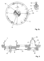
- FIG. 1a shows a section of a cryostat arrangement with a cold head 3 of a cryocooler arranged in a shark tube 1 of a cryocontainer 2 .
- a metallic valve housing 4 is fixedly mounted, which has openings 5, for example in the form of holes or slots, as shown in Fig. 1b .
- a movable metallic valve plate 6 which has approximately congruent openings 7 as the valve housing 4 .
- the valve plate 6 is, as shown in Fig. 1a, pressed with a spring 8 on the valve housing 4, with no further sealing material between the valve plate 6 and the valve housing 4 is located.
- valve plate 6 By turning the valve plate 6, it is possible to bring the openings 7 of the valve plate 6 with the openings 5 of the valve housing 4 in coincidence, so that between neck tube 1 and cryocontainer 2 unhindered gas exchange can take place. Conversely, the openings 5, 7 can be closed by turning the valve plate 6. In this case, gas exchange between cryocontainer 2 and neck tube 1 is no longer possible, apart from the minimal leakage through the narrow gap between valve plate 6 and valve housing 4.
- the valve housing 4 can be fastened with special locking elements 34 to the neck tube opening in the cryocontainer 2 and is thus releasably connected to it and not firmly connected (welded or soldered). Thus, the entire closure can be easily removed and installed and possibly existing Kryostatan angelen can still be retrofitted.
- the cold head 3 of the cryocooler which is located in the neck tube 1, can - after release of a lock - be rotated freely in the neck tube 1, wherein it is still guided vertically.
- an actuating element 9 is mounted, which engages in a driver element 10 on the valve plate 6, so the position of the valve plate 6 can be changed via a rotation of the cold head 3.
- Fig. 2a-c show the driver elements 10 and the actuator 9 in different positions.
- the shutter is fully opened when the cold head 3 is rotated to a first stop 11 (Fig. 2a). Subsequently, the cold head 3 still has to be turned back a small predetermined angle, so that actuator 9 and driver elements 10 no longer touch.
- the locking or unlocking of the cold head 3 can be realized, for example, by one or more attached to the upper mounting flange of the cold head 3, extending in the circumferential direction guide gaps 13 , in which a tapered in the rail rail stop element 14 is guided, wherein the guide gaps at the point at the stop element is in the expansion position of the cold head 3, having an opening 15 through which the stop member 14 can be guided to remove the cold head 3.
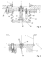
- valve plate 6 can be actuated via a mechanism in the suspension tube 16 of the cryocontainer 2 (FIG. 3).
- a disc-shaped rotary member 18 is mounted below a suspension tube 16 in extension of the axis 17 of the suspension tube 16.
- This can be actuated via a special operating rod 19 , which is inserted into the suspension tube 16 and engages mounted on the rotary member 18 pins 20 .
- the actuating rod 19 can be removed again from the suspension tube 16.
- the rotary member 18 is connected either via a cable 21 or a chain or two rods (a pull and a push rod) or only a rod (which is once on train and at another time to pressure) with the valve plate 6, which is below the neck tube 1 is arranged.
- the fixation of the cable 21 on the rotary member 18 and the valve plate 6 can be done for example via a clamping connection, so that the rotational movement of the actuating rod 19 is transmitted from the rotary member 18 to the valve plate 6.
- the rotary member 18 or the valve plate may be equipped with corresponding stops. This method for actuating the valve plate 6 is recommended especially when the cold head 3 of the cryocooler is rather unsuitable as an actuator, since it should not be claimed for torsion or can not be rotated in tight spaces of the cold head.
- a further embodiment of the cryostat arrangement according to the invention provides for a closure which closes by itself during a quench (FIG. 4).
- a valve plate 22 with valve seat 23 and opening 26 is connected via a bellows 24 with a counter-plate 25 which is mounted at the lower end of the neck tube 1 and has an opening 35.
- the valve plate 22 is vertically movable, while it can only move minimally in the horizontal direction.
- the opening 26 in the valve plate 22 acts as a throttle, so that in the case of a quench a pressure difference across the valve plate 22 is formed.
- the valve plate 22 moves thereby in the direction of a valve plug 27, which is located on the counter-plate 25 and not fixed in the vertical direction, but biased by a spring 28 .
- valve plate 22 and valve plug 27 meet, the gas volume of the neck tube 1 is separated from that of the cryocontainer 2. Since the poppet 27, as mentioned, is not fixed, the valve plate 22 moves depending on the quench pressure under certain circumstances even further up until it rests on three Anschiageiementen 29 . These protect the Weilbaig 24 against inadmissible compression. Further, the spring 28 causes the contact pressure between the valve seat 23 and valve plug 27 is defined.
- an embodiment fulfills the required purpose, in which no actual locking mechanism is present (Fig. 5). Instead, an opening 30 in a plate 31 separating the cryocontainer 2 from the neck tube 1 is so small that in the event of a quench only a small part of the quench gas flows through the neck tube 1 and the largest part is removed via suspension tubes of the cryocontainer 2.
- the opening 30 need only be so large that in normal operation, the steam of the cryogen from the cryocontainer 2 enter the neck tube 1 and can be liquefied at the cold head 3 of the cryocooler. The liquefied cryogen then flows back in countercurrent to the steam from the neck tube 1 in the cryocontainer 2.
- a flow baffle By means of a flow baffle can also be avoided that the exiting in quench steam flows away through the neck tube 1 vertically upwards. Rather, it is guided in the direction of the neck tube wall, causing it to swirl and now leaves the neck tube 1 over the entire cross section.
- Fig. 6 shows an embodiment of the invention in which a manually and automatically activatable shutter are combined.
- the automatic closure is in this case arranged below the manually activatable closure, so that an actuation of the manual closure is realized by the neck tube can.
- other arrangements or combinations of the embodiments described above are possible. By such a configuration, the security of the system can be additionally increased
- All embodiments of the present invention allow a safe installation or removal of a cold head in a neck tube of a cryocontainer.
Landscapes
- Engineering & Computer Science (AREA)
- Physics & Mathematics (AREA)
- Mechanical Engineering (AREA)
- Chemical & Material Sciences (AREA)
- General Physics & Mathematics (AREA)
- Combustion & Propulsion (AREA)
- Condensed Matter Physics & Semiconductors (AREA)
- Thermal Sciences (AREA)
- General Engineering & Computer Science (AREA)
- Power Engineering (AREA)
- Containers, Films, And Cooling For Superconductive Devices (AREA)
- Filling Or Discharging Of Gas Storage Vessels (AREA)
- Magnetic Resonance Imaging Apparatus (AREA)
Applications Claiming Priority (1)
| Application Number | Priority Date | Filing Date | Title |
|---|---|---|---|
| DE102005002011A DE102005002011B3 (de) | 2005-01-15 | 2005-01-15 | Quenchverschluß |
Publications (3)
| Publication Number | Publication Date |
|---|---|
| EP1681576A2 true EP1681576A2 (fr) | 2006-07-19 |
| EP1681576A3 EP1681576A3 (fr) | 2013-01-09 |
| EP1681576B1 EP1681576B1 (fr) | 2017-03-08 |
Family
ID=36120853
Family Applications (1)
| Application Number | Title | Priority Date | Filing Date |
|---|---|---|---|
| EP06000272.2A Ceased EP1681576B1 (fr) | 2005-01-15 | 2006-01-07 | Configuration de cryostat |
Country Status (4)
| Country | Link |
|---|---|
| US (1) | US7503181B2 (fr) |
| EP (1) | EP1681576B1 (fr) |
| JP (1) | JP4790421B2 (fr) |
| DE (1) | DE102005002011B3 (fr) |
Families Citing this family (6)
| Publication number | Priority date | Publication date | Assignee | Title |
|---|---|---|---|---|
| DE102005035894B3 (de) * | 2005-07-30 | 2007-04-05 | Bruker Biospin Gmbh | Supraleitendes Magnetsystem mit Strahlungsschild zwischen Kryofluidtank und Refrigerator |
| US8069675B2 (en) * | 2006-10-10 | 2011-12-06 | Massachusetts Institute Of Technology | Cryogenic vacuum break thermal coupler |
| US8570043B2 (en) * | 2010-10-05 | 2013-10-29 | General Electric Company | System and method for self-sealing a coldhead sleeve of a magnetic resonance imaging system |
| GB2513151B (en) * | 2013-04-17 | 2015-05-20 | Siemens Plc | Improved thermal contact between cryogenic refrigerators and cooled components |
| DE102016224713B3 (de) | 2016-12-12 | 2018-04-05 | Festo Ag & Co. Kg | Stützeinrichtung |
| CN118043694A (zh) * | 2021-12-10 | 2024-05-14 | 上海联影医疗科技股份有限公司 | 成像和治疗的系统和方法 |
Citations (11)
| Publication number | Priority date | Publication date | Assignee | Title |
|---|---|---|---|---|
| DE2906060A1 (de) | 1978-02-21 | 1979-08-30 | Varian Associates | Kryostat |
| US5563566A (en) | 1995-11-13 | 1996-10-08 | General Electric Company | Cryogen-cooled open MRI superconductive magnet |
| US5613367A (en) | 1995-12-28 | 1997-03-25 | General Electric Company | Cryogen recondensing superconducting magnet |
| US5782095A (en) | 1997-09-18 | 1998-07-21 | General Electric Company | Cryogen recondensing superconducting magnet |
| EP0905524A1 (fr) | 1997-09-30 | 1999-03-31 | Oxford Magnet Technology Limited | Agencement d'aimants pour la RMN avec un col logeant un cryogénérateurr du type à tube pulsé |
| EP0905436A2 (fr) | 1997-09-30 | 1999-03-31 | Oxford Magnet Technology Limited | Moyens portants pour RMN systèmes de cryostats |
| US5966944A (en) | 1997-04-09 | 1999-10-19 | Aisin Seiki Kabushiki Kaisha | Superconducting magnet system outfitted with cooling apparatus |
| US20020002830A1 (en) | 2000-07-08 | 2002-01-10 | Bruker Analytik Gmbh | Circulating cryostat |
| WO2003036207A2 (fr) | 2001-10-19 | 2003-05-01 | Oxford Magnet Technology Ltd. | Gaine pour refrigerateur a tube pulse |
| WO2003036190A1 (fr) | 2001-10-19 | 2003-05-01 | Oxford Magnet Technology Ltd. | Refrigerateur a tube pulse comportant une gaine d'isolation |
| US20030230089A1 (en) | 2002-06-14 | 2003-12-18 | Bruker Biospin Gmbh | Cryostat configuration with improved properties |
Family Cites Families (13)
| Publication number | Priority date | Publication date | Assignee | Title |
|---|---|---|---|---|
| US4279127A (en) * | 1979-03-02 | 1981-07-21 | Air Products And Chemicals, Inc. | Removable refrigerator for maintaining liquefied gas inventory |
| US4633682A (en) * | 1986-02-04 | 1987-01-06 | General Electric Company | Horizontal cryostat insert with a vertical service stack |
| DE3915788C2 (de) * | 1989-05-13 | 1994-09-15 | Spectrospin Ag | Kryostat mit einem Überdruckdeckel |
| US5111665A (en) * | 1991-02-19 | 1992-05-12 | General Electric Company | Redundant cryorefrigerator system for a refrigerated superconductive magnet |
| GB2264159B (en) * | 1992-02-05 | 1995-06-28 | Oxford Magnet Tech | Improvements in or relating to liquid helium topping-up apparatus |
| US5249425A (en) * | 1992-07-01 | 1993-10-05 | Apd Cryogenics Inc. | Venting control system for cryostats |
| US5385010A (en) * | 1993-12-14 | 1995-01-31 | The United States Of America As Represented By The Secretary Of The Army | Cryogenic cooler system |
| US5430423A (en) * | 1994-02-25 | 1995-07-04 | General Electric Company | Superconducting magnet having a retractable cryocooler sleeve assembly |
| GB2307045B (en) * | 1995-11-08 | 2000-06-14 | Oxford Magnet Tech | Improvements in or relating to super-conducting nagnets |
| US5682751A (en) * | 1996-06-21 | 1997-11-04 | General Atomics | Demountable thermal coupling and method for cooling a superconductor device |
| US5936499A (en) * | 1998-02-18 | 1999-08-10 | General Electric Company | Pressure control system for zero boiloff superconducting magnet |
| US6109042A (en) * | 1998-12-12 | 2000-08-29 | General Electric Company | Superconducting magnet burst disk venting mechanism |
| US6591854B1 (en) * | 2000-12-14 | 2003-07-15 | Ge Medical Systems Global Technology Company, Llc | Superconductive magnet burst disk assembly |
-
2005
- 2005-01-15 DE DE102005002011A patent/DE102005002011B3/de not_active Expired - Fee Related
- 2005-12-02 US US11/291,990 patent/US7503181B2/en not_active Expired - Fee Related
-
2006
- 2006-01-07 EP EP06000272.2A patent/EP1681576B1/fr not_active Ceased
- 2006-01-13 JP JP2006006352A patent/JP4790421B2/ja not_active Expired - Fee Related
Patent Citations (11)
| Publication number | Priority date | Publication date | Assignee | Title |
|---|---|---|---|---|
| DE2906060A1 (de) | 1978-02-21 | 1979-08-30 | Varian Associates | Kryostat |
| US5563566A (en) | 1995-11-13 | 1996-10-08 | General Electric Company | Cryogen-cooled open MRI superconductive magnet |
| US5613367A (en) | 1995-12-28 | 1997-03-25 | General Electric Company | Cryogen recondensing superconducting magnet |
| US5966944A (en) | 1997-04-09 | 1999-10-19 | Aisin Seiki Kabushiki Kaisha | Superconducting magnet system outfitted with cooling apparatus |
| US5782095A (en) | 1997-09-18 | 1998-07-21 | General Electric Company | Cryogen recondensing superconducting magnet |
| EP0905524A1 (fr) | 1997-09-30 | 1999-03-31 | Oxford Magnet Technology Limited | Agencement d'aimants pour la RMN avec un col logeant un cryogénérateurr du type à tube pulsé |
| EP0905436A2 (fr) | 1997-09-30 | 1999-03-31 | Oxford Magnet Technology Limited | Moyens portants pour RMN systèmes de cryostats |
| US20020002830A1 (en) | 2000-07-08 | 2002-01-10 | Bruker Analytik Gmbh | Circulating cryostat |
| WO2003036207A2 (fr) | 2001-10-19 | 2003-05-01 | Oxford Magnet Technology Ltd. | Gaine pour refrigerateur a tube pulse |
| WO2003036190A1 (fr) | 2001-10-19 | 2003-05-01 | Oxford Magnet Technology Ltd. | Refrigerateur a tube pulse comportant une gaine d'isolation |
| US20030230089A1 (en) | 2002-06-14 | 2003-12-18 | Bruker Biospin Gmbh | Cryostat configuration with improved properties |
Non-Patent Citations (1)
| Title |
|---|
| MAGNETIC RESONANCE, vol. 6, 1993, pages 255 - 273 |
Also Published As
| Publication number | Publication date |
|---|---|
| JP4790421B2 (ja) | 2011-10-12 |
| JP2006253655A (ja) | 2006-09-21 |
| EP1681576B1 (fr) | 2017-03-08 |
| EP1681576A3 (fr) | 2013-01-09 |
| DE102005002011B3 (de) | 2006-04-20 |
| US7503181B2 (en) | 2009-03-17 |
| US20080092557A1 (en) | 2008-04-24 |
Similar Documents
| Publication | Publication Date | Title |
|---|---|---|
| EP1736723B1 (fr) | Dispositif de cryostat avec cryorefroidisseur | |
| EP1628109B1 (fr) | Dispositif de cryostat | |
| EP3296669B1 (fr) | Ensemble cryostat doté d'un réservoir à vide et d'un objet à refroidir et doté d'un espace creux pouvant être vidé | |
| EP3285032B1 (fr) | Agencement de cryostat et son procédé de fonctionnement | |
| DE4017213C1 (fr) | ||
| DE19726943C2 (de) | Kältemittelkompressor | |
| DE69828128T2 (de) | Magnetanordnung für die Kernspinresonanz mit einem Halsrohr, in dem ein Pulsrohrkühler untergebracht ist | |
| DE102004037173B3 (de) | Vorrichtung zur kryogenverlustfreien Kühlung einer Kryostatanordnung | |
| EP3382411B1 (fr) | Dispositif formant cryostat pourvu de col tubulaire à une structure porteuse et un col tubulaire entourant la structure porteuse destiné à réduire la consommation de cryogène | |
| EP3282270B1 (fr) | Appareil rmn pourvu d'un système d'aimants supraconducteurs et composants formant sondes refroidis | |
| EP0398156B1 (fr) | Procédé et dispositif pour préréfrigérer le réservoir d'hélium d'un cryostat | |
| EP1681576B1 (fr) | Configuration de cryostat | |
| DE102008033467B4 (de) | Kryostat für supraleitende MR-Magnete | |
| DE4039365A1 (de) | Nmr-magnetsystem mit supraleitender spule in einem low-loss-kryostaten | |
| DE2942305A1 (de) | Kryopumpe und kryosammler zum aufsammeln von luftproben sowie angepasste schleusenvorrichtung | |
| EP4109121B1 (fr) | Refroidissement autonome d'un système supraconducteur de bobine magnétique rm à refroidissement à sec | |
| EP3953724B1 (fr) | Ensemble de mesure à résonance magnétique nucléaire (rmn) à trou froid du cryostat | |
| EP4006567B1 (fr) | Système magnétique destiné à la mise en oeuvre des expériences rmn à 2 champs et procédé de mise à niveau associé | |
| EP1742234B1 (fr) | Ensemble de cryostat horizontal en surfusion | |
| DE102012212063A1 (de) | Magnetfelderzeugungsvorrichtung mit alternativer Quenchvorrichtung | |
| EP3486671B1 (fr) | Dispositif de tête d'échantillon rmn pour mas à stator interchangeable | |
| DE4112661A1 (de) | Vorrichtung zur anbringung eines messgebers an einer wand, insbesondere eines behaelters | |
| DE202005010892U1 (de) | Unterkühlte Horizontalkryostatanordnung | |
| DE102006047589B4 (de) | Anlage zur Untersuchung von Objekten mittels magnetischer Resonanz | |
| DE4039332A1 (de) | Nmr-magnetsystem mit supraleitender spule in einem unterkuehlten heliumbad auf atmosphaerendruck |
Legal Events
| Date | Code | Title | Description |
|---|---|---|---|
| PUAI | Public reference made under article 153(3) epc to a published international application that has entered the european phase |
Free format text: ORIGINAL CODE: 0009012 |
|
| AK | Designated contracting states |
Kind code of ref document: A2 Designated state(s): AT BE BG CH CY CZ DE DK EE ES FI FR GB GR HU IE IS IT LI LT LU LV MC NL PL PT RO SE SI SK TR |
|
| AX | Request for extension of the european patent |
Extension state: AL BA HR MK YU |
|
| PUAL | Search report despatched |
Free format text: ORIGINAL CODE: 0009013 |
|
| AK | Designated contracting states |
Kind code of ref document: A3 Designated state(s): AT BE BG CH CY CZ DE DK EE ES FI FR GB GR HU IE IS IT LI LT LU LV MC NL PL PT RO SE SI SK TR |
|
| AX | Request for extension of the european patent |
Extension state: AL BA HR MK YU |
|
| RIC1 | Information provided on ipc code assigned before grant |
Ipc: F25D 19/00 20060101ALI20121205BHEP Ipc: G01R 33/38 20060101AFI20121205BHEP |
|
| 17P | Request for examination filed |
Effective date: 20130122 |
|
| AKX | Designation fees paid |
Designated state(s): CH DE FR GB LI |
|
| 17Q | First examination report despatched |
Effective date: 20140508 |
|
| GRAP | Despatch of communication of intention to grant a patent |
Free format text: ORIGINAL CODE: EPIDOSNIGR1 |
|
| INTG | Intention to grant announced |
Effective date: 20160202 |
|
| GRAP | Despatch of communication of intention to grant a patent |
Free format text: ORIGINAL CODE: EPIDOSNIGR1 |
|
| INTG | Intention to grant announced |
Effective date: 20160531 |
|
| GRAS | Grant fee paid |
Free format text: ORIGINAL CODE: EPIDOSNIGR3 |
|
| GRAA | (expected) grant |
Free format text: ORIGINAL CODE: 0009210 |
|
| AK | Designated contracting states |
Kind code of ref document: B1 Designated state(s): CH DE FR GB LI |
|
| REG | Reference to a national code |
Ref country code: GB Ref legal event code: FG4D Free format text: NOT ENGLISH |
|
| REG | Reference to a national code |
Ref country code: DE Ref legal event code: R081 Ref document number: 502006015395 Country of ref document: DE Owner name: BRUKER SWITZERLAND AG, CH Free format text: FORMER OWNER: BRUKER BIOSPIN AG, FAELLANDEN, CH |
|
| REG | Reference to a national code |
Ref country code: CH Ref legal event code: EP |
|
| REG | Reference to a national code |
Ref country code: DE Ref legal event code: R096 Ref document number: 502006015395 Country of ref document: DE |
|
| REG | Reference to a national code |
Ref country code: DE Ref legal event code: R097 Ref document number: 502006015395 Country of ref document: DE |
|
| PLBE | No opposition filed within time limit |
Free format text: ORIGINAL CODE: 0009261 |
|
| STAA | Information on the status of an ep patent application or granted ep patent |
Free format text: STATUS: NO OPPOSITION FILED WITHIN TIME LIMIT |
|
| REG | Reference to a national code |
Ref country code: FR Ref legal event code: PLFP Year of fee payment: 13 |
|
| 26N | No opposition filed |
Effective date: 20171211 |
|
| REG | Reference to a national code |
Ref country code: DE Ref legal event code: R082 Ref document number: 502006015395 Country of ref document: DE Representative=s name: KOHLER SCHMID MOEBUS PATENTANWAELTE PARTNERSCH, DE Ref country code: DE Ref legal event code: R081 Ref document number: 502006015395 Country of ref document: DE Owner name: BRUKER SWITZERLAND AG, CH Free format text: FORMER OWNER: BRUKER BIOSPIN AG, FAELLANDEN, CH |
|
| REG | Reference to a national code |
Ref country code: CH Ref legal event code: PFA Owner name: BRUKER SWITZERLAND AG, CH Free format text: FORMER OWNER: BRUKER BIOSPIN AG, CH |
|
| PGFP | Annual fee paid to national office [announced via postgrant information from national office to epo] |
Ref country code: GB Payment date: 20200127 Year of fee payment: 15 Ref country code: DE Payment date: 20200123 Year of fee payment: 15 |
|
| PGFP | Annual fee paid to national office [announced via postgrant information from national office to epo] |
Ref country code: CH Payment date: 20200127 Year of fee payment: 15 |
|
| PGFP | Annual fee paid to national office [announced via postgrant information from national office to epo] |
Ref country code: FR Payment date: 20200123 Year of fee payment: 15 |
|
| REG | Reference to a national code |
Ref country code: DE Ref legal event code: R119 Ref document number: 502006015395 Country of ref document: DE |
|
| REG | Reference to a national code |
Ref country code: CH Ref legal event code: PL |
|
| GBPC | Gb: european patent ceased through non-payment of renewal fee |
Effective date: 20210107 |
|
| PG25 | Lapsed in a contracting state [announced via postgrant information from national office to epo] |
Ref country code: FR Free format text: LAPSE BECAUSE OF NON-PAYMENT OF DUE FEES Effective date: 20210131 |
|
| PG25 | Lapsed in a contracting state [announced via postgrant information from national office to epo] |
Ref country code: LI Free format text: LAPSE BECAUSE OF NON-PAYMENT OF DUE FEES Effective date: 20210131 Ref country code: GB Free format text: LAPSE BECAUSE OF NON-PAYMENT OF DUE FEES Effective date: 20210107 Ref country code: DE Free format text: LAPSE BECAUSE OF NON-PAYMENT OF DUE FEES Effective date: 20210803 Ref country code: CH Free format text: LAPSE BECAUSE OF NON-PAYMENT OF DUE FEES Effective date: 20210131 |