EP1681845A2 - Impression et balayage d'information - Google Patents
Impression et balayage d'information Download PDFInfo
- Publication number
- EP1681845A2 EP1681845A2 EP05111484A EP05111484A EP1681845A2 EP 1681845 A2 EP1681845 A2 EP 1681845A2 EP 05111484 A EP05111484 A EP 05111484A EP 05111484 A EP05111484 A EP 05111484A EP 1681845 A2 EP1681845 A2 EP 1681845A2
- Authority
- EP
- European Patent Office
- Prior art keywords
- paper
- sheet
- image input
- image
- printing
- Prior art date
- Legal status (The legal status is an assumption and is not a legal conclusion. Google has not performed a legal analysis and makes no representation as to the accuracy of the status listed.)
- Withdrawn
Links
Images




Classifications
-
- H—ELECTRICITY
- H04—ELECTRIC COMMUNICATION TECHNIQUE
- H04N—PICTORIAL COMMUNICATION, e.g. TELEVISION
- H04N1/00—Scanning, transmission or reproduction of documents or the like, e.g. facsimile transmission; Details thereof
- H04N1/04—Scanning arrangements, i.e. arrangements for the displacement of active reading or reproducing elements relative to the original or reproducing medium, or vice versa
- H04N1/207—Simultaneous scanning of the original picture and the reproduced picture with a common scanning device
-
- H—ELECTRICITY
- H04—ELECTRIC COMMUNICATION TECHNIQUE
- H04N—PICTORIAL COMMUNICATION, e.g. TELEVISION
- H04N1/00—Scanning, transmission or reproduction of documents or the like, e.g. facsimile transmission; Details thereof
- H04N1/04—Scanning arrangements, i.e. arrangements for the displacement of active reading or reproducing elements relative to the original or reproducing medium, or vice versa
- H04N1/10—Scanning arrangements, i.e. arrangements for the displacement of active reading or reproducing elements relative to the original or reproducing medium, or vice versa using flat picture-bearing surfaces
- H04N1/1013—Scanning arrangements, i.e. arrangements for the displacement of active reading or reproducing elements relative to the original or reproducing medium, or vice versa using flat picture-bearing surfaces with sub-scanning by translatory movement of at least a part of the main-scanning components
- H04N1/1017—Scanning arrangements, i.e. arrangements for the displacement of active reading or reproducing elements relative to the original or reproducing medium, or vice versa using flat picture-bearing surfaces with sub-scanning by translatory movement of at least a part of the main-scanning components the main-scanning components remaining positionally invariant with respect to one another in the sub-scanning direction
-
- H—ELECTRICITY
- H04—ELECTRIC COMMUNICATION TECHNIQUE
- H04N—PICTORIAL COMMUNICATION, e.g. TELEVISION
- H04N1/00—Scanning, transmission or reproduction of documents or the like, e.g. facsimile transmission; Details thereof
- H04N1/04—Scanning arrangements, i.e. arrangements for the displacement of active reading or reproducing elements relative to the original or reproducing medium, or vice versa
- H04N1/19—Scanning arrangements, i.e. arrangements for the displacement of active reading or reproducing elements relative to the original or reproducing medium, or vice versa using multi-element arrays
- H04N1/191—Scanning arrangements, i.e. arrangements for the displacement of active reading or reproducing elements relative to the original or reproducing medium, or vice versa using multi-element arrays the array comprising a one-dimensional [1D] array
- H04N1/1911—Simultaneously or substantially simultaneously scanning picture elements on more than one main scanning line, e.g. scanning in swaths
- H04N1/1916—Simultaneously or substantially simultaneously scanning picture elements on more than one main scanning line, e.g. scanning in swaths using an array of elements displaced from one another in the main scan direction, e.g. a diagonally arranged array
- H04N1/1917—Staggered element array, e.g. arrays with elements arranged in a zigzag
-
- H—ELECTRICITY
- H04—ELECTRIC COMMUNICATION TECHNIQUE
- H04N—PICTORIAL COMMUNICATION, e.g. TELEVISION
- H04N1/00—Scanning, transmission or reproduction of documents or the like, e.g. facsimile transmission; Details thereof
- H04N1/04—Scanning arrangements, i.e. arrangements for the displacement of active reading or reproducing elements relative to the original or reproducing medium, or vice versa
- H04N1/19—Scanning arrangements, i.e. arrangements for the displacement of active reading or reproducing elements relative to the original or reproducing medium, or vice versa using multi-element arrays
- H04N1/191—Scanning arrangements, i.e. arrangements for the displacement of active reading or reproducing elements relative to the original or reproducing medium, or vice versa using multi-element arrays the array comprising a one-dimensional [1D] array
- H04N1/1911—Simultaneously or substantially simultaneously scanning picture elements on more than one main scanning line, e.g. scanning in swaths
- H04N1/1912—Scanning main scanning lines which are spaced apart from one another in the sub-scanning direction
-
- H—ELECTRICITY
- H04—ELECTRIC COMMUNICATION TECHNIQUE
- H04N—PICTORIAL COMMUNICATION, e.g. TELEVISION
- H04N1/00—Scanning, transmission or reproduction of documents or the like, e.g. facsimile transmission; Details thereof
- H04N1/04—Scanning arrangements, i.e. arrangements for the displacement of active reading or reproducing elements relative to the original or reproducing medium, or vice versa
- H04N1/19—Scanning arrangements, i.e. arrangements for the displacement of active reading or reproducing elements relative to the original or reproducing medium, or vice versa using multi-element arrays
- H04N1/191—Scanning arrangements, i.e. arrangements for the displacement of active reading or reproducing elements relative to the original or reproducing medium, or vice versa using multi-element arrays the array comprising a one-dimensional [1D] array
- H04N1/192—Simultaneously or substantially simultaneously scanning picture elements on one main scanning line
- H04N1/193—Simultaneously or substantially simultaneously scanning picture elements on one main scanning line using electrically scanned linear arrays, e.g. linear CCD arrays
-
- H—ELECTRICITY
- H04—ELECTRIC COMMUNICATION TECHNIQUE
- H04N—PICTORIAL COMMUNICATION, e.g. TELEVISION
- H04N2201/00—Indexing scheme relating to scanning, transmission or reproduction of documents or the like, and to details thereof
- H04N2201/0077—Types of the still picture apparatus
- H04N2201/0081—Image reader
-
- H—ELECTRICITY
- H04—ELECTRIC COMMUNICATION TECHNIQUE
- H04N—PICTORIAL COMMUNICATION, e.g. TELEVISION
- H04N2201/00—Indexing scheme relating to scanning, transmission or reproduction of documents or the like, and to details thereof
- H04N2201/0077—Types of the still picture apparatus
- H04N2201/0082—Image hardcopy reproducer
Definitions
- the present invention relates to the printing and scanning of information.
- FIG. 1 is a schematic perspective view of a conventional image input/output apparatus.
- a shuttle-type inkjet head 2 and a scan unit 3 are mounted on a carriage 1 that moves backwards and forwards in a main scanning direction M.
- a sheet of paper P and a document D are fed along a common feed path by a common feed unit 4.
- the feed unit 4 feeds the document D in a sub-scanning direction S.
- the scan unit 3 reads the image from the document D.
- the feed unit 4 feeds the sheet of paper P in the sub-scanning direction S.
- the inkjet head 2 ejects ink to the sheet of paper P to print the image.
- the image input/output apparatus is structured in a simple manner, such that the sheet of paper P and the document D are fed along the common feed path by the common feed unit 4.
- the conventional image input/output apparatus has the following drawbacks.
- the feed unit 4 is generally designed to feed the sheet of paper P, the sheet of paper P and the document D must be limited to an allowable thickness to ensure that it is properly fed.
- documents D have various thicknesses. If a document D has a thickness that is greater than the allowable thickness or a defective document D is fed into the apparatus, feeding precision deteriorates.
- the present invention aims to address the above problems.
- apparatus comprising page scanning means and printing means which are configured to face in substantially different directions to one another, such that printing and scanning can be performed substantially simultaneously.
- a combined printer and scanner apparatus comprising an apparatus according to the first aspect, a page support for supporting a page to be scanned by the page scanning means and a platen to support a page to be printed by the printing means, wherein the combined printer/scanner module is located between the page support and the platen and the page scanning means faces the page support and the printing means faces the platen.
- the combined printer and scanner apparatus may be configured such that when operating in a copying mode, the page scanning means is operable to scan a first line on the page and after the first line has been scanned, the printing means is operable to print a copy of the first line before a second line is scanned.
- the printing means may be an inkjet array head having a nozzle unit substantially extending across the width of the page to be printed and the printing means and document scanning means are configured to be moved in the same direction.
- an image input/output apparatus comprising a document support on which a document can be loaded, a platen disposed in parallel to the document support for allowing a sheet of paper to be loaded thereon, and an image input/output module disposed between the document support and the platen and configured to be moved in a sub-scanning direction, wherein the image input/output module comprises an array inkjet head including a nozzle unit with a length corresponding to a width of the sheet of paper for printing an image on the sheet of paper and a scan unit for reading image information from the document.
- the image input/output apparatus may further comprise a feed unit for drawing up and loading the sheet of paper on the platen, and a discharge unit for discharging the sheet of paper on which printing is completed.
- the sheet of paper While printing is performed by the array inkjet head, the sheet of paper may be in a position selected from the group consisting of a position wherein a front end of the sheet of paper is inserted into the discharge unit, a position wherein a rear end of the sheet of paper is inserted into the feed unit, and a position wherein the front end and the rear end of the sheet of paper are inserted into the discharge unit and the feed unit, respectively.
- the platen may be comprised of a belt that is circulated in the sub-scanning direction.
- the image input/output apparatus may further comprise a negative pressure providing unit disposed under the platen for providing a negative pressure to prevent the sheet of paper from coming off the platen.
- the image input/output apparatus may further comprise guide members installed in the sub-scanning direction for guiding the image input/output module in the sub-scanning direction, and a motor for moving the image input/output module in the sub-scanning direction.
- the image input/output apparatus may further comprise a paper supply cassette on which the sheet of paper is loaded, wherein the paper supply cassette is disposed under the platen and forms a C-shaped paper feed path.
- the image input/output apparatus may further comprise a paper supply cassette on which the sheet of paper is loaded, wherein the paper supply cassette is installed in the form of a bin and forms an L-shaped paper feed path.
- an image input/output module comprising an array inkjet head including a nozzle unit with a length corresponding to a width of a sheet of paper for printing an image on the sheet of paper, and a scan unit directed in a direction opposite to that of the inkjet head for reading image information from a document.
- a method is provided of inputting and outputting an image using an image input/output apparatus that includes a document support, a platen, and an image input/output module having an array inkjet head and a scan unit disposed between the document support and the platen, the method comprising the steps of reading image information on at least one line from the document loaded on the document support using the scan unit while moving the image input/output module in a sub-scanning direction, converting the read image information into print information, and printing an image on a sheet of paper loaded on a platen according to the print information using the inkjet head.
- a method is provided of inputting and outputting an image using an image input/output apparatus that includes a document support, a platen, and an image input/output module having an array inkjet head and a scan unit disposed between the document support and the platen, the method comprising the steps of reading image information corresponding to one page from the document loaded on the document support using the scan unit while moving the image input/output module in a sub-scanning direction, converting the read image information into print information, and printing an image on a sheet of paper loaded on the platen according to the print information using the image input/output module.
- the printing of the image on the sheet of paper may comprise the step of printing an image on a sheet of paper while moving the image input/output module in a direction opposite to the direction during the scanning.
- the printing of the image on the sheet of paper may further comprise the step of returning the image input/output module to its original position and printing an image on a sheet of paper while moving the same in the sub-scanning direction again.
- the printing of the image on the sheet of paper may still further comprise the step of placing the image input/output module at a predetermined position and printing an image on a sheet of paper while moving the sheet of paper in the sub-scanning direction.
- the method may further comprise the step of supplying the sheet of paper into position on the platen before the reading of the image information from the document.
- the sheet of paper may be placed in a position selected from the group consisting of a position wherein a front end of the sheet of paper is inserted into a discharge unit, a position wherein a rear end of the sheet of paper is inserted into a feed unit, and a position wherein the front end and the rear end of the sheet of paper are respectively inserted into the discharge unit and the feed unit.
- the image input/output apparatus comprises a transparent document support 10 on which a document D is loaded, a platen 20 on which a sheet of paper P is loaded, and an image input/output module 50.
- the document support 10 and the platen 20 are disposed in parallel to each other, and the image input/output module 50 is disposed between the document support 10 and the platen 20.
- the image input/output module 50 comprises an inkjet head 30 which ejects ink onto the sheet of paper P to print an image, and a scan unit 40 which reads image information from the document D.
- the scan unit 40 and the inkjet head 30 are directed to face in opposite directions.
- the inkjet head 30 of the exemplary embodiment includes a nozzle unit 31 having a length extending in the main scanning direction M that corresponds to the width of the sheet of paper P.
- An example of the nozzle unit 31 is illustrated in Figure 5.
- the inkjet head 30 further includes an ink cartridge in which ink is stored, a chamber with an ejecting unit (such as a piezo element or a heater) connected with the respective nozzles 32 and providing a pressure to eject ink, a fluid path through which ink is supplied from the ink cartridge to the chamber, and so on.
- an ejecting unit such as a piezo element or a heater
- the nozzle unit 31 depicted in Figure 5 is just one example and the scope of the present invention is not limited to the shape and configuration of the nozzle unit 31 depicted in Figure 5.
- a contact-type image sensor (CIS) or a charge-coupled device (CCD), which can input an image line by line, can be used as the scan unit 40. Since the structure and operating principles of the CIS and the CCD are well known to those skilled in the art, a detailed explanation thereof will not be given.
- the platen 20 supports a rear surface of the sheet of paper P and maintains a distance between a top surface of the sheet of paper P and the nozzle unit 31.
- the distance may range from about 0.5 mm to about 2.5 mm.
- the image input/output apparatus may further comprise a negative pressure providing unit that provides a negative pressure to the rear surface of the sheet of paper P to ensure that the top surface of the paper P lies flat on the platen 20.
- the negative pressure providing unit may comprise air vents 21 formed in the platen 20, and a fan 22 disposed under the platen 20. The fan 22 will then suck air in through the air vents 21 as shown in Figure 2 to prevent the sheet of paper P from coming off the platen 20.
- various apparatuses such as a vacuum sucking device may be used as the negative pressure providing unit in other embodiments of the present invention.
- a feed unit 60 is provided for drawing up and loading the sheet of paper P onto the platen 20 and is installed at an inlet side of the inkjet head 30.
- the feed unit 60 comprises a feed roller 61, and an idle roller 62 which contacts and is driven by the feed roller 61.
- a discharge unit 70 is provided for discharging the printed sheet of paper P from the platen 20.
- the discharge unit 70 is installed at an outlet side of the platen 20.
- the discharge unit 70 comprises a discharge roller 71, and a star wheel 72 which contacts and is rotated by the discharge roller 71. A point-contacting surface on the star wheel 72 contacts the top surface of the sheet of paper P.
- a paper supply cassette 80 into which sheets of paper P are loaded is located under the platen 20 as shown in Figure 2.
- the paper supply cassette 80 is located such that a C-shaped paper feed path is formed. This construction reduces the "foot-print" of the image input/output apparatus ensuring that minimal desk space is taken up by the apparatus.
- a multi-purpose tray 82 may be further provided.
- the paper supply cassette 80 may also be installed at one side of the image input/output apparatus in the form of a bin as shown in Figure 3. This will form an L-shaped paper feed path. As is seen from the embodiment of Figure 3, the construction of the apparatus therein achieves a slim-line image input/output apparatus.
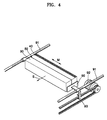
- the image input/output module 50 is moved in a sub-scanning direction S.
- the image input/output module 50 is mounted on a carriage 90.
- the carriage 90 is supported by shafts (or guide members) 91 that are installed in the sub-scanning direction S.
- the carriage 90 is connected to a timing belt (or a wire) 93 that is moved by a motor 92.
- the image input/output module 50 is moved backwards and forwards in the sub-scanning direction S by rotating the motor 92 in forward and reverse directions.
- the scan unit 40 and the inkjet head 30 are also mounted on the carriage 90.
- the inkjet head 30 may be mounted on the carriage 90 and the scan unit 40 may be coupled to the inkjet head 30.
- the inkjet head 30 and the scan unit 40 may be integrally formed with one another. If the inkjet head 30 and the scan unit 40 are integrally formed with one another, they can share common parts, such as a cable (not shown) which is used for providing electrical connections to a control unit (not shown), and a frame (not shown) which defines the outer appearance of the image input/output module 50. Further, in yet another embodiment of the present invention, the scan unit 40 and the inkjet head 30 may be directly supported by the shafts 91 without the carriage 90.
- a pickup roller 81 picks up a sheet of paper P from the paper supply cassette 80, and supplies this to the feed unit 60.
- the feed unit 60 draws up and loads the sheet of paper P onto the platen 20.
- the sheet of paper P is supported by the platen 20 such that a predetermined distance is maintained between the sheet of paper P and the nozzle unit 31. If the motor 92 is rotated normally (rotated in a forward direction), the image input/output module 50 is moved in the sub-scanning direction S.
- the inkjet head 30 ejects ink onto the sheet of paper P to print an image.
- the sheet of paper P is discharged by the discharge unit 70. If the motor 92 is then rotated in the reverse direction, the image input/output module 50 returns to its original position.
- the sheet of paper P can be fed by the feed unit 60 towards the discharge unit 70 while the inkjet head 30 is in its fixed position and ejects ink onto the sheet of paper P to print the image.
- the document D is loaded onto the document support 10 and a document cover 11 is closed. If a user presses an image input button 84 on an operation panel 83, or sends an image input command through the host computer (not shown), the motor 92 is rotated in the forward direction and thus, the image input/output module 50 is moved in the sub-scanning direction S.
- the scan unit 40 emits light onto the document D, detects the reflected light signal, and reads image information printed on the document D.
- the image information is then transferred to a storage device (not shown) of the host computer. After the scanning is completed, if the motor 92 is rotated in the reverse direction, the image input/output module 50 returns to its original position.
- the document D To copy the document D, it is loaded on the document support 10 and the document cover 11 is closed. If the user presses a copy button 85 on the operation panel 83, or sends a copy command through the host computer, the sheet of paper P is picked up by the pickup roller 81 from the paper supply cassette 80 and is drawn up and loaded on the platen 20 by the feed unit 60.
- the printing operation is performed. If the motor 92 is rotated in the forward direction, the image input/output module 50 is moved in the sub-scanning direction S.
- the scan unit 40 emits light onto the document D, detects the reflected light signal, and reads a line of image information or a band of image information containing a plurality of lines recorded on the document D.
- the image information is converted into print information using an image processor (not shown) and is then input to the inkjet head 30.
- the inkjet head 30 ejects ink in accordance with the print information so as to print an image on the sheet of paper P.
- the image processor converts the image information into the print information in almost real time, scanning and printing operations are simultaneously performed with a gap of one line or one band therebetween. Accordingly, almost real time copying is possible.
- the exemplary embodiment of the image input/output apparatus therefore needs only a small buffer memory that is capable of storing image information of at least one line or one band. Accordingly, a more inexpensive image input/output apparatus compared with a conventional image input/output apparatus can be realized, in which the document and the sheet of paper have the same path.
- an image forming apparatus employing the array inkjet head 30 is structured such that the inkjet head 30 is stationary and the sheet of paper P is moved in the sub-scanning direction S.
- the scan unit 40 should preferably be moved in the sub-scanning direction S.
- the motor 92 for moving the scan unit 40 and a motor (not shown) for feeding the sheet of paper P should be simultaneously driven to perform copying, the image forming apparatus should preferably precisely control both motors, which increases the burden on a control unit (not shown). Also, the vibration of the motor generated during the feeding of the sheet of paper P may affect the scanning, thereby deteriorating scanning precision.
- the image input/output apparatus of the exemplary embodiments of the present invention moves the inkjet head 30 and the scan unit 40 alike in the sub-scanning direction S, and does not feed the sheet of paper P during the copying process. Accordingly, only the motor 92 for moving the inkjet head 30 and the scan unit 40 needs to be controlled, thereby reducing the burden on the control unit. Also, vibration is low and thus, precise scanning can be achieved.
- the feeding precision of the sheet of paper P is lower than the feeding precision of the inkjet head 30. Since the sheet of paper P is fed using the frictional force between the feed roller 61, the idle roller 62, and the sheet of paper P, a slip may occur. Since the inkjet head 30 is moved by the very precise timing looped belt (or wire) 93 and guided by the shafts 91, the inkjet head 30 can be moved in a very precise manner.
- the exemplary image input/output apparatus of the present embodiment can ensure higher print quality than the conventional apparatus in which the inkjet head 30 is fixed and the sheet of paper P is fed in the sub-scanning direction S. Also, since the inkjet head 30 is moved together with the scan unit 40, a separate unit for moving the inkjet head 30 in the sub-scanning direction S is not required.
- a scanning process and a printing process may be separated to further improve scan and print quality.
- image information is read from the front end of the document D while the image input/output module 50 is moved in the sub-scanning direction S, and is then stored in the buffer memory.
- the input image information is converted into print information using the image processor.
- the image input/output module 50 then prints the image on the sheet of paper P according to the print information whilst it is being moved in the direction opposite to the direction during the scanning.
- the input image information is converted into print image for printing using the image processor.
- the copying process can be performed by moving the image input/output module 50 only once, thereby preventing a low copy speed.
- the image input/output module 50 may return to its original position after the scanning is completed and then move again in the sub-scanning direction S to print an image on the sheet of paper P. Also, the image input/output module 50 may be placed in a position, such as the position after scanning, its original position, or an arbitrary position between these two positions. After the scanning is completed, the sheet of paper P may be moved in the sub-scanning direction S to print an image thereon.
- a display unit such as a liquid crystal display unit may be further provided on the operation panel 83 to display an operating state of the image input/output apparatus.
- the user can recognise the operating state of the image input/output apparatus, for example, which of the operations (including printing, scanning, and copying) is being performed or whether the operation is completed, from the information displayed on the display unit.
- the platen 20 may be comprised of a belt 25, which is moved in the sub-scanning direction S as shown in Figure 6.
- Figure 6 is a cross-sectional view of an image input/output apparatus according to still another embodiment of the present invention.
- the air vents 21 are formed in the belt 25.
- the fan 22 sucks air in through the air vents 21 to prevent the sheet of paper P from coming off the belt 25.
- a front end and a rear end of the paper P are spaced apart from the discharge unit 70 and the convey unit 60 while printing. In this case, borderless printing of the sheet of paper P can be achieved so that an image can be printed without white borders.
- the image input/output module, image input/output apparatus, and method for inputting and outputting an image according to an embodiment of the present invention has at least the following advantages.
- an image input/output apparatus that is capable of copying information in almost real time can be realized.
- An inexpensive image input/output apparatus can be realised since copying can be performed with a small buffer memory that only needs to be capable of storing one line or one band of image information.
- a slim flatbed image input/output apparatus having a minimum foot-print design can be realised by adjusting the position of the paper supply cassette.
Landscapes
- Engineering & Computer Science (AREA)
- Multimedia (AREA)
- Signal Processing (AREA)
- Ink Jet (AREA)
- Accessory Devices And Overall Control Thereof (AREA)
- Printers Characterized By Their Purpose (AREA)
Applications Claiming Priority (2)
| Application Number | Priority Date | Filing Date | Title |
|---|---|---|---|
| KR20050004440 | 2005-01-18 | ||
| KR1020050025371A KR100788660B1 (ko) | 2005-01-18 | 2005-03-28 | 화상입출력장치 및 방법 |
Publications (2)
| Publication Number | Publication Date |
|---|---|
| EP1681845A2 true EP1681845A2 (fr) | 2006-07-19 |
| EP1681845A3 EP1681845A3 (fr) | 2006-10-18 |
Family
ID=36168563
Family Applications (1)
| Application Number | Title | Priority Date | Filing Date |
|---|---|---|---|
| EP05111484A Withdrawn EP1681845A3 (fr) | 2005-01-18 | 2005-11-30 | Impression et balayage d'information. |
Country Status (2)
| Country | Link |
|---|---|
| US (1) | US20060158468A1 (fr) |
| EP (1) | EP1681845A3 (fr) |
Cited By (1)
| Publication number | Priority date | Publication date | Assignee | Title |
|---|---|---|---|---|
| EP1909478A3 (fr) * | 2006-09-29 | 2008-10-08 | Samsung Electronics Co., Ltd. | Périphérique multifonctionnel |
Families Citing this family (3)
| Publication number | Priority date | Publication date | Assignee | Title |
|---|---|---|---|---|
| KR100948818B1 (ko) * | 2005-05-09 | 2010-03-22 | 아그파 그래픽스 엔브이 | 자동화된 매체 이송을 구비한 디지털 인쇄용 인쇄기 |
| TW201328311A (zh) * | 2011-12-19 | 2013-07-01 | Kinpo Elect Inc | 掃描與列印裝置及掃描與列印方法 |
| JP6672788B2 (ja) * | 2015-12-25 | 2020-03-25 | ブラザー工業株式会社 | インクジェット記録装置 |
Family Cites Families (11)
| Publication number | Priority date | Publication date | Assignee | Title |
|---|---|---|---|---|
| US4117518A (en) * | 1973-12-03 | 1978-09-26 | Skala Stephen F | Ink drop facsimile system |
| US4314282A (en) * | 1980-04-14 | 1982-02-02 | Xerox Corporation | Multifunction graphic engine based on an oscillating scanner |
| US4583126A (en) * | 1982-11-18 | 1986-04-15 | Xerox Corporation | Raster input/output scanner |
| US4839741A (en) * | 1987-12-07 | 1989-06-13 | Xerox Corporation | Image reproducing apparatus with CCD scanner and bubble jet printer simultaneously driven by a common belt in opposite directions and operated asynchronously |
| JPH01175459A (ja) * | 1987-12-29 | 1989-07-11 | Ricoh Co Ltd | 一体走査型スキャナプリンタ |
| US5153738A (en) * | 1991-05-20 | 1992-10-06 | Xerox Corporation | Scanner with single source mechanical power |
| JPH10244711A (ja) * | 1997-03-05 | 1998-09-14 | Tec Corp | スキャナ付プリンタ |
| KR100288694B1 (ko) * | 1997-12-30 | 2001-05-02 | 윤종용 | 소형 복합기 |
| JP2000062259A (ja) * | 1998-08-19 | 2000-02-29 | Ricoh Co Ltd | インクジェット記録装置 |
| JP2003175617A (ja) * | 2001-08-28 | 2003-06-24 | Ricoh Co Ltd | インクジェット記録装置及び複写装置 |
| CN1274131C (zh) * | 2002-09-27 | 2006-09-06 | 三星电子株式会社 | 组合平台扫描仪/打印机的机器 |
-
2005
- 2005-11-30 EP EP05111484A patent/EP1681845A3/fr not_active Withdrawn
-
2006
- 2006-01-17 US US11/332,634 patent/US20060158468A1/en not_active Abandoned
Cited By (1)
| Publication number | Priority date | Publication date | Assignee | Title |
|---|---|---|---|---|
| EP1909478A3 (fr) * | 2006-09-29 | 2008-10-08 | Samsung Electronics Co., Ltd. | Périphérique multifonctionnel |
Also Published As
| Publication number | Publication date |
|---|---|
| US20060158468A1 (en) | 2006-07-20 |
| EP1681845A3 (fr) | 2006-10-18 |
Similar Documents
| Publication | Publication Date | Title |
|---|---|---|
| US6542263B2 (en) | Automatic document feeder with improved sheet handling capabilities and method of feeding and scanning over-sized media sheets | |
| JP4379366B2 (ja) | 媒体端部検出装置及び画像記録装置 | |
| JP2006272772A (ja) | 画像記録装置 | |
| US20190248158A1 (en) | Ink-jet recording apparatus and ink-jet recording method | |
| JP4613778B2 (ja) | シート検出装置及びこれを備えた画像記録装置 | |
| JP2007223735A (ja) | 画像記録装置 | |
| JP4345700B2 (ja) | 画像記録装置 | |
| KR100958586B1 (ko) | 화상입출력장치 및 방법 | |
| JP4674518B2 (ja) | 画像記録装置 | |
| JP6672788B2 (ja) | インクジェット記録装置 | |
| JP4577029B2 (ja) | インクジェット記録装置 | |
| US20060158468A1 (en) | Image input/output module and image input/output apparatus and method | |
| US7695081B2 (en) | Image input/output apparatus and method | |
| JP4466432B2 (ja) | インクジェット記録装置 | |
| JP4779751B2 (ja) | 画像記録装置 | |
| JP6705523B2 (ja) | インクジェット記録装置及びインクジェット記録方法 | |
| JP4701785B2 (ja) | 画像記録装置 | |
| JP2022161608A (ja) | 読取装置 | |
| JP4581707B2 (ja) | 画像記録装置 | |
| JPH08181820A (ja) | 画像読取記録装置 | |
| JP2006086698A (ja) | 画像処理装置 | |
| JP2006205377A (ja) | インクジェット記録装置 | |
| JP2020128092A (ja) | インクジェット記録装置及びインクジェット記録方法 | |
| JP2018058376A (ja) | インクジェット記録装置及びインクジェット記録方法 | |
| JPH08181819A (ja) | 画像読取記録装置 |
Legal Events
| Date | Code | Title | Description |
|---|---|---|---|
| PUAI | Public reference made under article 153(3) epc to a published international application that has entered the european phase |
Free format text: ORIGINAL CODE: 0009012 |
|
| AK | Designated contracting states |
Kind code of ref document: A2 Designated state(s): AT BE BG CH CY CZ DE DK EE ES FI FR GB GR HU IE IS IT LI LT LU LV MC NL PL PT RO SE SI SK TR |
|
| AX | Request for extension of the european patent |
Extension state: AL BA HR MK YU |
|
| PUAL | Search report despatched |
Free format text: ORIGINAL CODE: 0009013 |
|
| AK | Designated contracting states |
Kind code of ref document: A3 Designated state(s): AT BE BG CH CY CZ DE DK EE ES FI FR GB GR HU IE IS IT LI LT LU LV MC NL PL PT RO SE SI SK TR |
|
| AX | Request for extension of the european patent |
Extension state: AL BA HR MK YU |
|
| 17P | Request for examination filed |
Effective date: 20070118 |
|
| 17Q | First examination report despatched |
Effective date: 20070221 |
|
| AKX | Designation fees paid |
Designated state(s): DE FR GB NL |
|
| STAA | Information on the status of an ep patent application or granted ep patent |
Free format text: STATUS: THE APPLICATION IS DEEMED TO BE WITHDRAWN |
|
| 18D | Application deemed to be withdrawn |
Effective date: 20100113 |