EP1681876A2 - Intégrateur de lumière pour projecteur DLP - Google Patents
Intégrateur de lumière pour projecteur DLP Download PDFInfo
- Publication number
- EP1681876A2 EP1681876A2 EP05257557A EP05257557A EP1681876A2 EP 1681876 A2 EP1681876 A2 EP 1681876A2 EP 05257557 A EP05257557 A EP 05257557A EP 05257557 A EP05257557 A EP 05257557A EP 1681876 A2 EP1681876 A2 EP 1681876A2
- Authority
- EP
- European Patent Office
- Prior art keywords
- light tunnel
- light
- reflection
- projection system
- supporting
- Prior art date
- Legal status (The legal status is an assumption and is not a legal conclusion. Google has not performed a legal analysis and makes no representation as to the accuracy of the status listed.)
- Withdrawn
Links
- 230000005855 radiation Effects 0.000 claims description 36
- 238000005553 drilling Methods 0.000 claims description 4
- 238000001914 filtration Methods 0.000 claims description 2
- 238000003780 insertion Methods 0.000 description 11
- 230000037431 insertion Effects 0.000 description 10
- 238000000034 method Methods 0.000 description 8
- 230000000630 rising effect Effects 0.000 description 5
- 238000004519 manufacturing process Methods 0.000 description 4
- 230000008901 benefit Effects 0.000 description 3
- 230000003247 decreasing effect Effects 0.000 description 3
- 230000004048 modification Effects 0.000 description 3
- 238000012986 modification Methods 0.000 description 3
- 239000000853 adhesive Substances 0.000 description 2
- 230000001070 adhesive effect Effects 0.000 description 2
- 238000010438 heat treatment Methods 0.000 description 2
- 230000003287 optical effect Effects 0.000 description 2
- 230000015556 catabolic process Effects 0.000 description 1
- 239000003086 colorant Substances 0.000 description 1
- 238000001816 cooling Methods 0.000 description 1
- 238000006731 degradation reaction Methods 0.000 description 1
- 230000000593 degrading effect Effects 0.000 description 1
- 230000000994 depressogenic effect Effects 0.000 description 1
- 230000000694 effects Effects 0.000 description 1
- 230000005684 electric field Effects 0.000 description 1
- 230000002401 inhibitory effect Effects 0.000 description 1
- 230000001678 irradiating effect Effects 0.000 description 1
- 230000008569 process Effects 0.000 description 1
- 230000009467 reduction Effects 0.000 description 1
- 230000002787 reinforcement Effects 0.000 description 1
- 230000003014 reinforcing effect Effects 0.000 description 1
- 230000004044 response Effects 0.000 description 1
Images


Classifications
-
- H—ELECTRICITY
- H04—ELECTRIC COMMUNICATION TECHNIQUE
- H04N—PICTORIAL COMMUNICATION, e.g. TELEVISION
- H04N9/00—Details of colour television systems
- H04N9/12—Picture reproducers
- H04N9/31—Projection devices for colour picture display, e.g. using electronic spatial light modulators [ESLM]
- H04N9/3141—Constructional details thereof
- H04N9/317—Convergence or focusing systems
-
- G—PHYSICS
- G02—OPTICS
- G02B—OPTICAL ELEMENTS, SYSTEMS OR APPARATUS
- G02B27/00—Optical systems or apparatus not provided for by any of the groups G02B1/00 - G02B26/00, G02B30/00
- G02B27/09—Beam shaping, e.g. changing the cross-sectional area, not otherwise provided for
- G02B27/0938—Using specific optical elements
- G02B27/0994—Fibers, light pipes
-
- G—PHYSICS
- G02—OPTICS
- G02B—OPTICAL ELEMENTS, SYSTEMS OR APPARATUS
- G02B6/00—Light guides; Structural details of arrangements comprising light guides and other optical elements, e.g. couplings
- G02B6/0001—Light guides; Structural details of arrangements comprising light guides and other optical elements, e.g. couplings specially adapted for lighting devices or systems
- G02B6/0096—Light guides; Structural details of arrangements comprising light guides and other optical elements, e.g. couplings specially adapted for lighting devices or systems the lights guides being of the hollow type
-
- G—PHYSICS
- G02—OPTICS
- G02B—OPTICAL ELEMENTS, SYSTEMS OR APPARATUS
- G02B7/00—Mountings, adjusting means, or light-tight connections, for optical elements
- G02B7/008—Mountings, adjusting means, or light-tight connections, for optical elements with means for compensating for changes in temperature or for controlling the temperature; thermal stabilisation
-
- G—PHYSICS
- G03—PHOTOGRAPHY; CINEMATOGRAPHY; ANALOGOUS TECHNIQUES USING WAVES OTHER THAN OPTICAL WAVES; ELECTROGRAPHY; HOLOGRAPHY
- G03B—APPARATUS OR ARRANGEMENTS FOR TAKING PHOTOGRAPHS OR FOR PROJECTING OR VIEWING THEM; APPARATUS OR ARRANGEMENTS EMPLOYING ANALOGOUS TECHNIQUES USING WAVES OTHER THAN OPTICAL WAVES; ACCESSORIES THEREFOR
- G03B21/00—Projectors or projection-type viewers; Accessories therefor
- G03B21/14—Details
- G03B21/20—Lamp housings
- G03B21/208—Homogenising, shaping of the illumination light
-
- H—ELECTRICITY
- H04—ELECTRIC COMMUNICATION TECHNIQUE
- H04N—PICTORIAL COMMUNICATION, e.g. TELEVISION
- H04N9/00—Details of colour television systems
- H04N9/12—Picture reproducers
- H04N9/31—Projection devices for colour picture display, e.g. using electronic spatial light modulators [ESLM]
- H04N9/3102—Projection devices for colour picture display, e.g. using electronic spatial light modulators [ESLM] using two-dimensional electronic spatial light modulators
- H04N9/3111—Projection devices for colour picture display, e.g. using electronic spatial light modulators [ESLM] using two-dimensional electronic spatial light modulators for displaying the colours sequentially, e.g. by using sequentially activated light sources
-
- H—ELECTRICITY
- H04—ELECTRIC COMMUNICATION TECHNIQUE
- H04N—PICTORIAL COMMUNICATION, e.g. TELEVISION
- H04N9/00—Details of colour television systems
- H04N9/12—Picture reproducers
- H04N9/31—Projection devices for colour picture display, e.g. using electronic spatial light modulators [ESLM]
- H04N9/3141—Constructional details thereof
-
- G—PHYSICS
- G02—OPTICS
- G02B—OPTICAL ELEMENTS, SYSTEMS OR APPARATUS
- G02B26/00—Optical devices or arrangements for the control of light using movable or deformable optical elements
- G02B26/007—Optical devices or arrangements for the control of light using movable or deformable optical elements the movable or deformable optical element controlling the colour, i.e. a spectral characteristic, of the light
- G02B26/008—Optical devices or arrangements for the control of light using movable or deformable optical elements the movable or deformable optical element controlling the colour, i.e. a spectral characteristic, of the light in the form of devices for effecting sequential colour changes, e.g. colour wheels
-
- G—PHYSICS
- G02—OPTICS
- G02B—OPTICAL ELEMENTS, SYSTEMS OR APPARATUS
- G02B5/00—Optical elements other than lenses
- G02B5/20—Filters
- G02B5/208—Filters for use with infrared or ultraviolet radiation, e.g. for separating visible light from infrared and/or ultraviolet radiation
-
- G—PHYSICS
- G02—OPTICS
- G02B—OPTICAL ELEMENTS, SYSTEMS OR APPARATUS
- G02B7/00—Mountings, adjusting means, or light-tight connections, for optical elements
- G02B7/18—Mountings, adjusting means, or light-tight connections, for optical elements for prisms; for mirrors
- G02B7/182—Mountings, adjusting means, or light-tight connections, for optical elements for prisms; for mirrors for mirrors
Definitions
- the present invention relates to a light tunnel of a digital light processing DLP projection system of which an operational reliability is improved. It more particularly relates to a light tunnel of a DLP projection system to improve a radiative capability in a light tunnel where a large amount of light is impinged at a state that a plurality of reflection panels are connected and its structure is firmly supported.
- the present invention relates to a device displaying an image of a high brightness and a high resolution by selectively reflecting a light in a device where hundreds of thousands of reflection device are integrated in one chip.
- the DLP method projection system is a digital device determining a shielding/opening of light reflected at the surfaces of a large amount of minute digital micromirror devices DMD using a control circuit. Therefore, noise or image quality is not degraded when a digital signal is changed into an analogue signal, and an original image can be perfectly realized.
- a device has a rapid response speed in comparison with LCD and PDP methods, and moving images can be realized more softly and smoothly, resulting in accepting many viewers due to a view angle.
- the system is manufactured by a simple method which is not affected by electric fields and the system is easily controlled to be adjustable in both directions of front and rear projections.
- the DLP system comprises: a lamp irradiating a light, an integrator changing the light generated from the lamp into a uniform surface light source in the lamp, a color wheel for dividing a white light transmitted through the integrator into three colors Red Green Blue, a condensing lens concentrating a light transmitted from the color wheel, a prism reflecting the light transmitted through the condensing lens, a DMD reflecting the reflected light to the prism and a lens enlarging the light reflected in the DMD.
- the integrator is constructed such that light irradiated from the lamp configures a uniform surface light source, and the integrator is manufactured by a method that mirrors are connected with each other on a plurality of the inner surfaces of an empty square pillar shape.
- the integrator changes surface light by light transmitted through the inside, therefore it is called a light tunnel or a light load.
- an integrator is called a 'light tunnel'.
- the longer the light tunnel is the more the number of diffused reflection/refraction of light irradiated from the lamp is increased. Therefore, light emitted from a light tunnel becomes uniform to become close to surface light.
- the light tunnel generates heat according to a characteristic that a large amount of light is received to be transmitted. If cooling is not continuously performed, there occurs a problem of degrading the operational reliability of the light tunnel.
- a plurality of reflection panels are connected with each other, leading to possible collapse of a light tunnel should a connecting portion between a fixed light tunnel and a reflection panel be melted by heat, a reflection angle of a reflection panel becoming smaller should the connecting force between the reflection panels by heat be decreased so as to be out of the original position, and/or degradation of the capability for forming surface light in a light tunnel.
- Uniformity of a light surface is degraded due to the formal failures of the light tunnel and image quality is degraded, if a capacity of surface light is deteriorated.
- the present invention seeks to provide improved DLP projection systems.
- Embodiments of the invention can provide a light tunnel of a DLP projection system in which an image can be prevented from being degraded by firmly supporting a light tunnel.
- Embodiments of the invention can also provide a light tunnel of a DLP projection system where a uniformity of a surface light transmitted through the light tunnel is obtained by maintaining the shape provided at the time of manufacture.
- Embodiments of the invention can also provide a light tunnel of a DLP projection system which can prevent a failure of products by inhibiting collapse of a light tunnel even if the time for which using a DLP projection system is used is increased.
- a light tunnel of a DLP projection system comprises: a plurality of longitudinally reflection panels provided longitudinally in an anteroposterior direction to provide the inside with a light transmitting space; a holder where the reflection panel is placed; a first supporting member supporting an end of the reflection panel; and a second supporting member supporting a body of the reflection panel.
- a light tunnel of a DLP projection system in accordance with another aspect of the present invention comprises: a plurality of reflection panels connected with each other; a holder where the reflection panel is reached; an incidence portion to which a light is received through the inside of the reflection panel; an emitting portion to which a light is emitted after being reflected by the reflection tunnel; and a plate spring elastically supporting some of a plurality of reflection panels.
- a light tunnel of a DLP projection system comprises: a plurality of reflection panels connected with each other; a third supporting member provided to a contact portion with the reflection panel; a holder through which the reflection panel is inserted; an incidence portion receiving light inside of the reflection panel; an emitting portion emitting light after being reflected by the reflection panel; a first supporting member supporting the incidence portion and/or an emitting portion; and a second supporting member supporting a body of the reflection panel.
- embodiments of the present invention can provide the advantage of a uniform and stable surface light source, because a light tunnel in accordance with the invention can be manufactured more firmly than a light tunnel of the prior art.
- image quality can be advantageously improved because a uniform surface light is secured.
- a light tunnel can be manufactured more stably and a reduction in the likelihood of failure of the products may be possible.
- Products made in accordance with the invention may be useable for longer periods.
- Fig. 1 is a configurational view depicting a structure of a DLP projection system in accordance with the invention
- Fig. 2 is a perspective view of an optical engine in a DLP projection system in accordance with the invention
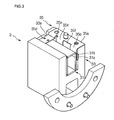
- Fig. 3 is an underbody perspective view of a light tunnel portion in accordance with the invention.
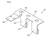
- Fig. 4 is a perspective view showing a plate spring structure supporting a light tunnel in accordance with the invention.
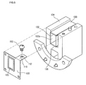
- Fig. 5 is an underbody perspective view in the state that a fixing strip is disassembled in a light tunnel portion in accordance with the second embodiment of the invention
- Fig. 6 is an underbody perspective view in the state that a fixing strip in accordance with the second embodiment of the invention is mounted on a light tunnel portion;
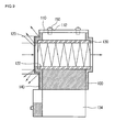
- Fig. 7 is a cross-sectional view taken along the line I-I' in Fig. 6 in accordance with the invention.
- Fig. 8 is a underbody perspective view of a light tunnel in accordance with the third embodiment.
- Fig. 9 is a cross-sectional view taken along the line I-I' in Fig. 8;
- Fig. 10 is a disassembled perspective view of a light tunnel in accordance with the fourth embodiment of the invention.
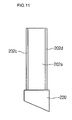
- Fig. 11 is a plan view of a light tunnel in accordance with the fourth embodiment of the invention.
- Fig. 12 is a disassembled perspective view of a light tunnel in accordance with the fifth embodiment of the invention.
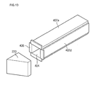
- Fig. 13 is a disassembled perspective view of a light tunnel in accordance with the sixth embodiment of the invention.
- a DLP projection system comprises: a lamp 1 generating a light, a light tunnel portion 3 through which a light generated from the lamp 1 is transmitted; a color wheel 4 where a white light transmitted through the light tunnel portion 3 is divided into RGB; a condensing lens 5 concentrating a light passing through the color wheel 4; a prism 6 where a light passing through the condensing lens 5 is reflected; a DMD 7 focusing a light reflected on the prism 6 to the screen; and a projection lens 8 enlarging a light reflected from the DMD 7.
- the light tunnel portion 3 is formed to transmit a light generated from the lamp 1 to behave as a uniform surface light source.
- the strong light generated from the lamp 1 includes ultraviolet radiation and affects the light tunnel portion 3, ultraviolet radiation is filtered out by the ultraviolet radiation filter 2 before the light is impinged by the light tunnel portion 3.
- the light tunnel portion 3 has mirrors as reflection panels having a reflection plate at the inner sides of a hollow square pillar shape, and light impinged from the lamp 1 becomes a uniform surface light source to irradiate a color wheel 4.
- the light tunnel portion 3 consists of a holder with a predetermined shape (refer to 33 in Fig. 3), a plurality of mirrors placed in the holder 33 and a plurality of supporting members supporting the mirror.
- the holder is provided with a groove drilled inwardly so that a plurality of mirrors are positioned to have a relatively specific structure, and the supporting member makes that relative positions of a mirror can be supported each other.
- an inner portion of a light tunnel provided by the mirror is called a reflection panel.
- the supporting member can be classified in accordance with a position supporting a reflection panel, a shape and a method, and comprises: a first supporting member provided to an end of a reflection panel extended long in accordance with a proceeding direction of a light to fix a relative position of a plurality of reflection panels; a second supporting member supporting a body portion of the reflection panel to fix a relative position of the reflection panel; and a third supporting member connecting contact portions of the relative reflection panel to relatively fix.
- the various embodiments described below may be modified into various shapes in accordance with the various methods employing the supporting members.
- the first embodiment is focused on seizing a body portion of a reflection to improve a structure of a second supporting member fixing a relative position of a reflection panel.
- the light tunnel portion 3 consists of a light tunnel 31, a holder 33 and a plate spring 35.
- the light tunnel 31 is manufactured to have an empty square pillar with four reflection panels 31a, each provided with a mirror, and forms an uniform surface light source such that light impinged from a lamp 1 is reflected/refracted by a reflection panel.
- both ends are supported by the bonding portion 31b, more particularly, it is desirable that an end and the other end are crossed to form a bonding portion 31b so that lamp light transmitted through the light tunnel 31 is not let out through an opening generated at the ends of the reflection panel 31a.
- the holder 33 forms a "U" shaped-insertion groove 33a so that the light tunnel 31 is inserted, and is installed to an optic engine base of a DLP projection system. (Refer to 9 in Fig. 2)
- the plate spring 35 is configured to be fixed to an upper side of the holder 33 to exert pressure on both the side surface and the upper surface of the light tunnel 31 in the insertion hole 33a, and the detailed configuration is as below.
- the plate spring 35 comprises: a holder fixing portion 35a connected with an upper end of a side of the reflection panel insertion hole 33a, a first side plate supporting portion 35b of which a proper path is downwardly curved into an insertion hole 33a from an end of the holder fixing portion 35a to curve a part of an end to an upper side to force an elastic force with respect to a sidewall of an insertion wall, a second side plate supporting portion 35c curvedly formed at a point separated from the first side plate supporting portion 35b to have the same shape as the first side plate supporting portion 35b, and an upper plate supporting portion 35d where a proper path is vertically curved into an insertion hole 33a at the point separated from the second side plate supporting portion 35c and horizontally curved again so as to pressurized the reflection panel 31a of the light tunnel 31.
- the reflection panels 31a having a reflection mirror reflecting a light form a bonding portion 31b bonded by an adhesive to configure a light tunnel 31 with a square light shape.
- the bonding portion 31b is connected with the reflection panel 31a to form a third supporting member.
- the light tunnel 31 passes through a hardening process and is inserted into the reflection panel insertion hole 33a of the holder 33a, and the holder 33 is in the state that an optic axis is arranged to an optic engine base.
- An insertion hole 33a of the holder 33 is manufactured to have a "U" shape so that the light tunnel 31 is positioned at a side edge of the insertion hole 33a so that pressure is applied to a light tunnel 31 by the plate spring 35 at an upper portion so that pressure is applied to a side surface of the light tunnel 31 in a sideways direction.
- the plate spring 35 is configured to be attachable/detachable using additional screw members at a sidewall of the insertion hole 33a.
- the first and the second side plate supporting portions 35b an 35c are fixedly inserted at an interval between a sidewall surface (shown as a right surface in Fig. 3) of a light tunnel and a sidewall of the insertion hole 33a.
- a reflection panel 31a at an upper portion of a light tunnel 31 is mechanically biased downwardly by the upper plate supporting portion 35d curvedly formed at a point at a proper distance from the second side plate supporting portion 35c.
- first and the second side plate supporting portions 35b and 35c are manufactured to be perpendicular to the upper supporting portion 35d, thereby maintaining a corner portion being the weakest portion of a thermal modification to have a stable shape in spite of a high temperature.
- the plate spring 35 applies pressure to the light tunnel 31, and the plate spring 35 is provided with a perpendicular shape, therefore the plate spring 35 applies pressure to the light tunnel 31 with the original perpendicular shape and a corner portion of the light tunnel 31 maintains the originally provided perpendicular shape without any modifications.
- a hole drilling portion 35e is formed with a proper depth at the holder fixing portion 35a between the second side plate supporting portion 35c and the upper plate supporting portion 35d in order to prevent a stress between the upper plate supporting portion 35e and the second side plate supporting portion 35c from being transmitted.
- a hole drilling portion 35f may be formed between the first side plate supporting portion 35b and the second side plate supporting portion 35c for the same reason.
- the hole drilling portions 35e and 35f are formed so that the first side plate supporting portion 35b, the second side plate supporting portion 35c and the upper plate supporting portion 35d have an additional elastic force to apply pressure to each corresponding surface of light tunnel 31.
- the plate spring 35 can apply pressure to the light tunnel 31 in not only a right and left direction but also a up and down direction as the second supporting member supporting a body of the light tunnel 31. Furthermore, pressure can be applied to the light tunnel 31 with a uniform pressurizing force, and the light tunnel 31 can be maintained at a corner portion where temperature changes the most or a portion where a bonding portion is provided.
- the light tunnel can provide a uniform and safe surface light source at a state that modifications are not made even though it is used for a long time by a plate spring having a shape and a structure.
- a plate spring having a shape and a structure.
- it is advantageous to improve an entire image quality and to improve the reliability of a product.
- the configuration supports the light tunnel by the third supporting member where the contact portions contact each other between the reflection panels constituting the light tunnel and the second supporting member supporting a body of the light tunnel.
- a configuration of a first supporting member supporting an end of a light tunnel and a configuration of a light tunnel operating at a high temperature will be described in detail in the embodiments below. It is apparent that the first supporting portion suggested below can be applicable in an embodiment related with the second supporting member and the third member suggested in the first embodiment.
- a light tunnel portion of a DLP projection system includes: a light tunnel 130; a holder 134 to which the light tunnel is mounted to be fixed to an optical engine base; and a fixing strip 100 shielding a light impinged through the other portions except a light tunnel 130 out of a light impinged to the light tunnel 130.
- the light tunnel forms a reflection panel 132 where a mirror having a reflection surface 132a is formed in order to make light projected in the light tunnel reflected/refracted into a uniform surface light source.
- the size of the reflection panel 132 forms a very small shape with a length of 30mm, a width of 6.2mm, a height of 5.2mm and a thickness of 0.5mm.
- the light tunnel 130 includes the reflection panel 132 at four sides so that a reflection surface 132a of the reflection panel 132 is formed at the inner four sides, and an end between the reflection panels is bonded to have an empty square pillar shape.
- an incidence portion for impinging a light irradiated in the lamp and an emitting portion where a light entered the incidence portion is refracted on the reflection surface to be projected to a color wheel are formed.
- a holder 134 is included to mount the light tunnel 130 to an optic engine base 9 and the holder 134 includes an arrival surface 136 with a concave hole so that the light tunnel 130 is safely supported.
- An incidence portion where a light is impinged to a light tunnel 130 to fix the light tunnel 130 to a holder 134 includes a fixing strip 100, and the fixing strip 100 is closely adhered to a front surface of the holder 134 to which the light tunnel 130 arrives.
- the fixing strip 100 is formed to have a wider area than at an outer side of the light tunnel 130, and an incidence opening 120 is formed to the fixing strip 100 to guide a front portion of a light tunnel 130.
- a curved extended strip 110 is extended from the fixing strip 100 to a side of a holder 134 to fix the fixing strip 100 and the holder 134 by a connecting member 150.
- the connecting member 150 is inserted in a screw hole (refer to 112 in Fig. 7) of a holder 134.
- a curved surface (refer to 122 in Fig. 7) is included in an incidence opening 120 equivalent to an external shape of a light tunnel 130 to the fixing strip 100, and a front portion of a light tunnel 130 may be insertedly supported in the incidence opening 120.
- a fixing strip 100 is included on a front surface, or an incidence portion.
- the fixing strip 100 includes an incidence opening 120 having a shape corresponding to an external shape of a light tunnel 130 so that light impinged from the lamp is impinged to the inner portion of a light tunnel 130 and shields light impinged from the outside of the light tunnel 130. Therefore, light impinged from the outside of light tunnel 130, but not used, can prevent temperature from rising more or less.
- the light tunnel 130 contacts a fixing strip 100 multilaterally to transmit heat of the light tunnel 130 heated by light of high temperature to the fixing strip 100. Furthermore, since a body of the fixing strip 100 and an extending strip 110 of the fixing strip 100 are closely adhered to the holder 134, heat of the light tunnel 130 is transmitted to the holder 134 through the fixing strip 100 and internal heat of the light tunnel 130 is rapidly converged to the outside. Due to this, it is advantageous that the temperature of the light tunnel 130 is uniformly distributed and the thermal burden is decreased due to an unequal heat of each part configuring the light tunnel.
- an ultraviolet radiation cutoff layer shielding ultraviolet radiation may be further included.
- the ultraviolet radiation cutoff layer shields ultraviolet radiation of light impinged to a fixing strip 100 to prevent the fixing strip 100 from being heated.
- the structure of a light tunnel is more firmly strengthened by the first supporting member supporting an end of the light tunnel, unnecessary light which is not impinged into the inside of a light tunnel and which would otherwise elevate the temperature of the light tunnel is shielded to rapidly emit internal heat of the light tunnel through a fixing strip and prevent an unequal heating of the light tunnel.
- the intensity of a light tunnel is increased and a radiative function is rapidly performed.
- the third embodiment describes an arrangement in which a fixing strip included at the front of the light tunnel in the second embodiment is included at the rear of a light tunnel, and heat of a light tunnel is rapidly emitted forwardly and backwardly from the light tunnel through a fixing strip.
- the light tunnel 130 arrives at an arrival surface 136 of a holder 134, a fixing strip 100 is extended to the front surface and the rear surface where a light is impinged and emitted, respectively, in order to fix the light tunnel 130 to the holder 134.
- the fixing strip 100 is closely adhered to a front surface and a rear surface of the holder 134 where a light tunnel 130 is mounted so that emitting heat is softly performed and a light tunnel 130 is firmly supported by a fixing strip 100.
- the fixing strip 100 is formed to have a larger width than the width of the external part, and a front portion and a rear portion of a light tunnel 130 is insertedly supported with a regular width at the fixing strip 100 to form an incidence opening 120 identical to the end.
- the incidence opening 120 has a curved surface 122 formed to be insertedly supported outwardly of the light tunnel 130, so that an inner surface of the fixing strip 100 is equal to the outer surface of the light tunnel 130.
- a fixing strip 100 on the front surface and an extending strip 110 connecting the fixing strip 100 at the rear surface is fixed to the holder 134 by a connecting member 150 at a side of the holder 134 and a screw hole 112.
- a fixing strip 100 comprised on the front surface of the light tunnel 130 may be further provided with an ultraviolet radiation cutoff layer 140.
- the biggest reason of raising temperature is based on ultraviolet radiation out of light impinged to a light tunnel 130 from a lamp.
- Ultraviolet radiation which is not filtered by an ultraviolet radiation cutoff filter between a lamp and a light tunnel 130 but included in a light impinged to the light tunnel 130 is filtered again by an ultraviolet radiation cutoff layer 140 of a fixing strip 100 included on a front surface of the light tunnel 130 to inhibit a temperature in the light tunnel from rising.
- the ultraviolet radiation cutoff layer 140 is provided to an opening of the incidence of the light tunnel 130.
- ultraviolet radiation impinged by the ultraviolet cutoff layer 140 is shielded in the holder 134, ultraviolet radiation included in the incident light does not act as a heating source with respect to the holder 134. Therefore, it is advantageous to prevent a temperature of the holder 134 and the light tunnel 130 from rising.
- the light tunnel 130 Since the front and the rear of the light tunnel 130 are supported by the first supporting member corresponding to the fixing strip 100, it has the advantage that the light tunnel 130 maintains the structure more firmly. In addition, since ultraviolet radiation is prevented from being impinged to an ultraviolet radiation cutoff layer, it has the advantage that a temperature of a holder and a light tunnel is prevented from rising.
- a first supporting member supporting a front portion and a rear portion of a light tunnel has a structure supporting the light tunnel as an additional arrangement.
- Other embodiments improving problems in the previously-described embodiments now will be described in further embodiments.
- the following embodiment is the same as the embodiment described above in many aspects, but the configuration of the first supporting member supporting a front and a rear of a light tunnel is different.
- a light tunnel is provided with a reflection panel 202a-202d, referred to as 2020, hereinafter) having a reflection surface 204, and an ultraviolet radiation filter 220 is further fixed at the front of the reflection panel202.
- the ultraviolet radiation filter 220 is essentially the same as an ultraviolet radiation filter 2 as described above in Fig. 1, and is a component filtering ultraviolet radiation in the light generated by a lamp to inhibit the temperature of the light tunnel from rising.
- the ultraviolet radiation filter 220 is fixed at the front portion of the light tunnel to improve the strength of the light tunnel.
- the ultraviolet radiation filter 220 is formed to provide reinforcement, as strength is weakened by the first supporting member by the contact with the reflection panel 202.
- the ultraviolet radiation filter 220 is used to shield ultraviolet radiation used as suggested in Fig. 1 with a purpose of reinforcing the strength of a light tunnel, it does not constitute an additionally necessary component to reinforce the strength of a light tunnel.
- the ultraviolet radiation filter 220 has a prism shape so that ultraviolet radiation is not impinged to a light tunnel, especially, an incidence portion placed at the bottom surface with the prism shape and at the front portion of the light tunnel is bondedly supported to maintain the light tunnel more stably.
- the upper reflection panel 202a and the lower reflection panel 202b and the left reflection panel 202c and the right reflection panel 202d are entirely connected on the inner surface of the ultraviolet filter 220, embodiments of the present invention are advantageous in that the strength of a light tunnel is increased.
- a role of the first supporting member supporting an end of a light tunnel is performed by an ultraviolet radiation filter required in a DLP projection system, and embodiments of the present invention are advantageous in that no additional items are required in order to increase the strength of a light tunnel.
- Embodiments of the present invention may have a shortcoming in that the manufacturing process can become complicated in a case that the light tunnel is bonded to the ultraviolet radiation filter by an adhesive, and other embodiments will be described in order to overcome the problem.
- an ultraviolet filter 320 is inserted at an end of the light tunnel.
- a depressed fixing hole 324 is formed on the corresponding surface of the ultraviolet radiation filter 320 contact with the light tunnel to be adjusted to a horizontal and a vertical lengths, and an incidence portion being a front portion of the light tunnel is fixedly inserted in the inside of the fixing hole 324.
- the fixing hole 324 formed on the ultraviolet ray filter 320 has a reflection filter 202 so that light projected in the lamp is not let out. It is natural that a light tunnel maintains an original shape more firmly by the present embodiment.
- an extension portion 406 is formed to extend a contact surface at the front portion of the light tunnel, in other words, at the front portion of a reflection panel 402 bonded to an ultraviolet filter 220.
- the extension portion 406 is formed on the reflection panel 402
- an area of a light tunnel contacting with the ultraviolet radiation filter 220 increases, a wider and more stable supporting area can be secured and the fixing the ultraviolet radiation filter 220 with a light tunnel becomes more firm.
- the strength of a light tunnel in a DLP project system in accordance with the present invention is improved, a radiative function of a light tunnel is effectively performed, manufacture is conveniently performed, cost becomes low, capability of surface light is improved by a light tunnel, and a system is stably operated.
Landscapes
- Physics & Mathematics (AREA)
- General Physics & Mathematics (AREA)
- Engineering & Computer Science (AREA)
- Multimedia (AREA)
- Signal Processing (AREA)
- Optics & Photonics (AREA)
- Projection Apparatus (AREA)
- Non-Portable Lighting Devices Or Systems Thereof (AREA)
Applications Claiming Priority (3)
| Application Number | Priority Date | Filing Date | Title |
|---|---|---|---|
| KR1020050003124A KR100693530B1 (ko) | 2005-01-13 | 2005-01-13 | 디엘피 프로젝션 텔레비전의 라이트 터널구조 |
| KR1020050038170A KR100743291B1 (ko) | 2005-05-06 | 2005-05-06 | 디엘피 프로젝션 텔레비전의 라이트 터널고정구조 |
| KR1020050038824A KR100727152B1 (ko) | 2005-05-10 | 2005-05-10 | 디엘피 프로젝션 텔레비전의 라이트 터널고정 구조 |
Publications (2)
| Publication Number | Publication Date |
|---|---|
| EP1681876A2 true EP1681876A2 (fr) | 2006-07-19 |
| EP1681876A3 EP1681876A3 (fr) | 2008-11-05 |
Family
ID=35789059
Family Applications (1)
| Application Number | Title | Priority Date | Filing Date |
|---|---|---|---|
| EP05257557A Withdrawn EP1681876A3 (fr) | 2005-01-13 | 2005-12-08 | Intégrateur de lumière pour projecteur DLP |
Country Status (2)
| Country | Link |
|---|---|
| US (1) | US7566135B2 (fr) |
| EP (1) | EP1681876A3 (fr) |
Cited By (1)
| Publication number | Priority date | Publication date | Assignee | Title |
|---|---|---|---|---|
| EP2816405A3 (fr) * | 2013-06-10 | 2015-08-19 | Ricoh Company Ltd. | Appareil de projection d'images avec couvre-poussière |
Families Citing this family (7)
| Publication number | Priority date | Publication date | Assignee | Title |
|---|---|---|---|---|
| KR100692523B1 (ko) * | 2005-04-06 | 2007-03-09 | 삼성전자주식회사 | 프로젝션 시스템용 광학 조립체 |
| JP2007256337A (ja) * | 2006-03-20 | 2007-10-04 | Funai Electric Co Ltd | プロジェクタ |
| EP2407825A1 (fr) | 2010-07-08 | 2012-01-18 | Koninklijke Philips Electronics N.V. | Système de projection avec source de lumière semi-conducteur et matériau luminescent |
| EP2407826A1 (fr) | 2010-07-08 | 2012-01-18 | Koninklijke Philips Electronics N.V. | Système de projection avec source de lumière semi-conducteur et matériau luminescent |
| CN104914543B (zh) * | 2014-03-11 | 2017-08-25 | 中强光电股份有限公司 | 光学元件固定装置及使用其之投影设备 |
| US10481477B2 (en) * | 2016-01-08 | 2019-11-19 | Maxell, Ltd. | Projector apparatus |
| JP7505512B2 (ja) * | 2022-01-25 | 2024-06-25 | セイコーエプソン株式会社 | 光源装置およびプロジェクター |
Family Cites Families (15)
| Publication number | Priority date | Publication date | Assignee | Title |
|---|---|---|---|---|
| KR200187156Y1 (ko) | 1997-12-08 | 2000-07-01 | 윤종용 | 프로젝터용 스크램블러 고정 구조체 |
| KR200187157Y1 (ko) | 1997-12-08 | 2000-07-01 | 윤종용 | 프로젝터용 스크램블러 고정 구조체 |
| JP2000043603A (ja) | 1998-07-29 | 2000-02-15 | Tsuda Industries Co Ltd | 変速操作機構のエネルギー吸収装置 |
| KR100335437B1 (ko) | 1999-03-15 | 2002-05-04 | 윤종용 | 반사형 프로젝트장치 |
| US6422719B1 (en) | 2000-10-10 | 2002-07-23 | Coretronic Corporation | Heat source shielding device of projecting apparatus |
| JP3515066B2 (ja) * | 2000-10-26 | 2004-04-05 | 三菱電機株式会社 | 映像表示装置 |
| US6773118B2 (en) | 2001-09-20 | 2004-08-10 | Benq Corporation | Apparatus for positioning and adjusting a light pipe |
| CN1185541C (zh) | 2001-10-09 | 2005-01-19 | 明基电通股份有限公司 | 光导管的定位及调整装置 |
| JP2003202523A (ja) | 2001-11-02 | 2003-07-18 | Nec Viewtechnology Ltd | 偏光ユニット、該偏光ユニットを用いた偏光照明装置及び該偏光照明装置を用いた投写型表示装置 |
| US6837608B2 (en) * | 2001-11-23 | 2005-01-04 | Benq Corporation | Heat-sinking apparatus for light pipe |
| US6844993B2 (en) | 2002-06-19 | 2005-01-18 | Seiko Epson Corporation | Optical device and projector having the optical device |
| US6883937B2 (en) | 2002-08-23 | 2005-04-26 | Jds Uniphase Corporation | Sequential color recapture light system |
| JP3093005U (ja) | 2002-09-25 | 2003-04-18 | 船井電機株式会社 | 画像表示プロジェクタのライトトンネル構造 |
| JP3743423B2 (ja) * | 2002-12-11 | 2006-02-08 | セイコーエプソン株式会社 | ソリッド型ロッドインテグレータの保持機構 |
| TWM246605U (en) * | 2003-11-24 | 2004-10-11 | Benq Corp | Light pipe bracket |
-
2005
- 2005-11-30 US US11/289,416 patent/US7566135B2/en not_active Expired - Fee Related
- 2005-12-08 EP EP05257557A patent/EP1681876A3/fr not_active Withdrawn
Cited By (2)
| Publication number | Priority date | Publication date | Assignee | Title |
|---|---|---|---|---|
| EP2816405A3 (fr) * | 2013-06-10 | 2015-08-19 | Ricoh Company Ltd. | Appareil de projection d'images avec couvre-poussière |
| US9395607B2 (en) | 2013-06-10 | 2016-07-19 | Ricoh Company, Ltd. | Image projection apparatus including a shield |
Also Published As
| Publication number | Publication date |
|---|---|
| US7566135B2 (en) | 2009-07-28 |
| US20060152689A1 (en) | 2006-07-13 |
| EP1681876A3 (fr) | 2008-11-05 |
Similar Documents
| Publication | Publication Date | Title |
|---|---|---|
| JP5611490B1 (ja) | 投影装置 | |
| US6185047B1 (en) | Image projection system packaged to operate lying flat with a very low profile | |
| US8057084B2 (en) | Side-view type light emitting device and optical device including the same | |
| US11371671B2 (en) | Motor vehicle headlamp having a shielding screen for shielding incident solar radiation | |
| JP5311415B2 (ja) | ディスプレイデバイス用のアンビエント照明システム | |
| US10119675B2 (en) | Vehicle lighting fixture with light-shielding member | |
| CN107636502A (zh) | 广角成像定向背光源 | |
| CN104380186A (zh) | 定向背光源中的串扰抑制 | |
| JP2012118382A (ja) | 液晶表示装置 | |
| EP1681876A2 (fr) | Intégrateur de lumière pour projecteur DLP | |
| KR102298248B1 (ko) | 차량 헤드램프용 레이저 모듈 | |
| JP4516622B2 (ja) | 投写型表示装置 | |
| JP6700792B2 (ja) | 光源装置 | |
| JP6952795B2 (ja) | ヘッドアップディスプレイ | |
| CN215416250U (zh) | 投影光机及投影设备 | |
| JP4810354B2 (ja) | 光走査装置及び走査型画像表示装置 | |
| CN215416252U (zh) | 一种挡光件及投影光机 | |
| US8378365B2 (en) | Light emitting diode package and projection apparatus | |
| US20050046806A1 (en) | Illumination system for projector and illumination method thereof | |
| JP5311608B2 (ja) | 映像表示装置 | |
| JP2005037948A (ja) | 投射表示装置 | |
| KR100743291B1 (ko) | 디엘피 프로젝션 텔레비전의 라이트 터널고정구조 | |
| KR20160001856A (ko) | 광원 패키지 및 이를 장착한 백라이트 유닛 | |
| WO2020114631A1 (fr) | Dispositif d'éclairage pour un véhicule à moteur | |
| JP2009276461A (ja) | 画像表示装置 |
Legal Events
| Date | Code | Title | Description |
|---|---|---|---|
| PUAI | Public reference made under article 153(3) epc to a published international application that has entered the european phase |
Free format text: ORIGINAL CODE: 0009012 |
|
| 17P | Request for examination filed |
Effective date: 20051222 |
|
| AK | Designated contracting states |
Kind code of ref document: A2 Designated state(s): AT BE BG CH CY CZ DE DK EE ES FI FR GB GR HU IE IS IT LI LT LU LV MC NL PL PT RO SE SI SK TR |
|
| AX | Request for extension of the european patent |
Extension state: AL BA HR MK YU |
|
| PUAL | Search report despatched |
Free format text: ORIGINAL CODE: 0009013 |
|
| AK | Designated contracting states |
Kind code of ref document: A3 Designated state(s): AT BE BG CH CY CZ DE DK EE ES FI FR GB GR HU IE IS IT LI LT LU LV MC NL PL PT RO SE SI SK TR |
|
| AX | Request for extension of the european patent |
Extension state: AL BA HR MK YU |
|
| RIC1 | Information provided on ipc code assigned before grant |
Ipc: H05K 7/20 20060101ALN20080929BHEP Ipc: G03B 21/14 20060101ALI20080929BHEP Ipc: H04N 9/31 20060101AFI20060222BHEP |
|
| 17Q | First examination report despatched |
Effective date: 20090206 |
|
| AKX | Designation fees paid |
Designated state(s): DE FR GB |
|
| STAA | Information on the status of an ep patent application or granted ep patent |
Free format text: STATUS: THE APPLICATION IS DEEMED TO BE WITHDRAWN |
|
| 18D | Application deemed to be withdrawn |
Effective date: 20120703 |