EP1681900B1 - Mikrofon und Schallverstärkungssystem - Google Patents
Mikrofon und Schallverstärkungssystem Download PDFInfo
- Publication number
- EP1681900B1 EP1681900B1 EP06000488A EP06000488A EP1681900B1 EP 1681900 B1 EP1681900 B1 EP 1681900B1 EP 06000488 A EP06000488 A EP 06000488A EP 06000488 A EP06000488 A EP 06000488A EP 1681900 B1 EP1681900 B1 EP 1681900B1
- Authority
- EP
- European Patent Office
- Prior art keywords
- signal
- microphone
- section
- sound
- simulative
- Prior art date
- Legal status (The legal status is an assumption and is not a legal conclusion. Google has not performed a legal analysis and makes no representation as to the accuracy of the status listed.)
- Expired - Lifetime
Links
Images


Classifications
-
- H—ELECTRICITY
- H04—ELECTRIC COMMUNICATION TECHNIQUE
- H04R—LOUDSPEAKERS, MICROPHONES, GRAMOPHONE PICK-UPS OR LIKE ACOUSTIC ELECTROMECHANICAL TRANSDUCERS; ELECTRIC HEARING AIDS; PUBLIC ADDRESS SYSTEMS
- H04R3/00—Circuits for transducers
- H04R3/02—Circuits for transducers for preventing acoustic reaction, i.e. acoustic oscillatory feedback
Definitions
- the present invention relates to microphones capable of preventing howling, and sound amplification systems suitable for installation in auditoriums, halls, etc. and capable of preventing howling.
- Fig. 11 is a diagram showing the above-mentioned howling canceler.
- Microphone 301 and speaker 304 are installed in a same sound space, such as an auditorium or hall. Sound signal input via the microphone 301 is amplified via a front-end microphone amplifier and then converted into a digital signal y(k) via an A/D converter.
- the signal y(k) is supplied via an adder 302 to an amplifier 303.
- G(z) represents a transfer function of the amplifier 303.
- Signal x(k) output from the amplifier 303 is converted via a D/A converter into an analog signal and then audibly reproduced or sounded through a speaker 304.
- Sound audibly reproduced through the speaker 304 returns (or is fed back) to the microphone 301 via a sound feedback path 305 leading from the speaker 304 to the microphone 301.
- H(z) represents a transfer function of the sound feedback path 305.
- Feedback signal d(k) fed back via the sound feedback path 305, is input to the microphone 301 along with a source sound signal s(k) uttered by a human speaker or the like.
- the microphone 301 converts the input sounds into digital representation and outputs the converted result as a signal y(k).
- a closed loop is formed by the microphone 301, amplifier 303, speaker 304, sound feedback path 305 and microphone 301. If the gain of the closed loop exceeds one, the feedback signal d(k) is enhanced to produce unwanted howling.
- the sound amplification apparatus of Fig. 11 includes a howling canceller that comprises a delay circuit 306, adaptive filter 307 and adder 302.
- Delay circuit 306 imparts an output signal x(k) of the amplifier 303 with a delay time ⁇ corresponding to a time delay of the sound feedback circuit 305 and outputs the resultant delayed signal x(k - ⁇ ) to the adaptive filter 307.
- the adaptive filter 307 includes a filter section 307a and a filter coefficient estimation section 307b. The signal x(k - ⁇ ) is input to both the filter section 307a and the filter coefficient estimation section 307b.
- the filter section 307a there is set a filter coefficient such that the signal supplied from the microphone 301 is attenuated with a transfer function F(z) simulative of the transfer function H(z) of the sound feedback path 305.
- the adaptive filter 307 outputs a signal do(k) obtained by filtering the signal x(k - ⁇ ) with the transfer function F(z) that is simulative of the transfer function H(z) of the sound feedback path 305; therefore, the output signal do(k) is simulative of the feedback signal d(k) re-input from the speaker 304 to the microphone 301 by way of the sound feedback path 305.
- the adder 302 subtracts the signal do(k), which is simulative of the feedback signal d(k), from the signal y(k) input via the microphone 301 (in this case, the signal y(k) is a combination of the sound source signal and feedback signal). As a consequence, the feedback signal d(k) is removed from the input signal so that howling can be canceled out.
- the filter coefficient estimation section 307b successively updates the filter coefficient of the filter section 307a, using an adaptive algorithm and on the basis of the signals x(k - ⁇ ) and e(k), so that the transfer function F(z) approximates the transfer function H(z) of the sound path 305. In this way, it is possible to provide the signal do(k) simulative of the feedback signal d(k) and prevent howling by use of such a signal do(k).
- the amplifier device with the disclosed howling canceler incorporated therein has only one such howling canceler.
- the howling canceler performs howling-canceling operations on a just single signal obtained by combining signals input via all of the microphones. Therefore, the disclosed howling canceler can not separately deal with individual feedback signals to be re-input to the plurality of microphones, so that it is difficult for the disclosed howling canceler to effectively cancel howling.
- US-B1-6,611,600 discloses a circuit for adaptive suppression of acoustic feedback which forms part of a digital hearing aid, comprising a microphone, subtracter, hearing correcting means, receiver, delay element, filter, updating unit, lattice decorrelators and control unit.
- the transmission path is modeled with the feedback characteristic and an adder.
- the first decorrelator decorrelates the echo-compensated input signal and the second decorrelator decorrelates the delayed output signal by using coefficients from the first decorrelator.
- the coefficients of the two filters are calculated by adaptive decorrelation of the echo-compensated input signal. Updating of the filter coefficients mainly takes place where the greatest amplifications occur in the hearing correcting means.
- the fed-back signal components are continuously removed from the input signal.
- the present invention provides an improved microphone, as set forth in claim 1.
- the simulative feedback signal generated by the simulative feedback signal generation section is subtracted from the sound signal collected by the microphone element, and the subtraction result is output as the residual signal.
- the residual signal is given to the amplifier device of the speaker, so that it is possible to eliminate the feedback signal component, generated by the speaker-produced sound entering the microphone element, and thereby cancel howling.
- the separate microphone is provided with its own simulative feedback signal generation section which generates the simulative feedback signal that is simulative of the feedback signal generated by a sound, produced via the speaker, entering (or re-input to) the microphone element and the simulative feedback signal (component) is subtracted from the sound signal picked up by the microphone
- an existing amplifier device having no noise canceller function, can be used as-it as the amplifier device of the speaker in the sound amplification system.
- howling-canceling processing can be performed separately for each of the microphones with characteristics specific to the microphone.
- the simulative feedback signal generation section includes: a delay circuit that delays the residual signal, output by the arithmetic operator, by a given time; and an adaptive filter that generates the simulative feedback signal by filtering a "previous residual signal" delayed by the delay circuit. Further, the adaptive filter updates a filter coefficient on the basis of the previous residual signal delayed by the delay circuit and a current residual signal output by the arithmetic operator. Thus, on the basis of the previous residual signal output from the delay circuit and the current residual signal output from the arithmetic operator, the adaptive filter automatically updates the filter coefficient so as to allow the transfer function of the adaptive filter itself to agree with or approximate the transfer function of the sound path leading from the speaker to the microphone.
- the simulative feedback signal generation section further includes, at a stage preceding the delay circuit, a simulating amplifier filter that simulates a transfer function of the amplifier device of the speaker, and the simulative feedback signal generation section filters the residual signal, output by the arithmetic operator, by means of the simulating amplifier filter and then supplies the thus-filtered residual signal to the delay circuit.
- the simulating amplifier filter simulating the transfer function of the amplifier device of the speaker
- the feedback transfer function (filter coefficient) of the adaptive filter following the simulating amplifier filter can be easily identified and thus the feedback transfer can be simulated accurately and promptly, with the result that occurrence of howling can be reliably prevented.
- the transfer function of the amplifier device of the speaker may be preset assuming an ordinary amplifier device.
- the microphone of the present invention further comprises: a memory storing a plurality of transfer functions that are respectively simulative of characteristics a plurality of types of amplifier devices usable in the speaker; and a selector that selects any one of the transfer functions from the memory and sets the selected transfer function in the simulating amplifier filter.
- the plurality of transfer functions may be prestored assuming different sizes of various amplifier devices, such as those to be used in large and small halls, auditoriums, meeting rooms and karaoke rooms.
- an improved sound amplification system as set forth in claim 4.
- the feedback transfer function (filter coefficient) of the adaptive filter following the simulating amplifier filter can be easily identified and thus the feedback transfer can be simulated accurately and promptly, with the result that occurrence of howling can be reliably prevented.
- the amplifier device further includes a collection section that collects a parameter, such as a gain setting or sound quality adjustment value, set or adjusted by the signal processing circuit, and a transmitter section that transmits to the microphone the parameter collected by the collection section.
- the microphone further includes a receiver section that receives the gain setting or sound quality adjustment value transmitted by the transmitter section, and a setting section that reproduces a transfer function of the amplifier device on the basis of the gain setting or sound quality adjustment value received by the receiver section and then sets the reproduced transfer function in the simulating amplifier filter.
- the transfer function of the amplifier device can be simulated reliably and easily by the simulating amplifier device.
- the amplifier device further includes a measurement section that measures a transfer function of the amplifier device, and a transmitter section that transmits to the microphone data indicative of the transfer function measured by the measurement section.
- the microphone includes a receiver section that receives the data indicative of the transfer function transmitted by the transmitter section, and a setting section that sets the transfer function, represented by the received data, in the simulating amplifier filter.
- the transfer function of the amplifier device can be simulated reliably and easily by the simulating amplifier device.
- the amplifier device further includes: a detector that detects a sound signal level input via the microphone; a signal blockage section that, when the sound signal level detected by the detector is less than a predetermined threshold value, blocks sound signal input from the microphone to the amplifier device and sound signal output from the amplifier device to the speaker; and a measurement signal supply section that, during the blockage, by the signal blockage section, of the sound signal input and output, supplies a predetermined measurement signal to the amplifier device, the measurement signal supply section causing the measurement section to measure a transfer function of the amplifier device in response to the measurement signal supplied.
- the measurement of the transfer function of the amplifier device is performed by the measurement section when the input sound signal level is less than the predetermined threshold value, i.e. when it can be judged that no source sound or the like has been input via the microphone.
- the input and output to and from the amplifier device is blocked, and the predetermined measurement signal, such as white noise, generated within the system is input to the amplifier device, so that the transfer function of the amplifier device is measured with the predetermined measurement signal input to the amplifier device, i.e. in such condition as to facilitate accurate measurement of the transfer function. Consequently, the transfer function of the amplifier device can be measured accurately and reproduced via the microphone.
- the amplifier device further includes the transmitter section that transmits to the microphone the sound signal amplified and/or adjusted in sound quality by the signal processing circuit, and that the microphone receives the transmitted sound signal and the simulative feedback signal generation section generates the simulative feedback signal on the basis of the received signal
- the simulative feedback signal can be generated using the output signal of the amplifier device (i.e. signal readily simulating the signal processing in the amplifier device). Because the transfer function of the amplifier device is accurately reproduced and used by the microphone to generate the simulative feedback signal, the present invention can appropriately cancel unwanted howling.
- the microphone of the present invention can reliably cancel howling even where it is connected to an existing amplifier device. Further, even in the case where a plurality of the microphones are connected to a single amplifier device, the present invention can cancel a feedback sound input to each of the microphones, to thereby reliably cancel howling.
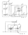
- Fig. 1 is a block diagram of a sound amplification apparatus in accordance with a first embodiment of the present invention.
- the sound amplification apparatus comprises: a microphone 100 including a sound-collecting microphone element 1, A/D converter, howling canceller HC, D/A converter and connecting terminal 3a; an amplifier device 200 including a connecting terminal 3b, microphone amplifier 4, equalizer 5 and power amplifier 6; and a speaker 7.
- a microphone amplifier may be provided between the microphone element 1 and the A/D converter, in which case the amplifier device 200 need not include the microphone amplifier 4.
- the howling canceller HC includes an adder 2 between the A/D converter and the D/A converter, an adaptive filter 9 for supplying a simulative feedback signal to the adder 2, and a delay circuit 8 for delaying a residual signal, output from the adder 2, by a predetermined time and supplying the thus-delayed residual signal to the adaptive filter 9.
- Voice or sound signal output from the microphone element 1 is converted via the A/D converter into a digital signal, delivered via the adder 2 to the D/A converter and then transferred to the connecting terminal 3a as an analog sound signal.
- the connecting terminals 3a and 3b are interconnected to permit transfer of the sound signal.
- the connecting terminals 3a and 3b may be implemented in any suitable form as long as they permit transfer of the sound signal; for example, the connecting terminals 3a and 3b may be a transmitter and receiver, respectively, to transfer the sound signal wirelessly.
- the signal transferred to the connecting terminal 3b is delivered via the microphone amplifier 4 to the equalizer 5 for sound quality adjustment, and then the thus-adjusted signal is transferred via the power amplifier 6 to the speaker 7.
- the speaker 7 produces a sound from the transferred sound signal, i.e. audibly reproduces the transferred sound signal. At least part of the sound audibly produced by the speaker 7 (i.e., "speaker-produced sound") returns to the microphone element 1 to be picked up again by the microphone element 1.
- the howling canceller HC is constructed to simulate, by means of the delay circuit 8 and adaptive filter 9, transfer characteristics of a series of sound transfer paths via which each sound signal input via the microphone element 1 is transferred in the sound space where are installed the amplifier device 200, speaker 7 and microphone 100 and then again input to the microphone element 1.
- the delay circuit 8 is constructed to impart a time delay corresponding to an estimated time delay of a feedback signal returning from the speaker 7 to the microphone element 1.
- the value of the time delay is preset assuming an environment in which the microphone element 1 is used. Alternatively, the time delay may be actually measured in the environment in which the microphone element 1 is used, so as to set the measured value as the value of the time delay.
- the adaptive filter 9 which is a filter for simulating the transfer function of the sound transfer paths, filters the residual signal delayed by the delay circuit 8.
- the thus-filtered signal output from the adaptive filter 9 is supplied to the adder 2 as a simulative feedback signal.
- the adaptive filter 9 includes a filter section 9a and a filter coefficient estimation section 9b, and the delayed residual signal from the delay circuit 8 is supplied to both the filter section 9a and the filter coefficient estimation section 9b.
- the filter section 9a filters the supplied residual signal and supplies the resultant filtered signal to the adder 2.
- the adder 2 subtracts the filtered signal (simulative feedback signal), supplied from the filter section 9a, from the input signal (i.e., picked-up sound signal including the actual feedback signal component) from the microphone element 1. In this manner, the feedback signal component is removed from the picked-up sound signal.
- the filter coefficient estimation section 9b detects a removal error of the feedback signal component on the basis of the previous residual signal delayed by the delay circuit 8 and the current residual signal directly input from the output terminal of the adder 2, and then it automatically updates the transfer function of the filter section 9a so as to allow the simulative feedback signal (hereinafter referred to simply as "simulative signal”) to agree with or approximate the feedback signal.
- the transfer function updating by the filter coefficient estimation section 9b is executed using an adaptive algorithm that may be, for example, an LMS (Least Mean Square) algorithm.
- an LMS Least Mean Square
- Fig. 3 is a diagram explanatory of transfer characteristics of the sound amplification apparatus in accordance with the first embodiment of the present invention.
- the signal y(k) input via the microphone element 1 is supplied to the adder 2.
- the adder 2 subtracts, from the input signal y(k), the output signal of the adaptive filter 9, to thereby output the residual signal e(k).
- the residual signal e(k) is supplied to an amplifying path 51 via the connecting terminals 3a and 3b.
- the amplifying path 51 represents a combination of the signal transfer paths leading from the microphone element 1 to the speaker 7.
- Reference character G(z) represents a transfer function of the amplifying path 51.
- Signal x(k) output from the amplifying path 51 is transferred to the speaker 7, via which it is audibly reproduced or sounded. Sound thus produced via the speaker 7 returns to the microphone element 1 via a sound feedback path 52.
- the sound feedback path 52 is a sound path leading from the speaker 7 to the microphone element 1.
- H(z) represents a transfer function of the sound feedback path 52.
- the feedback signal d(k) returned via the sound feedback path 52 is input to the microphone element 1 along with a sound source signal s(k) generated by a sound source, such as a human speaker, and then the microphone element 1 again outputs these signals as the signal y(k).
- the residual signal e(k) output from the adder 2 is also supplied to the delay circuit 8.
- the delay circuit 8 imparts a time delay to the supplied residual signal e(k) to thereby output the delayed residual signal as a previous residual signal; in this example, the delay circuit 8 imparts the supplied residual signal with a time delay ⁇ corresponding to an estimated time delay of the feedback signal returning from the speaker 7 to the microphone element 1.
- the time-delayed, previous residual signal e(k - ⁇ ) output from the delay circuit 8 is supplied to the adaptive filter 9.
- the adaptive filter 9, as seen in Fig. 2 includes the filter section 9a and filter coefficient estimation section 9b, and the previous delayed residual signal e(k - ⁇ ) output from the delay circuit 8 is supplied to both the filter section 9a and the filter coefficient estimation section 9b.
- the filter section 9a outputs, to the adder 2, the simulative signal do(k) that is simulative of the feedback signal d(k) returning from the speaker 7 to the microphone 1.
- the adder 2 subtracts the simulative signal do(k) from the signal y(k) re-input via the microphone element 1, to thereby output the current residual signal e(k).
- the simulative signal do(k), which is simulative of the feedback signal d(k) is determined in accordance with the transfer function F(z) and on the basis of the previous residual signal e(k - ⁇ ) output from the delay circuit 8.
- the filter coefficient estimation section 9b updates the filter coefficient of the filter section 9a so as to allow the simulative signal do(k), which is simulative of the feedback signal d(k), to agree with or approximate the actual feedback signal d(k), on the basis of the previous residual signal e(k - ⁇ ) output from the delay circuit 8 and the current residual signal e(k) obtained by subtracting the simulative signal do(k) from the signal y(k) re-input via the microphone element 1 to the amplifying path 51 and using the adaptive algorithm.
- an LMS algorithm is used as the adaptive algorithm.
- the delay circuit 8 If the delay circuit 8 is not provided, the signal input to the microphone element 1 will be supplied not only to the adder 2 but also to the adaptive filter 9 with no time delay. Because the adaptive filter 9 updates the filter coefficient in such a manner as to decrease the value of the residual signal e(k), all signals supplied from the microphone element 1 will be canceled in the adder 2 by the output signals from the adaptive filter 9 as the updating of the filter coefficient progresses. For this reason, the delay circuit 8 is essential in order to cancel the feedback signal d(k) with the simulative signal do(k) while preventing cancellation of the sound source signal s(k).
- the microphone 100 equipped with the adaptive filter 9 updates the filter coefficient on the basis of the previous residual signal e(k - ⁇ ) output from the delay circuit 8 and the current residual signal e(k) obtained by subtracting the simulative signal do(k), which is simulative of the feedback signal d(k), from the signal y(k) input via the microphone element 1.
- the gain of the closed loop formed by the microphone element 1 - amplifying path 51 - speaker 7 - sound feedback path 52 - microphone element 1, has exceeded 1 (one) to cause unwanted howling, it is possible to cancel the howling as the time passes.
- the microphone 100 can be connected not only to the amplifier device of Fig. 1 , but also to any other ordinary or conventional amplification apparatus.
- the microphone 100 arranged in the above-described manner can also be used in a manner substantially similar to the conventional microphones; for example, the microphone 100 may take the form of a handy microphone or wireless pin microphone.
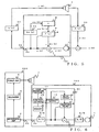
- Fig. 4 is a block diagram of a sound amplification apparatus in accordance with a second embodiment of the present invention.
- the sound amplification apparatus according to the second embodiment includes, in place of the microphone 100 in the first embodiment, a microphone 101 where a reproduction section 10 is connected to the path between the adder 2 and the delay circuit 8.
- the reproduction section 10 is implemented by a digital filter (simulating amplifier filter) that filters the output signal from the adder 2 and outputs the thus-filtered signal to the delay circuit 8. Transfer function of the reproduction section 10 is determined in advance assuming an ordinary sound amplification apparatus or the like. Thus, each signal input to the delay circuit 8 approximates a signal actually transferred to the speaker 7, so that the filter coefficient of the adaptive filter 9 can be easily identified and thus it is possible to promptly deal with occurrence of howling.
- Fig. 5 is a diagram explanatory of transfer characteristics the sound amplification apparatus in accordance with the second embodiment of the present invention.
- the signal y(k) input via the microphone element 1 is supplied to the adder 2.
- the adder 2 subtracts, from the signal y(k), the output signal of the adaptive filter 9, to thereby output the residual signal e(k).
- the residual signal e(k) is supplied to the amplifying path 51 via the connecting terminals 3a and 3b.
- the amplifying path 51 represents a combination of signal transfer paths leading from the microphone element 1 to the speaker 7.
- Reference character G(z) represents a transfer function of the amplifying path 51.
- Signal x(k) output from the amplifying path 51 is transferred to the speaker 7, via which it is audibly reproduced or sounded. Sound thus produced via the speaker 7 returns (i.e., is re-input) to the microphone element 1 via the sound feedback path 52.
- the sound feedback path 52 is a sound path leading from the speaker 7 to the microphone element 1.
- H(z) represents a transfer function of the sound feedback path 52.
- the feedback signal d(k) transferred via the sound feedback path 52 is input to the microphone element 1 along with a sound source signal s(k) generated by a sound source, such as a human speaker, and then the microphone element 1 again outputs these signals as the signal y(k).
- the residual signal e(k) output from the adder 2 is also supplied to the reproduction section 10.
- the reproduction section 10 filters the supplied residual signal e(k) with a predetermined transfer function Go(z) that is preset in view of the transfer function G(z) of the amplifying path 51.
- Output signal xo(k) from the reproduction section 10 is transferred to the delay circuit 8.
- the delay circuit 8 imparts the output signal xo(k) from the reproduction section 10 with a time delay ⁇ corresponding to an estimated time delay of the feedback signal returning to the microphone element 1.
- the time-delayed previous residual signal xo(k - ⁇ ) output from the delay circuit 8 with the time delay ⁇ is supplied to the adaptive filter 9.
- the adaptive filter 9, as shown in Fig. 2 includes the filter section 9a and filter coefficient estimation section 9b, and the previous delayed residual signal xo(k - ⁇ ) output from the delay circuit 8 is supplied to both the filter section 9a and the filter coefficient estimation section 9b.
- the filter section 9a outputs, to the adder 2, the simulative signal do(k) that is simulative of the feedback signal d(k) returning from the speaker 7 to the microphone 1.
- the adder 2 subtracts the simulative signal do(k) from the signal y(k) re-input via the microphone element 1, to thereby output the current residual signal e(k).
- the simulative signal do(k), which is simulative of the feedback signal d(k), is determined on the basis of the signal xo(k - ⁇ ) output from the delay circuit 8 in accordance with the transfer function F(z).
- the filter coefficient estimation section 9b updates the filter coefficient of the filter section 9a so as to allow the simulative signal do(k) to agree with or approximate the actual feedback signal d(k), on the basis of the signal xo(k - ⁇ ) output from the delay circuit 8 and the current residual signal e(k) obtained by subtracting the simulative signal d(k) from the signal y(k) re-input via the microphone element 1 and transferred to the amplifying path 51 and using the adaptive algorithm.
- an LMS algorithm is used as the adaptive algorithm.
- the microphone 101 updates the filter coefficient on the basis of the signal xo(k - ⁇ ), approximate to the signal transferred to the speaker 7, and the residual signal e(k) obtained by subtracting the simulative signal do(k), simulative of the feedback signal d(k), from the signal y(k) input via the microphone element 1 and delivered to the amplifying path 51.
- the microphone 101 too can be connected not only to the amplifier device 200 of Fig. 4 , but also to any other ordinary or conventional amplifier device.
- Fig. 6 is a block diagram showing a modification of the second embodiment of the present invention.
- the microphone 102 is similar to the microphone 101 of the second embodiment in that the reproduction section 10 is connected to the path leading from the microphone 1 to the delay circuit 8, but different therefrom in that it further includes a user operation section 11, control section 12 and memory 13.
- the memory 13 has a plurality of different transfer functions stored therein.
- the control section 12 can change the transfer function of the reproduction section 10 by reading out any one of the transfer functions from the memory 13.
- the user operation section 11 is operable by the user to instruct switching of the transfer function.
- the control section 12 switches the transfer function of the reproduction section 10 to the transfer function designated by the user via the user operation section 11.
- the plurality of transfer functions are prestored in the memory 13 assuming various possible amplifier devices, such as those to be used in large and small halls, auditoriums, karaoke rooms, etc.
- the user may freely select from among the above-mentioned preset conditions in accordance with an environment where the microphone 102 is used. In this way, each signal supplied to the delay circuit 8 can approximate the signal transferred to the speaker 7, so that howling can be canceled more accurately and promptly.
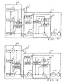
- Fig. 7 is a block diagram of a sound amplification apparatus in accordance with a third embodiment of the present invention.
- the sound amplification apparatus according to the third embodiment includes, in place of the microphone 100 in the first embodiment, a microphone 103 where the reproduction section 10 is connected to the path leading from the microphone element 1 to the delay circuit 8 and which includes the control section 12 and receiver section 14.
- the sound amplification apparatus of Fig. 7 further includes, in place of the amplifier device 200, an amplifier device 201 in which a parameter collecting section 15 is connected to the microphone amplifier 4, equalizer 5 and power amplifier 6 and which also has a transmitter section 16 connected to the parameter collecting section 15.
- the parameter collecting section 15 collects parameter information, such as gain and equalizing settings, of the microphone amplifier 4, equalizer 5 and power amplifier 6.
- the transmitter section 16 is capable of transferring the parameter information, collected by the parameter collecting section 15, to the receiver section 14 of the microphone 103.
- the transfer of the parameter information from the transmitter section 16 to the receiver section 14 may be carried out either by wireless communication or by wired communication.
- the connecting terminals 3a and 3b are interconnected through a wired communication unit
- the parameter information may be transmitted via a cable installed between the connecting terminals 3a and 3b after being modulated with a frequency sufficiently higher than the audio frequencies.
- the wireless communication unit may be constructed as a bidirectional unit to allow the parameter information to be transmitted from the amplifier device 201 to the microphone 103.
- control section 12 reproduces the transfer function of the amplifier device 201 on the basis of the parameter information received via the receiver section 14, such as the gain and equalizing settings, of the microphone amplifier 4, equalizer 5 and power amplifier 6, sets the reproduced transfer function in the reproduction section 10.
- the reproduction section 10 filters the output signal of the adder 2 with the set transfer function and transfers the filtered signal to the delay circuit 8. In this way, each signal supplied to the delay circuit 8 can be extremely approximate to the signal actually transferred to the speaker 7, so that howling can be canceled more accurately and promptly.
- Fig. 8 is a block diagram showing a modification A of the third embodiment of the present invention.
- the modified sound amplification apparatus of Fig. 8 includes the microphone 103, amplifier device 202 where a transfer function measurement section 17 is connected not only to the transfer path leading from the connecting terminal 3b to the microphone amplifier 4 but also to the transfer path leading from the power amplifier 6 to the speaker 7.
- the transfer function measurement section 17 receives the signal transferred over the transfer path leading from the connecting terminal 3b to the microphone amplifier 4 and the signal transferred over the transfer path leading from the power amplifier 6 to the speaker 7, and then, on the basis of a difference in characteristic between these received signals, it measures a transfer function of the transfer path leading from the power amplifier 6 to the speaker 7.
- the thus-measured transfer function is transferred from the connecting terminal 3b to the receiver section 14 of the microphone 103.
- the transfer of the transfer function from the transmitter section 16 to the receiver section 14 may be carried out either by wireless communication or by wired communication.
- the control section 12 sets the transfer function, received by the receiver section 14, in the reproduction section 10.
- the reproduction section 10 filters the output signal of the adder 2 with the set transfer function and transfers the filtered signal to the delay circuit 8.
- the input signal can be filtered with the actually-measured transfer function without arithmetic operations being performed to reproduce the transfer function.
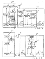
- Fig. 9 is a block diagram showing a modification B of the sound amplification apparatus according to the third embodiment of the present invention.
- the amplifier device 203 includes a noise gate 18a connected between the connecting terminal 3b and the microphone amplifier 4, noise gate 18b connected between the power amplifier 6 and the speaker 7, and a noise gate control section 19 connected to the noise gate 18a and noise gate 18b.
- the transfer function measurement section 17 is connected between the noise gate 18a and the microphone amplifier 4 and between the power amplifier 6 and the noise gate 18b.
- the noise gates 18a and 18b each block a corresponding signal in accordance with an instruction given by the noise gate control section 19. While the noise gates 18a and 18b are blocking the signals, there exists no external input signal in the path leading from the noise gate 18a to the noise gate 18b. Further, the noise gate 18a can output a white noise or other signal in accordance with an instruction given by the noise gate control section 19. Even when the noise gate 18a outputs a white noise or other signal, the noise gate 18b can block the signal, in which case no signal is transferred to the speaker 7.
- the noise gate control section 19 which is connected to the path leading from the connecting terminal 3b to the noise gate 18a, can determine presence/absence of the input signal. If the value of the input signal is equal to or less than a predetermined threshold value, the noise gate control section 19 determines that no signal is currently input to the microphone element 1, in which case the noise gate control section 19 instructs the noise gates 18a and 18b to block the signals. Further, the noise gate control section 19 instructs the noise gate 18a to output a white noise or other signal.
- the transfer function measurement section 17 is connected between the noise gate 18a and the microphone amplifier 4 and between the power amplifier 6 and the noise gate 18b.
- the signal transferred between the noise gate 18a and the microphone amplifier 4 and the signal transferred between the power amplifier 6 and the noise gate 18b can be acquired by the transfer function measurement section 17, and then, on the basis of a difference in characteristic between these acquired signals, the transfer function measurement section 17 can measure a transfer function of the path leading from the noise gate 18a to the noise gate 18b.
- the thus-measured transfer function is transferred from the transmitter section 16 to the receiver section 14 of the microphone 103.
- the transfer of the transfer function from the transmitter section 16 to the receiver section 14 may be carried out either by wireless communication or by wired communication.
- the control section 12 sets the transfer function, received via the receiver section 14, in the reproduction section 10.
- the reproduction section 10 filters the output signal of the adder 2 with the set transfer function and transfers the filtered signal to the delay circuit 8.
- the input signal can be filtered with the actually-measured transfer function without arithmetic operations being performed to reproduce the transfer function.
- Fig. 10 is a block diagram of a sound amplification apparatus in accordance with a fourth embodiment of the present invention.
- the same components as in the first embodiment are indicated by the same reference characters and will not be described in detail here to avoid unnecessary duplication.
- the sound amplification apparatus according to the fourth embodiment includes a microphone 104 provided with a signal receiver section 21 connected to the delay circuit 8, and an amplifier unit 204 provided with a signal transmitter section 20 connected between the power amplifier 6 and the speaker 7.
- the signal transmitter section 20 acquires each signal to be transferred to the speaker 7 and transmits the acquired signal to the signal receiver section 21 of the microphone 104.
- the signal to be transferred to the speaker 7 after having been received by the signal receiver section 21, is converted via the A/D converter into a digital signal, and the thus-converted signal is supplied to the delay circuit 8.
- the signal transfer from the signal transmitter section 20 to the signal receiver section 21 may be carried out either by wireless communication or by wired communication.
- the delay circuit 8 imparts a time delay to each signal to be actually transferred to the speaker 7 and outputs the thus-delayed signal to the adaptive filter 9, so that howling can be canceled more accurately and promptly.
- the sound amplification apparatus which employs the microphone with the adaptive howling canceler incorporated therein, can prevent unwanted howling even where it is connected with an existing amplifier device. Further, by being connected with a sound amplification unit equipped with expansion functions, such as a transfer function measurement section, the sound amplification apparatus of the present invention can cancel howling more accurately and promptly.
- the microphones described above in relation to Figs. 1 - 6 may be used in any desired combination by being connected to an existing amplifier device.
- the microphone of Fig. 1 and the microphone of Fig. 4 may be used in combination by being simultaneously connected to an existing amplifier device.
- the microphones corresponding to the amplifier devices of Figs. 7 - 10 and the microphones of Figs. 1 - 6 may be used in combination.
- the microphone of Fig. 7 and the microphone of Fig. 1 may be used in combination by being connected to the single amplifier device explained above in relation to Fig. 7 .
Landscapes
- Health & Medical Sciences (AREA)
- General Health & Medical Sciences (AREA)
- Otolaryngology (AREA)
- Physics & Mathematics (AREA)
- Engineering & Computer Science (AREA)
- Acoustics & Sound (AREA)
- Signal Processing (AREA)
- Circuit For Audible Band Transducer (AREA)
- Tone Control, Compression And Expansion, Limiting Amplitude (AREA)
- Soundproofing, Sound Blocking, And Sound Damping (AREA)
Claims (9)
- Ein Mikrophon (100, 101, 102, 103, 104), das Folgendes aufweist:ein Mikrophonelement (1);ein simulierender Rückkopplungssignalerzeugungsabschnitt (8, 9), der ein simulierendes Rückkopplungssignal erzeugt, das ein Rückkopplungssignal simuliert, das durch ein Geräusche bzw. einen Ton generiert wird, über einen Lautsprecher (7) erzeugt wird und in das Mikrophonelement (1) eintritt; undeinen arithmetischen Operator bzw. eine Recheneinheit (2), der das simulierende Rückkopplungssignal, das durch den simulierenden Rückkopplungssignalerzeugungsabschnitt (1) erzeugt wird, von einem Tonsignal abzieht, das durch das Mikrophonelement (1) aufgenommen wird, um dadurch ein Ergebnis einer Subtraktion als ein Restsignal auszugeben,wobei das Restsignal, das durch die Recheneinheit (2) ausgegeben wird, an eine Verstärkervorrichtung (200) des Lautsprechers (7) als ein Ausgabesignal des Mikrophons (100, 101, 102, 103, 104) geliefert wird,
wobei der simulierende Rückkopplungssignalerzeugungsabschnitt (8, 9) eine Verzögerungsschaltung (8) zur Verzögerung des Restsignals um eine gegebene Zeit umfasst, welches durch die Recheneinheit ausgegeben wird, sowie einen Anpassungsfilter (9) zum Erzeugen des simulierenden Rückkopplungssignals durch Filtern einer vorherigen Restsignalausgabe von der Verzögerungsschaltung (8), wobei die Recheneinheit (2) das vorherige Restsignal von dem gegenwärtigen Tonsignal subtrahiert, das durch das Mikrophonelement (1) eingefangen wurde, um dadurch ein gegenwärtiges Restsignal auszugeben, und
wobei der simulierende Rückkopplungssignalerzeugungsabschnitt ferner an einer Stufe, die der Verzögerungsschaltung vorgelagert ist, einen simulierenden Verstärkungsfilter (10) umfasst, der eine Übertragungsfunktion der Verstärkervorrichtung (200) des Lautsprechers (7) simuliert, und wobei der simulierende Rückkopplungssignalerzeugungsabschnitt das Restsignal filtert, das von der Recheneinheit ausgegeben wird, und zwar mittels dem simulierenden Verstärkungsfilters (10) und dann das gefilterte Restsignal an die Verzögerungsschaltung (8) liefert. - Mikrophon gemäß Anspruch 1, wobei der Anpassungsfilter (9) einen Filterkoeffizienten aktualisiert, um es zu ermöglichen, dass das simulierende Rückkopplungssignal mit einem tatsächlichen Rückkopplungssignal zusammenpasst, und zwar auf der Basis des vorherigen Restsignals und des gegenwärtigen Restsignals und unter Verwendung eines Anpassungsalgorithmus.
- Mikrophon gemäß Anspruch 1, das ferner Folgendes aufweist:einen Speicher (13) zum Speichern einer Vielzahl von Übertragungsfunktionen, die Nachahmungen von Charakteristiken einer Vielzahl von Typen von Verstärkungsvorrichtungen (200) sind, die in dem Lautsprecher (7) verwendbar sind; undeine Auswahlvorrichtung (11, 12), die irgendeine der Übertragungsfunktionen aus dem Speicher auswählt und die ausgewählte Übertragungsfunktion in dem simulierenden Verstärkungsfilter (10) einstellt.
- Ein Geräusch- bzw. Tonverstärkungssystem, das Folgendes aufweist:ein Mikrophon (103, 104), wie es in einem der vorangehenden Ansprüche definiert ist,eine Verstärkervorrichtung (201, 202, 203, 204) einschließlich einer Signalverarbeitungsschaltung (4, 5), die ein Tonsignal, welches über das Mikrophon (103, 104) eingegeben wird verstärkt und/oder dessen Tonqualität anpasst; undeinen Lautsprecher (7), der das Tonsignal, das durch die Verstärkervorrichtung (201, 202, 203, 204) ausgegeben wird, vernehmbar reproduziert.
- Tonverstärkungssystem gemäß Anspruch 4, wobei die Verstärkungsvorrichtung (201) ferner einen Sammelabschnitt (14) umfasst, der einen Parameter, wie beispielsweise eine Verstärkungseinstellung oder einen Equalizer-Anpassungswert, der durch die Signalverarbeitungsschaltung (4, 5) eingestellt oder angepasst wird, sowie einen Überträger- bzw. Senderabschnitt (16), der die Parameter, die von dem Sammelabschnitt (15) gesammelt werden, an das Mikrophon (103, 104) sendet bzw. überträgt, und
Wobei das Mikrophon (103, 104) ferner einen Empfängerabschnitt (14) aufweist, der die Parameter empfängt, die durch den Senderabschnitt (16) gesendet werden, sowie einen Einstellabschnitt (12), der eine Übertragungsfunktion der Verstärkervorrichtung (201) auf der Basis der Parameter reproduziert, die durch den Empfängerabschnitt (14) empfangen werden und dann die reproduzierte Übertragungsfunktion in dem simulierenden Verstärkerfilter (10) einstellt. - Tonverstärkungssystem gemäß Anspruch 4, wobei die Verstärkervorrichtung (202, 203) ferner einen Messabschnitt (17) umfasst, der eine Übertragungsfunktion der Verstärkervorrichtung (202, 203) misst, sowie einen Senderabschnitt (16), der Daten an das Mikrophon (103, 104) sendet, die eine Anzeige für die Übertragungsfunktion bilden, die durch den Messabschnitt (17) gemessen wird, und
wobei das Mikrophon (103, 104) einen Empfängerabschnitt (14) umfasst, der die Daten empfängt, die eine Anzeige für die Übertragungsfunktion bilden, die von dem Senderabschnitt (16) gesendet werden, sowie einen Einstellabschnitt (12), der die Übertragungsfunktion die durch die empfangenen Daten verkörpert wird, in dem simulierenden Verstärkerfilter (10) einstellt. - Tonverstärkungssystem gemäß Anspruch 6, wobei die Verstärkervorrichtung (203) ferner Folgendes umfasst:einen Detektor (19), der einen Tonsignalpegel detektiert, der über das Mikrophon (103) eingegeben wird;einen Signalblockierungsabschnitt (18a, 18b) der, wenn der Tonsignalpegel, der durch den Detektor detektiert wird, geringer als ein vorbestimmter Grenzwert ist, die Tonsignaleingabe von dem Mikrophon (103) in die Signalverstärkervorrichtung (203) und die Tonsignalausgabe von der Verstärkervorrichtung an den Lautsprecher (7) blockiert; undeinen Messsignallieferabschnitt (18a, 19), der während der Blockade der Tonsignaleingabe und -ausgabe durch den Signalblockierungsabschnitt (18a, 18b), ein vorbestimmtes Messsignal an die Verstärkervorrichtung liefert, wobei der Messsignallieferabschnitt den Messabschnitt (17) veranlasst, eine Übertragungsfunktion der Verstärkervorrichtung (203) ansprechend auf das gelieferte Messsignal zu messen.
- Tonverstärkungssystem gemäß Anspruch 4, wobei die Verstärkervorrichtung (204) ferner einen Senderabschnitt (20) umfasst, der das Tonsignal verstärkt und/oder durch die Signalverarbeitungsschaltung (4, 5) angepasst an das Mikrophon (104) sendet, und
wobei das Mikrophon ferner einen Empfängerabschnitt (21) umfasst, der das Signal empfängt, das durch den Senderabschnitt (20) der Verstärkervorrichtung (204) gesendet wird, wobei der simulierende Rückkopplungssignalerzeugungsabschnitt (8, 9) das simulierende Rückkopplungssignal auf der Basis des Signals erzeugt, das durch den Empfängerabschnitt (21) empfangen wird. - Tonverstärkungssystem gemäß einem der Ansprüche 4 - 8, wobei der Anpassungsfilter (9) einen Filterkoeffizienten aktualisiert, um es zu ermöglichen, dass das simulierende Rückkopplungssignal mit einem tatsächlichen Rückkopplungssignal zusammenpasst, und zwar auf der Basis des vorherigen Restsignals und des gegenwärtigen Restsignals unter Verwendung eines Anpassungsalgorithmus.
Applications Claiming Priority (1)
| Application Number | Priority Date | Filing Date | Title |
|---|---|---|---|
| JP2005004982A JP2006197075A (ja) | 2005-01-12 | 2005-01-12 | マイクロフォンおよび拡声装置 |
Publications (2)
| Publication Number | Publication Date |
|---|---|
| EP1681900A1 EP1681900A1 (de) | 2006-07-19 |
| EP1681900B1 true EP1681900B1 (de) | 2010-04-07 |
Family
ID=36102194
Family Applications (1)
| Application Number | Title | Priority Date | Filing Date |
|---|---|---|---|
| EP06000488A Expired - Lifetime EP1681900B1 (de) | 2005-01-12 | 2006-01-11 | Mikrofon und Schallverstärkungssystem |
Country Status (4)
| Country | Link |
|---|---|
| US (1) | US20060153400A1 (de) |
| EP (1) | EP1681900B1 (de) |
| JP (1) | JP2006197075A (de) |
| DE (1) | DE602006013365D1 (de) |
Families Citing this family (63)
| Publication number | Priority date | Publication date | Assignee | Title |
|---|---|---|---|---|
| US8144892B2 (en) * | 2006-12-18 | 2012-03-27 | The Sapling Company, Inc. Of Huntingdon Valley, Pa. | Audio amplification system |
| JP4974713B2 (ja) * | 2007-03-09 | 2012-07-11 | ヤマハ株式会社 | カラオケ装置 |
| GB2449083B (en) | 2007-05-09 | 2012-04-04 | Wolfson Microelectronics Plc | Cellular phone handset with ambient noise reduction |
| JP5401953B2 (ja) * | 2008-12-05 | 2014-01-29 | ヤマハ株式会社 | 音響システム |
| US9142207B2 (en) | 2010-12-03 | 2015-09-22 | Cirrus Logic, Inc. | Oversight control of an adaptive noise canceler in a personal audio device |
| US8908877B2 (en) | 2010-12-03 | 2014-12-09 | Cirrus Logic, Inc. | Ear-coupling detection and adjustment of adaptive response in noise-canceling in personal audio devices |
| US20120275624A1 (en) * | 2011-04-28 | 2012-11-01 | Szuyu Ho | Energy-saving audio-amplifier control device |
| US8848936B2 (en) | 2011-06-03 | 2014-09-30 | Cirrus Logic, Inc. | Speaker damage prevention in adaptive noise-canceling personal audio devices |
| US9824677B2 (en) | 2011-06-03 | 2017-11-21 | Cirrus Logic, Inc. | Bandlimiting anti-noise in personal audio devices having adaptive noise cancellation (ANC) |
| US8958571B2 (en) * | 2011-06-03 | 2015-02-17 | Cirrus Logic, Inc. | MIC covering detection in personal audio devices |
| US9076431B2 (en) | 2011-06-03 | 2015-07-07 | Cirrus Logic, Inc. | Filter architecture for an adaptive noise canceler in a personal audio device |
| US9318094B2 (en) | 2011-06-03 | 2016-04-19 | Cirrus Logic, Inc. | Adaptive noise canceling architecture for a personal audio device |
| US8948407B2 (en) | 2011-06-03 | 2015-02-03 | Cirrus Logic, Inc. | Bandlimiting anti-noise in personal audio devices having adaptive noise cancellation (ANC) |
| US9214150B2 (en) | 2011-06-03 | 2015-12-15 | Cirrus Logic, Inc. | Continuous adaptation of secondary path adaptive response in noise-canceling personal audio devices |
| US9325821B1 (en) | 2011-09-30 | 2016-04-26 | Cirrus Logic, Inc. | Sidetone management in an adaptive noise canceling (ANC) system including secondary path modeling |
| JP2013102370A (ja) * | 2011-11-09 | 2013-05-23 | Sony Corp | ヘッドホン装置、端末装置、情報送信方法、プログラム、ヘッドホンシステム |
| US9142205B2 (en) | 2012-04-26 | 2015-09-22 | Cirrus Logic, Inc. | Leakage-modeling adaptive noise canceling for earspeakers |
| US9014387B2 (en) | 2012-04-26 | 2015-04-21 | Cirrus Logic, Inc. | Coordinated control of adaptive noise cancellation (ANC) among earspeaker channels |
| US9319781B2 (en) | 2012-05-10 | 2016-04-19 | Cirrus Logic, Inc. | Frequency and direction-dependent ambient sound handling in personal audio devices having adaptive noise cancellation (ANC) |
| US9123321B2 (en) | 2012-05-10 | 2015-09-01 | Cirrus Logic, Inc. | Sequenced adaptation of anti-noise generator response and secondary path response in an adaptive noise canceling system |
| US9076427B2 (en) | 2012-05-10 | 2015-07-07 | Cirrus Logic, Inc. | Error-signal content controlled adaptation of secondary and leakage path models in noise-canceling personal audio devices |
| US9082387B2 (en) | 2012-05-10 | 2015-07-14 | Cirrus Logic, Inc. | Noise burst adaptation of secondary path adaptive response in noise-canceling personal audio devices |
| US9318090B2 (en) | 2012-05-10 | 2016-04-19 | Cirrus Logic, Inc. | Downlink tone detection and adaptation of a secondary path response model in an adaptive noise canceling system |
| JP2015039093A (ja) * | 2012-05-29 | 2015-02-26 | 株式会社東芝 | エコーキャンセラおよびエコーキャンセル方法 |
| US9532139B1 (en) | 2012-09-14 | 2016-12-27 | Cirrus Logic, Inc. | Dual-microphone frequency amplitude response self-calibration |
| US9107010B2 (en) | 2013-02-08 | 2015-08-11 | Cirrus Logic, Inc. | Ambient noise root mean square (RMS) detector |
| US9369798B1 (en) | 2013-03-12 | 2016-06-14 | Cirrus Logic, Inc. | Internal dynamic range control in an adaptive noise cancellation (ANC) system |
| US9106989B2 (en) | 2013-03-13 | 2015-08-11 | Cirrus Logic, Inc. | Adaptive-noise canceling (ANC) effectiveness estimation and correction in a personal audio device |
| US9215749B2 (en) | 2013-03-14 | 2015-12-15 | Cirrus Logic, Inc. | Reducing an acoustic intensity vector with adaptive noise cancellation with two error microphones |
| US9414150B2 (en) | 2013-03-14 | 2016-08-09 | Cirrus Logic, Inc. | Low-latency multi-driver adaptive noise canceling (ANC) system for a personal audio device |
| US9502020B1 (en) | 2013-03-15 | 2016-11-22 | Cirrus Logic, Inc. | Robust adaptive noise canceling (ANC) in a personal audio device |
| US9208771B2 (en) | 2013-03-15 | 2015-12-08 | Cirrus Logic, Inc. | Ambient noise-based adaptation of secondary path adaptive response in noise-canceling personal audio devices |
| US9635480B2 (en) | 2013-03-15 | 2017-04-25 | Cirrus Logic, Inc. | Speaker impedance monitoring |
| US9467776B2 (en) | 2013-03-15 | 2016-10-11 | Cirrus Logic, Inc. | Monitoring of speaker impedance to detect pressure applied between mobile device and ear |
| US10206032B2 (en) | 2013-04-10 | 2019-02-12 | Cirrus Logic, Inc. | Systems and methods for multi-mode adaptive noise cancellation for audio headsets |
| US9066176B2 (en) | 2013-04-15 | 2015-06-23 | Cirrus Logic, Inc. | Systems and methods for adaptive noise cancellation including dynamic bias of coefficients of an adaptive noise cancellation system |
| US9462376B2 (en) | 2013-04-16 | 2016-10-04 | Cirrus Logic, Inc. | Systems and methods for hybrid adaptive noise cancellation |
| US9478210B2 (en) | 2013-04-17 | 2016-10-25 | Cirrus Logic, Inc. | Systems and methods for hybrid adaptive noise cancellation |
| US9460701B2 (en) | 2013-04-17 | 2016-10-04 | Cirrus Logic, Inc. | Systems and methods for adaptive noise cancellation by biasing anti-noise level |
| US9578432B1 (en) | 2013-04-24 | 2017-02-21 | Cirrus Logic, Inc. | Metric and tool to evaluate secondary path design in adaptive noise cancellation systems |
| US9264808B2 (en) | 2013-06-14 | 2016-02-16 | Cirrus Logic, Inc. | Systems and methods for detection and cancellation of narrow-band noise |
| US9392364B1 (en) | 2013-08-15 | 2016-07-12 | Cirrus Logic, Inc. | Virtual microphone for adaptive noise cancellation in personal audio devices |
| US9666176B2 (en) | 2013-09-13 | 2017-05-30 | Cirrus Logic, Inc. | Systems and methods for adaptive noise cancellation by adaptively shaping internal white noise to train a secondary path |
| US9620101B1 (en) | 2013-10-08 | 2017-04-11 | Cirrus Logic, Inc. | Systems and methods for maintaining playback fidelity in an audio system with adaptive noise cancellation |
| US9704472B2 (en) | 2013-12-10 | 2017-07-11 | Cirrus Logic, Inc. | Systems and methods for sharing secondary path information between audio channels in an adaptive noise cancellation system |
| US10219071B2 (en) | 2013-12-10 | 2019-02-26 | Cirrus Logic, Inc. | Systems and methods for bandlimiting anti-noise in personal audio devices having adaptive noise cancellation |
| US10382864B2 (en) | 2013-12-10 | 2019-08-13 | Cirrus Logic, Inc. | Systems and methods for providing adaptive playback equalization in an audio device |
| US9369557B2 (en) | 2014-03-05 | 2016-06-14 | Cirrus Logic, Inc. | Frequency-dependent sidetone calibration |
| US9479860B2 (en) | 2014-03-07 | 2016-10-25 | Cirrus Logic, Inc. | Systems and methods for enhancing performance of audio transducer based on detection of transducer status |
| US9648410B1 (en) | 2014-03-12 | 2017-05-09 | Cirrus Logic, Inc. | Control of audio output of headphone earbuds based on the environment around the headphone earbuds |
| US9319784B2 (en) | 2014-04-14 | 2016-04-19 | Cirrus Logic, Inc. | Frequency-shaped noise-based adaptation of secondary path adaptive response in noise-canceling personal audio devices |
| US9609416B2 (en) | 2014-06-09 | 2017-03-28 | Cirrus Logic, Inc. | Headphone responsive to optical signaling |
| US10181315B2 (en) | 2014-06-13 | 2019-01-15 | Cirrus Logic, Inc. | Systems and methods for selectively enabling and disabling adaptation of an adaptive noise cancellation system |
| US9478212B1 (en) | 2014-09-03 | 2016-10-25 | Cirrus Logic, Inc. | Systems and methods for use of adaptive secondary path estimate to control equalization in an audio device |
| US9552805B2 (en) | 2014-12-19 | 2017-01-24 | Cirrus Logic, Inc. | Systems and methods for performance and stability control for feedback adaptive noise cancellation |
| WO2017029550A1 (en) | 2015-08-20 | 2017-02-23 | Cirrus Logic International Semiconductor Ltd | Feedback adaptive noise cancellation (anc) controller and method having a feedback response partially provided by a fixed-response filter |
| US9578415B1 (en) | 2015-08-21 | 2017-02-21 | Cirrus Logic, Inc. | Hybrid adaptive noise cancellation system with filtered error microphone signal |
| US10013966B2 (en) | 2016-03-15 | 2018-07-03 | Cirrus Logic, Inc. | Systems and methods for adaptive active noise cancellation for multiple-driver personal audio device |
| TWI651971B (zh) * | 2016-04-26 | 2019-02-21 | 宏達國際電子股份有限公司 | 手持式電子裝置、聲音產生系統及其聲音產生的控制方法 |
| JP6197930B2 (ja) * | 2016-09-14 | 2017-09-20 | ソニー株式会社 | 耳孔装着型収音装置、信号処理装置、収音方法 |
| JP6984254B2 (ja) * | 2017-09-08 | 2021-12-17 | ヤマハ株式会社 | カラオケユニット |
| CN113450819B (zh) * | 2021-05-21 | 2024-06-18 | 音科思(深圳)技术有限公司 | 信号处理方法及相关产品 |
| WO2026073138A1 (en) * | 2024-09-30 | 2026-04-02 | The Board Of Trustees Of The Leland Stanford Junior University | Simulated acoustics calibration system, method and applications |
Family Cites Families (5)
| Publication number | Priority date | Publication date | Assignee | Title |
|---|---|---|---|---|
| JPS5630397A (en) * | 1979-08-21 | 1981-03-26 | Yoshio Yamazaki | Additional device for howling prevention |
| GB2147166B (en) * | 1983-09-26 | 1986-11-05 | Graham Potter | Apparatus and method for providing an undistorted output signal from a non-linear device |
| US5774557A (en) * | 1995-07-24 | 1998-06-30 | Slater; Robert Winston | Autotracking microphone squelch for aircraft intercom systems |
| DK0930801T3 (da) * | 1998-01-14 | 2009-02-23 | Bernafon Ag | Kredslöb og fremgangsmåde til adaptiv undertrykkelse af akustisk tilbagekobling |
| DE10140523B4 (de) * | 2001-08-17 | 2005-08-18 | Dietmar Dr. Ruwisch | Vorrichtung zum Feedback Cancelling bei der Ausgabe von Mikrofonsignalen durch Lautsprecher |
-
2005
- 2005-01-12 JP JP2005004982A patent/JP2006197075A/ja active Pending
-
2006
- 2006-01-11 DE DE602006013365T patent/DE602006013365D1/de not_active Expired - Lifetime
- 2006-01-11 US US11/330,549 patent/US20060153400A1/en not_active Abandoned
- 2006-01-11 EP EP06000488A patent/EP1681900B1/de not_active Expired - Lifetime
Also Published As
| Publication number | Publication date |
|---|---|
| EP1681900A1 (de) | 2006-07-19 |
| US20060153400A1 (en) | 2006-07-13 |
| DE602006013365D1 (de) | 2010-05-20 |
| JP2006197075A (ja) | 2006-07-27 |
Similar Documents
| Publication | Publication Date | Title |
|---|---|---|
| EP1681900B1 (de) | Mikrofon und Schallverstärkungssystem | |
| EP2847760B1 (de) | Durch fehlersignalinhalte gesteuerte anpassung von sekundären leckagepfadmodellen in personalisierten audiovorrichtungen mit rauschunterdrückung | |
| US10332502B2 (en) | Noise reducing device, noise reducing method, noise reducing program, and noise reducing audio outputting device | |
| EP2494792B1 (de) | Verfahren und System zur Sprachverbesserung | |
| JP6106164B2 (ja) | ノイズキャンセリングパーソナルオーディオデバイスにおける二次経路適合的応答の連続的適合 | |
| KR101837529B1 (ko) | 방수음 장치 및 방수음 방법 | |
| US8315400B2 (en) | Method and device for acoustic management control of multiple microphones | |
| US10206032B2 (en) | Systems and methods for multi-mode adaptive noise cancellation for audio headsets | |
| US20110150257A1 (en) | Adaptive feedback cancellation based on inserted and/or intrinsic characteristics and matched retrieval | |
| JP4130835B2 (ja) | 音響フィードバック抑制機能付き補聴器 | |
| JP2016218456A (ja) | ノイズ除去音声再生 | |
| US6385176B1 (en) | Communication system based on echo canceler tap profile | |
| JPH10191497A (ja) | ディジタル式補聴器およびフィードバック経路のモデリング方法 | |
| KR20180044324A (ko) | 피드백 적응적 잡음 소거(anc) 제어기 및 고정 응답 필터에 의해 부분적으로 제공되는 피드백 응답을 갖는 방법 | |
| US9020171B2 (en) | Method for control of adaptation of feedback suppression in a hearing aid, and a hearing aid | |
| US20070172080A1 (en) | Acoustic feedback suppression | |
| CN115334400B (zh) | 一种用于对耳机的接近度检测的集成电路及耳机 | |
| US20070206824A1 (en) | Hearing Aid With Anti Feedback System | |
| JP4835151B2 (ja) | オーディオシステム | |
| WO2001054452A1 (en) | Electromagnetic feedback reduction in communication device | |
| JP4400485B2 (ja) | 適応型音場支援装置 | |
| JP2002009677A (ja) | 音響エコーキャンセラー装置 | |
| JP2006245670A (ja) | 適応型音場支援装置 | |
| JPH0832115B2 (ja) | 拡声放送装置の自動音量調整装置 | |
| JP3358463B2 (ja) | 拡声装置 |
Legal Events
| Date | Code | Title | Description |
|---|---|---|---|
| PUAI | Public reference made under article 153(3) epc to a published international application that has entered the european phase |
Free format text: ORIGINAL CODE: 0009012 |
|
| AK | Designated contracting states |
Kind code of ref document: A1 Designated state(s): AT BE BG CH CY CZ DE DK EE ES FI FR GB GR HU IE IS IT LI LT LU LV MC NL PL PT RO SE SI SK TR |
|
| AX | Request for extension of the european patent |
Extension state: AL BA HR MK YU |
|
| 17P | Request for examination filed |
Effective date: 20070119 |
|
| AKX | Designation fees paid |
Designated state(s): DE FR GB |
|
| RAP1 | Party data changed (applicant data changed or rights of an application transferred) |
Owner name: YAMAHA CORPORATION |
|
| 17Q | First examination report despatched |
Effective date: 20080311 |
|
| GRAP | Despatch of communication of intention to grant a patent |
Free format text: ORIGINAL CODE: EPIDOSNIGR1 |
|
| GRAS | Grant fee paid |
Free format text: ORIGINAL CODE: EPIDOSNIGR3 |
|
| GRAA | (expected) grant |
Free format text: ORIGINAL CODE: 0009210 |
|
| AK | Designated contracting states |
Kind code of ref document: B1 Designated state(s): DE FR GB |
|
| REG | Reference to a national code |
Ref country code: GB Ref legal event code: FG4D |
|
| REF | Corresponds to: |
Ref document number: 602006013365 Country of ref document: DE Date of ref document: 20100520 Kind code of ref document: P |
|
| PLBE | No opposition filed within time limit |
Free format text: ORIGINAL CODE: 0009261 |
|
| STAA | Information on the status of an ep patent application or granted ep patent |
Free format text: STATUS: NO OPPOSITION FILED WITHIN TIME LIMIT |
|
| 26N | No opposition filed |
Effective date: 20110110 |
|
| PGFP | Annual fee paid to national office [announced via postgrant information from national office to epo] |
Ref country code: DE Payment date: 20140108 Year of fee payment: 9 |
|
| PGFP | Annual fee paid to national office [announced via postgrant information from national office to epo] |
Ref country code: FR Payment date: 20140108 Year of fee payment: 9 |
|
| PGFP | Annual fee paid to national office [announced via postgrant information from national office to epo] |
Ref country code: GB Payment date: 20140108 Year of fee payment: 9 |
|
| REG | Reference to a national code |
Ref country code: DE Ref legal event code: R119 Ref document number: 602006013365 Country of ref document: DE |
|
| GBPC | Gb: european patent ceased through non-payment of renewal fee |
Effective date: 20150111 |
|
| PG25 | Lapsed in a contracting state [announced via postgrant information from national office to epo] |
Ref country code: DE Free format text: LAPSE BECAUSE OF NON-PAYMENT OF DUE FEES Effective date: 20150801 Ref country code: GB Free format text: LAPSE BECAUSE OF NON-PAYMENT OF DUE FEES Effective date: 20150111 |
|
| REG | Reference to a national code |
Ref country code: FR Ref legal event code: ST Effective date: 20150930 |
|
| PG25 | Lapsed in a contracting state [announced via postgrant information from national office to epo] |
Ref country code: FR Free format text: LAPSE BECAUSE OF NON-PAYMENT OF DUE FEES Effective date: 20150202 |