EP1682802B1 - Soupape servant a commander le passage de fluides, comportant un element multifonctionnel - Google Patents
Soupape servant a commander le passage de fluides, comportant un element multifonctionnel Download PDFInfo
- Publication number
- EP1682802B1 EP1682802B1 EP04802637A EP04802637A EP1682802B1 EP 1682802 B1 EP1682802 B1 EP 1682802B1 EP 04802637 A EP04802637 A EP 04802637A EP 04802637 A EP04802637 A EP 04802637A EP 1682802 B1 EP1682802 B1 EP 1682802B1
- Authority
- EP
- European Patent Office
- Prior art keywords
- valve
- component
- function
- multifunctional component
- multifunctional
- Prior art date
- Legal status (The legal status is an assumption and is not a legal conclusion. Google has not performed a legal analysis and makes no representation as to the accuracy of the status listed.)
- Expired - Lifetime
Links
- 239000012530 fluid Substances 0.000 title claims description 8
- 238000000034 method Methods 0.000 claims description 2
- 238000005245 sintering Methods 0.000 claims description 2
- 239000000843 powder Substances 0.000 description 4
- FIKFLLIUPUVONI-UHFFFAOYSA-N 8-(2-phenylethyl)-1-oxa-3,8-diazaspiro[4.5]decan-2-one;hydrochloride Chemical compound Cl.O1C(=O)NCC11CCN(CCC=2C=CC=CC=2)CC1 FIKFLLIUPUVONI-UHFFFAOYSA-N 0.000 description 2
- 238000010310 metallurgical process Methods 0.000 description 2
- 238000004663 powder metallurgy Methods 0.000 description 2
- 239000000356 contaminant Substances 0.000 description 1
- 238000011109 contamination Methods 0.000 description 1
- 230000001419 dependent effect Effects 0.000 description 1
- 238000011161 development Methods 0.000 description 1
- 230000018109 developmental process Effects 0.000 description 1
- 238000001746 injection moulding Methods 0.000 description 1
- 238000012423 maintenance Methods 0.000 description 1
- 238000004519 manufacturing process Methods 0.000 description 1
- 239000002184 metal Substances 0.000 description 1
- 229910001092 metal group alloy Inorganic materials 0.000 description 1
- 238000007789 sealing Methods 0.000 description 1
Images
Classifications
-
- F—MECHANICAL ENGINEERING; LIGHTING; HEATING; WEAPONS; BLASTING
- F16—ENGINEERING ELEMENTS AND UNITS; GENERAL MEASURES FOR PRODUCING AND MAINTAINING EFFECTIVE FUNCTIONING OF MACHINES OR INSTALLATIONS; THERMAL INSULATION IN GENERAL
- F16K—VALVES; TAPS; COCKS; ACTUATING-FLOATS; DEVICES FOR VENTING OR AERATING
- F16K31/00—Actuating devices; Operating means; Releasing devices
- F16K31/02—Actuating devices; Operating means; Releasing devices electric; magnetic
- F16K31/06—Actuating devices; Operating means; Releasing devices electric; magnetic using a magnet, e.g. diaphragm valves, cutting off by means of a liquid
- F16K31/0644—One-way valve
- F16K31/0655—Lift valves
- F16K31/0658—Armature and valve member being one single element
-
- B—PERFORMING OPERATIONS; TRANSPORTING
- B60—VEHICLES IN GENERAL
- B60T—VEHICLE BRAKE CONTROL SYSTEMS OR PARTS THEREOF; BRAKE CONTROL SYSTEMS OR PARTS THEREOF, IN GENERAL; ARRANGEMENT OF BRAKING ELEMENTS ON VEHICLES IN GENERAL; PORTABLE DEVICES FOR PREVENTING UNWANTED MOVEMENT OF VEHICLES; VEHICLE MODIFICATIONS TO FACILITATE COOLING OF BRAKES
- B60T8/00—Arrangements for adjusting wheel-braking force to meet varying vehicular or ground-surface conditions, e.g. limiting or varying distribution of braking force
- B60T8/32—Arrangements for adjusting wheel-braking force to meet varying vehicular or ground-surface conditions, e.g. limiting or varying distribution of braking force responsive to a speed condition, e.g. acceleration or deceleration
- B60T8/34—Arrangements for adjusting wheel-braking force to meet varying vehicular or ground-surface conditions, e.g. limiting or varying distribution of braking force responsive to a speed condition, e.g. acceleration or deceleration having a fluid pressure regulator responsive to a speed condition
- B60T8/36—Arrangements for adjusting wheel-braking force to meet varying vehicular or ground-surface conditions, e.g. limiting or varying distribution of braking force responsive to a speed condition, e.g. acceleration or deceleration having a fluid pressure regulator responsive to a speed condition including a pilot valve responding to an electromagnetic force
- B60T8/3615—Electromagnetic valves specially adapted for anti-lock brake and traction control systems
- B60T8/363—Electromagnetic valves specially adapted for anti-lock brake and traction control systems in hydraulic systems
Definitions
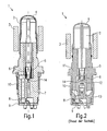
- FIG. 2 shows a known electromagnetic valve according to the prior art.
- the valve 1 comprises an armature 2, which is connected to a designed as a ram actuator and can be moved in a known manner by means of a magnetic coil 3.
- the armature 2 is movable in a known manner within a sleeve 4.
- the sleeve 4 is connected to a valve insert 11, which serves as a guide element for the actuating element 5.
- a return spring 6 returns the actuator 5 to its original position.
- the known valve comprises a valve body 12, in which a passage 14 to be closed or released by the valve is arranged, as well as a plastic insert 13 with a throttle device.
- a valve body 12 in which a passage 14 to be closed or released by the valve is arranged, as well as a plastic insert 13 with a throttle device.
- two filters 9 and 10 are further provided. Via a check valve 8, any overpressure occurring in the valve can be grown become. When de-energized, the valve is constantly open.
- valve 1 A disadvantage of this known valve 1 that the active part of the valve consists of several individual components such as the valve core 11, the valve body 12 and the plastic insert 13. This results in an increased number of parts and a complex assembly. Furthermore, in particular, the use of plastic for the plastic insert 13 in the case of increasing load or over the life lead to damage. This is particularly important because the newer and future hydraulic systems operate in vehicles with ever higher pressures.
- a valve for controlling fluids comprises a component which combines functions of a valve core, valve body and throttle component in a single component.
- the valve according to the invention for controlling fluids with the features of claim 1 has the advantage that it is particularly inexpensive to produce and has only a small number of parts. As a result, the assembly costs for the valve can be reduced, which brings particularly great cost advantages, since it is mass-produced valves. According to the invention this is achieved in that the valve has a multi-functional component, which integrates several components in itself and assumes their functions.
- the multi-function component assumes the function of the valve insert for guiding the actuating element, the function of the valve body in which the opening to be released or to be closed is arranged, and the function of a throttle component.
- the multifunctional component can thus replace several previously used individual components in the valve.
- the multifunctional components also include a function for a check valve, via which any existing overpressure can be reduced.
- the multifunctional component is produced by means of a powder metallurgical process.
- a powder metallurgical process is able to meet even the highest requirements in terms of pressure load. This is not the case with the previously used valves, since these still use plastic components, such as the throttle component.
- valves according to the invention are preferably used in hydraulic systems of vehicles. Particularly preferred valves according to the invention are used in ABS systems and / or ASR systems and / or other Fahrregelungs- or braking systems of a vehicle.
- FIG. 1 shows a valve 1 for controlling fluids according to a preferred embodiment of the invention.
- the valve 1 comprises an armature 2, which in a sleeve 4 by means of energizing a magnetic coil 3 back and forth.
- the armature 2 is connected to an actuating element 5 in the form of a plunger, so that an opening or a passage 14 can be released or closed.
- a return spring 6 provides a provision of the actuating element 5 and the armature 2 in their initial position. To prevent contaminants such as e.g. small metal chips or similar can get into the valve 1, two filters 9 and 10 are still provided.
- the valve 1 according to the invention comprises a multifunctional component 7.
- the multifunctional component 7 several functions are integrated in one component. More specifically, the function of a valve core for guiding the actuator 5, the function of a valve body, in in which the opening to be released or to be closed 14 is formed, and integrates the function of a throttle component.
- the multifunctional component 7 comprises a springless check valve 8, via which a possibly occurring overpressure can be reduced.
- the return spring 6 presses the actuator 5 constantly against the armature 2 and thus keeps the valve open.
- the magnetic coil 3 is energized and the armature thereby pressed against the back of the actuating element 5, whereby the actuating element 5 moves axially against the spring force of the return spring 6 and the passage 14 closes.
- the multi-functional component 7 of the solenoid valve is made by powder metallurgy and has a high load capacity, which is significantly higher than the capacity of plastic parts.
- the necessary complex geometry of the throttle component can be produced while maintaining the necessary tolerance values by the powder metallurgical manufacturing process.
- a multifunctional component 7 produced in this way has increased tightness, since there are fewer sealing surfaces between the individual components of the valve due to the reduced number of parts.
- metal alloys can be used.
- the solenoid valve 1 according to the invention is preferably used in the hydraulic system of an ABS system as a 2/2-way solenoid valve.
Landscapes
- Engineering & Computer Science (AREA)
- Physics & Mathematics (AREA)
- General Engineering & Computer Science (AREA)
- Mechanical Engineering (AREA)
- Electromagnetism (AREA)
- Fluid Mechanics (AREA)
- Transportation (AREA)
- Magnetically Actuated Valves (AREA)
Claims (4)
- Soupape de commande de fluide comprenant un élément de fermeture (5) pour fermer ou libérer un passage (14), un élément de rappel (6) pour rappeler l'élément de fermeture (5) dans sa position de sortie, un induit (2), mobile, déplacé par une bobine d'induit (3) ainsi qu'un composant multifonctionnel (7) assurant la fonction d'un insert de soupape, la fonction d'un corps de soupape et la fonction d'un composant d'étranglement dans un seul composant,
caractérisée en ce que
le composant multifonctionnel (7) est fabriqué par un procédé de métallurgie des poudres et
le composant multifonctionnel (7) assure en outre également la fonction d'un clapet anti-retour (8). - Soupape selon la revendication 1,
caractérisée en ce que
le composant multifonctionnel (7) est fabriqué par frittage. - Soupape selon l'une des revendications précédentes,
caractérisée en ce que
la soupape est appliquée à un système hydraulique de véhicule. - Soupape selon la revendication 3,
caractérisée en ce que
la soupape est utilisée dans un système de frein et/ou dans un système de stabilisation électronique et/ou dans un système de régulation anti-patinage.
Applications Claiming Priority (2)
| Application Number | Priority Date | Filing Date | Title |
|---|---|---|---|
| DE10352003A DE10352003A1 (de) | 2003-11-07 | 2003-11-07 | Ventil zum Steuern von Fluiden mit multifunktionalem Bauteil |
| PCT/DE2004/002365 WO2005045290A1 (fr) | 2003-11-07 | 2004-10-23 | Soupape servant a commander le passage de fluides, comportant un element multifonctionnel |
Publications (2)
| Publication Number | Publication Date |
|---|---|
| EP1682802A1 EP1682802A1 (fr) | 2006-07-26 |
| EP1682802B1 true EP1682802B1 (fr) | 2008-10-08 |
Family
ID=34559448
Family Applications (1)
| Application Number | Title | Priority Date | Filing Date |
|---|---|---|---|
| EP04802637A Expired - Lifetime EP1682802B1 (fr) | 2003-11-07 | 2004-10-23 | Soupape servant a commander le passage de fluides, comportant un element multifonctionnel |
Country Status (5)
| Country | Link |
|---|---|
| US (1) | US20070102659A1 (fr) |
| EP (1) | EP1682802B1 (fr) |
| CN (1) | CN100385160C (fr) |
| DE (2) | DE10352003A1 (fr) |
| WO (1) | WO2005045290A1 (fr) |
Families Citing this family (7)
| Publication number | Priority date | Publication date | Assignee | Title |
|---|---|---|---|---|
| DE102006054185A1 (de) * | 2006-11-16 | 2008-05-21 | Robert Bosch Gmbh | Magnetventil |
| DE102006055831A1 (de) * | 2006-11-27 | 2008-05-29 | Robert Bosch Gmbh | Magnetventil |
| DE102008042731A1 (de) * | 2008-10-10 | 2010-04-15 | Robert Bosch Gmbh | Magnetventil |
| DE102009055346A1 (de) * | 2009-12-29 | 2011-06-30 | Robert Bosch GmbH, 70469 | Magnetventil, Verfahren zur Herstellung eines Magnetventils |
| US20120153199A1 (en) * | 2010-12-20 | 2012-06-21 | Robertshaw Controls Company | Solenoid for a Direct Acting Valve Having Stepped Guide Tube |
| CN102303598A (zh) * | 2011-08-21 | 2012-01-04 | 浙江亚太机电股份有限公司 | 一种带限压阀功能的esp常开阀 |
| DE102021205341A1 (de) | 2021-05-26 | 2022-12-01 | Continental Automotive Technologies GmbH | Elektromagnetventil, insbesondere für schlupfgeregelte Kraftfahrzeugbremsanlagen |
Family Cites Families (20)
| Publication number | Priority date | Publication date | Assignee | Title |
|---|---|---|---|---|
| DE3212977A1 (de) * | 1982-04-07 | 1983-10-13 | Robert Bosch Gmbh, 7000 Stuttgart | Magnetventil |
| DE3924814A1 (de) * | 1988-08-25 | 1990-03-01 | Volkswagen Ag | Elektromagnetisches servoventil |
| DE4035817A1 (de) * | 1990-11-10 | 1992-05-14 | Bosch Gmbh Robert | Elektromagnetbetaetigtes ventil, insbesondere fuer hydraulische bremsanlagen von kraftfahrzeugen |
| DE4217871A1 (de) * | 1992-05-29 | 1993-12-02 | Thomas Magnete Gmbh | Elektromagnet mit mit einer Stange versehenem Anker |
| JP2569208Y2 (ja) * | 1992-10-13 | 1998-04-22 | 株式会社ユニシアジェックス | 電磁弁構造 |
| DE19504246A1 (de) * | 1995-02-09 | 1996-08-14 | Teves Gmbh Alfred | Elektromagnetventil mit Druckbegrenzungsfunktion, insbesondere für hydraulische Kraftfahrzeugbremsanlagen mit Schlupfregelung und/oder automatischem Bremseneingriff zur Fahrdynamikregelung |
| DE19700980A1 (de) * | 1997-01-14 | 1998-07-16 | Teves Gmbh Alfred | Elektromagnetventil |
| JP3882299B2 (ja) * | 1997-12-22 | 2007-02-14 | 株式会社デンソー | 電磁弁一体型膨張弁 |
| WO1999044872A1 (fr) * | 1998-03-03 | 1999-09-10 | Continental Teves Ag & Co. Ohg | Electrovanne |
| US6139598A (en) * | 1998-11-19 | 2000-10-31 | Eaton Corporation | Powdered metal valve seat insert |
| DE19910207A1 (de) * | 1999-03-09 | 2000-09-14 | Bosch Gmbh Robert | Ventil, insbesondere für schlupfgeregelte hydraulische Bremsanlagen von Kraftfahrzeugen |
| EP1194322B1 (fr) * | 1999-06-23 | 2005-06-08 | Continental Teves AG & Co. oHG | Soupape electromagnetique, notamment pour systemes de freinage hydrauliques a antiblocage |
| US6742764B1 (en) * | 1999-08-25 | 2004-06-01 | Continental Teves Ag & Co., Ohg | Electromagnetic valve |
| US6345870B1 (en) * | 1999-10-28 | 2002-02-12 | Kelsey-Hayes Company | Control valve for a hydraulic control unit |
| JP2002043125A (ja) * | 1999-12-09 | 2002-02-08 | Sumitomo Electric Ind Ltd | 電磁アクチュエータ及びこれを用いた内燃機関用弁開閉機構 |
| US6354267B1 (en) * | 2000-03-28 | 2002-03-12 | Borgwarner Inc. | Injection molded throttle body |
| CN2480178Y (zh) * | 2000-12-24 | 2002-03-06 | 傅建中 | 汽车爆胎自动刹车、紧急制动模拟abs功能机构 |
| US6846049B2 (en) * | 2000-12-27 | 2005-01-25 | Continental Teves Ag & Co. Ohg | Valve mechanism, especially for anti-skid automotive brake systems |
| DE60206597T2 (de) * | 2001-08-20 | 2006-05-24 | Advics Co., Ltd., Kariya | Magnetventil |
| AU2003200190B2 (en) * | 2002-02-06 | 2008-06-26 | Honda Giken Kogyo Kabushiki Kaisha | Internal Combustion Engine Provided with Decompressing Means |
-
2003
- 2003-11-07 DE DE10352003A patent/DE10352003A1/de not_active Withdrawn
-
2004
- 2004-10-23 CN CNB2004800327658A patent/CN100385160C/zh not_active Expired - Fee Related
- 2004-10-23 EP EP04802637A patent/EP1682802B1/fr not_active Expired - Lifetime
- 2004-10-23 DE DE502004008234T patent/DE502004008234D1/de not_active Expired - Lifetime
- 2004-10-23 US US10/578,356 patent/US20070102659A1/en not_active Abandoned
- 2004-10-23 WO PCT/DE2004/002365 patent/WO2005045290A1/fr not_active Ceased
Also Published As
| Publication number | Publication date |
|---|---|
| US20070102659A1 (en) | 2007-05-10 |
| EP1682802A1 (fr) | 2006-07-26 |
| WO2005045290A1 (fr) | 2005-05-19 |
| CN100385160C (zh) | 2008-04-30 |
| CN1878976A (zh) | 2006-12-13 |
| DE10352003A1 (de) | 2005-06-09 |
| DE502004008234D1 (de) | 2008-11-20 |
Similar Documents
| Publication | Publication Date | Title |
|---|---|---|
| EP0951412B1 (fr) | Vanne magnetique | |
| EP2091797B1 (fr) | Électrovanne | |
| EP1058637B1 (fr) | Electrovanne | |
| EP2176576B1 (fr) | Soupape magnétique | |
| DE10212779B4 (de) | Magnetventil für Bremssysteme | |
| DE102007023659B4 (de) | Ventil | |
| DE102008042731A1 (de) | Magnetventil | |
| DE60218279T2 (de) | Verfahren zur Kalibrierung der beweglichen Feder von Magnetventilen | |
| EP2114740B1 (fr) | Soupape magnétique | |
| DE112009005460B4 (de) | Elektromagnetisches linearventil | |
| EP1031731B1 (fr) | Soupape à voies multiples à siège | |
| DE19531010B4 (de) | Magnetventil, insbesondere für eine schlupfgeregelte, hydraulische Bremsanlage für Kraftfahrzeuge | |
| DE102015218263A1 (de) | Magnetventil | |
| DE102009012688B3 (de) | Ventil zum Einblasen von Gas | |
| DE102004030568B4 (de) | Fluidsteuergerät | |
| EP3121495B1 (fr) | Vanne de commande electromagnetique | |
| WO2008151867A1 (fr) | Électrovanne | |
| EP1682802B1 (fr) | Soupape servant a commander le passage de fluides, comportant un element multifonctionnel | |
| EP2405167A2 (fr) | Soupape électromagnétique pour un moteur à combustion interne | |
| DE102013217580B4 (de) | Elektromagnetventil, insbesondere für schlupfgeregelte Kraftfahrzeug- Bremsanlagen | |
| DE102004057873B4 (de) | Sitzventil | |
| DE102016216347A1 (de) | Ventilanker und Ventilpatrone für ein Magnetventil | |
| EP1459148B1 (fr) | Vanne electromagnetique destinee notamment a des transmissions automatiques | |
| DE19932747B4 (de) | Verfahren zur Herstellung eines Druckregelventils für ein Automatikgetriebe eines Kraftfahrzeuges und nach dem Verfahren hergestelltes Druckregelventil | |
| DE102007017814A1 (de) | Ventil |
Legal Events
| Date | Code | Title | Description |
|---|---|---|---|
| PUAI | Public reference made under article 153(3) epc to a published international application that has entered the european phase |
Free format text: ORIGINAL CODE: 0009012 |
|
| 17P | Request for examination filed |
Effective date: 20060607 |
|
| AK | Designated contracting states |
Kind code of ref document: A1 Designated state(s): DE FR GB |
|
| 17Q | First examination report despatched |
Effective date: 20061011 |
|
| DAX | Request for extension of the european patent (deleted) | ||
| RBV | Designated contracting states (corrected) |
Designated state(s): DE FR GB |
|
| GRAP | Despatch of communication of intention to grant a patent |
Free format text: ORIGINAL CODE: EPIDOSNIGR1 |
|
| GRAS | Grant fee paid |
Free format text: ORIGINAL CODE: EPIDOSNIGR3 |
|
| GRAA | (expected) grant |
Free format text: ORIGINAL CODE: 0009210 |
|
| AK | Designated contracting states |
Kind code of ref document: B1 Designated state(s): DE FR GB |
|
| REG | Reference to a national code |
Ref country code: GB Ref legal event code: FG4D Free format text: NOT ENGLISH |
|
| REF | Corresponds to: |
Ref document number: 502004008234 Country of ref document: DE Date of ref document: 20081120 Kind code of ref document: P |
|
| PLBE | No opposition filed within time limit |
Free format text: ORIGINAL CODE: 0009261 |
|
| STAA | Information on the status of an ep patent application or granted ep patent |
Free format text: STATUS: NO OPPOSITION FILED WITHIN TIME LIMIT |
|
| 26N | No opposition filed |
Effective date: 20090709 |
|
| PGFP | Annual fee paid to national office [announced via postgrant information from national office to epo] |
Ref country code: FR Payment date: 20101109 Year of fee payment: 7 |
|
| PGFP | Annual fee paid to national office [announced via postgrant information from national office to epo] |
Ref country code: GB Payment date: 20101021 Year of fee payment: 7 |
|
| GBPC | Gb: european patent ceased through non-payment of renewal fee |
Effective date: 20111023 |
|
| REG | Reference to a national code |
Ref country code: FR Ref legal event code: ST Effective date: 20120629 |
|
| PG25 | Lapsed in a contracting state [announced via postgrant information from national office to epo] |
Ref country code: FR Free format text: LAPSE BECAUSE OF NON-PAYMENT OF DUE FEES Effective date: 20111102 Ref country code: GB Free format text: LAPSE BECAUSE OF NON-PAYMENT OF DUE FEES Effective date: 20111023 |
|
| REG | Reference to a national code |
Ref country code: DE Ref legal event code: R084 Ref document number: 502004008234 Country of ref document: DE |
|
| PGFP | Annual fee paid to national office [announced via postgrant information from national office to epo] |
Ref country code: DE Payment date: 20201214 Year of fee payment: 17 |
|
| REG | Reference to a national code |
Ref country code: DE Ref legal event code: R119 Ref document number: 502004008234 Country of ref document: DE |
|
| PG25 | Lapsed in a contracting state [announced via postgrant information from national office to epo] |
Ref country code: DE Free format text: LAPSE BECAUSE OF NON-PAYMENT OF DUE FEES Effective date: 20220503 |