EP1684002A2 - Unité d' éclairage avec distributeur de lumière - Google Patents
Unité d' éclairage avec distributeur de lumière Download PDFInfo
- Publication number
- EP1684002A2 EP1684002A2 EP06000553A EP06000553A EP1684002A2 EP 1684002 A2 EP1684002 A2 EP 1684002A2 EP 06000553 A EP06000553 A EP 06000553A EP 06000553 A EP06000553 A EP 06000553A EP 1684002 A2 EP1684002 A2 EP 1684002A2
- Authority
- EP
- European Patent Office
- Prior art keywords
- light
- lighting unit
- unit according
- light source
- lichtumlenkflächen
- Prior art date
- Legal status (The legal status is an assumption and is not a legal conclusion. Google has not performed a legal analysis and makes no representation as to the accuracy of the status listed.)
- Granted
Links
Images



Classifications
-
- G—PHYSICS
- G02—OPTICS
- G02B—OPTICAL ELEMENTS, SYSTEMS OR APPARATUS
- G02B6/00—Light guides; Structural details of arrangements comprising light guides and other optical elements, e.g. couplings
- G02B6/0001—Light guides; Structural details of arrangements comprising light guides and other optical elements, e.g. couplings specially adapted for lighting devices or systems
- G02B6/0011—Light guides; Structural details of arrangements comprising light guides and other optical elements, e.g. couplings specially adapted for lighting devices or systems the light guides being planar or of plate-like form
- G02B6/0013—Means for improving the coupling-in of light from the light source into the light guide
- G02B6/0015—Means for improving the coupling-in of light from the light source into the light guide provided on the surface of the light guide or in the bulk of it
- G02B6/0018—Redirecting means on the surface of the light guide
-
- F—MECHANICAL ENGINEERING; LIGHTING; HEATING; WEAPONS; BLASTING
- F21—LIGHTING
- F21S—NON-PORTABLE LIGHTING DEVICES; SYSTEMS THEREOF; VEHICLE LIGHTING DEVICES SPECIALLY ADAPTED FOR VEHICLE EXTERIORS
- F21S43/00—Signalling devices specially adapted for vehicle exteriors, e.g. brake lamps, direction indicator lights or reversing lights
- F21S43/10—Signalling devices specially adapted for vehicle exteriors, e.g. brake lamps, direction indicator lights or reversing lights characterised by the light source
- F21S43/13—Signalling devices specially adapted for vehicle exteriors, e.g. brake lamps, direction indicator lights or reversing lights characterised by the light source characterised by the type of light source
- F21S43/14—Light emitting diodes [LED]
-
- F—MECHANICAL ENGINEERING; LIGHTING; HEATING; WEAPONS; BLASTING
- F21—LIGHTING
- F21S—NON-PORTABLE LIGHTING DEVICES; SYSTEMS THEREOF; VEHICLE LIGHTING DEVICES SPECIALLY ADAPTED FOR VEHICLE EXTERIORS
- F21S43/00—Signalling devices specially adapted for vehicle exteriors, e.g. brake lamps, direction indicator lights or reversing lights
- F21S43/20—Signalling devices specially adapted for vehicle exteriors, e.g. brake lamps, direction indicator lights or reversing lights characterised by refractors, transparent cover plates, light guides or filters
- F21S43/235—Light guides
- F21S43/236—Light guides characterised by the shape of the light guide
- F21S43/237—Light guides characterised by the shape of the light guide rod-shaped
-
- F—MECHANICAL ENGINEERING; LIGHTING; HEATING; WEAPONS; BLASTING
- F21—LIGHTING
- F21S—NON-PORTABLE LIGHTING DEVICES; SYSTEMS THEREOF; VEHICLE LIGHTING DEVICES SPECIALLY ADAPTED FOR VEHICLE EXTERIORS
- F21S43/00—Signalling devices specially adapted for vehicle exteriors, e.g. brake lamps, direction indicator lights or reversing lights
- F21S43/20—Signalling devices specially adapted for vehicle exteriors, e.g. brake lamps, direction indicator lights or reversing lights characterised by refractors, transparent cover plates, light guides or filters
- F21S43/235—Light guides
- F21S43/236—Light guides characterised by the shape of the light guide
- F21S43/239—Light guides characterised by the shape of the light guide plate-shaped
-
- F—MECHANICAL ENGINEERING; LIGHTING; HEATING; WEAPONS; BLASTING
- F21—LIGHTING
- F21S—NON-PORTABLE LIGHTING DEVICES; SYSTEMS THEREOF; VEHICLE LIGHTING DEVICES SPECIALLY ADAPTED FOR VEHICLE EXTERIORS
- F21S43/00—Signalling devices specially adapted for vehicle exteriors, e.g. brake lamps, direction indicator lights or reversing lights
- F21S43/20—Signalling devices specially adapted for vehicle exteriors, e.g. brake lamps, direction indicator lights or reversing lights characterised by refractors, transparent cover plates, light guides or filters
- F21S43/235—Light guides
- F21S43/242—Light guides characterised by the emission area
- F21S43/243—Light guides characterised by the emission area emitting light from one or more of its extremities
-
- F—MECHANICAL ENGINEERING; LIGHTING; HEATING; WEAPONS; BLASTING
- F21—LIGHTING
- F21S—NON-PORTABLE LIGHTING DEVICES; SYSTEMS THEREOF; VEHICLE LIGHTING DEVICES SPECIALLY ADAPTED FOR VEHICLE EXTERIORS
- F21S43/00—Signalling devices specially adapted for vehicle exteriors, e.g. brake lamps, direction indicator lights or reversing lights
- F21S43/20—Signalling devices specially adapted for vehicle exteriors, e.g. brake lamps, direction indicator lights or reversing lights characterised by refractors, transparent cover plates, light guides or filters
- F21S43/235—Light guides
- F21S43/242—Light guides characterised by the emission area
- F21S43/245—Light guides characterised by the emission area emitting light from one or more of its major surfaces
-
- F—MECHANICAL ENGINEERING; LIGHTING; HEATING; WEAPONS; BLASTING
- F21—LIGHTING
- F21S—NON-PORTABLE LIGHTING DEVICES; SYSTEMS THEREOF; VEHICLE LIGHTING DEVICES SPECIALLY ADAPTED FOR VEHICLE EXTERIORS
- F21S43/00—Signalling devices specially adapted for vehicle exteriors, e.g. brake lamps, direction indicator lights or reversing lights
- F21S43/20—Signalling devices specially adapted for vehicle exteriors, e.g. brake lamps, direction indicator lights or reversing lights characterised by refractors, transparent cover plates, light guides or filters
- F21S43/235—Light guides
- F21S43/247—Light guides with a single light source being coupled into the light guide
-
- F—MECHANICAL ENGINEERING; LIGHTING; HEATING; WEAPONS; BLASTING
- F21—LIGHTING
- F21S—NON-PORTABLE LIGHTING DEVICES; SYSTEMS THEREOF; VEHICLE LIGHTING DEVICES SPECIALLY ADAPTED FOR VEHICLE EXTERIORS
- F21S43/00—Signalling devices specially adapted for vehicle exteriors, e.g. brake lamps, direction indicator lights or reversing lights
- F21S43/20—Signalling devices specially adapted for vehicle exteriors, e.g. brake lamps, direction indicator lights or reversing lights characterised by refractors, transparent cover plates, light guides or filters
- F21S43/235—Light guides
- F21S43/249—Light guides with two or more light sources being coupled into the light guide
-
- F—MECHANICAL ENGINEERING; LIGHTING; HEATING; WEAPONS; BLASTING
- F21—LIGHTING
- F21S—NON-PORTABLE LIGHTING DEVICES; SYSTEMS THEREOF; VEHICLE LIGHTING DEVICES SPECIALLY ADAPTED FOR VEHICLE EXTERIORS
- F21S43/00—Signalling devices specially adapted for vehicle exteriors, e.g. brake lamps, direction indicator lights or reversing lights
- F21S43/20—Signalling devices specially adapted for vehicle exteriors, e.g. brake lamps, direction indicator lights or reversing lights characterised by refractors, transparent cover plates, light guides or filters
- F21S43/26—Refractors, transparent cover plates, light guides or filters not provided in groups F21S43/235 - F21S43/255
-
- H—ELECTRICITY
- H10—SEMICONDUCTOR DEVICES; ELECTRIC SOLID-STATE DEVICES NOT OTHERWISE PROVIDED FOR
- H10H—INORGANIC LIGHT-EMITTING SEMICONDUCTOR DEVICES HAVING POTENTIAL BARRIERS
- H10H20/00—Individual inorganic light-emitting semiconductor devices having potential barriers, e.g. light-emitting diodes [LED]
- H10H20/80—Constructional details
- H10H20/85—Packages
- H10H20/852—Encapsulations
- H10H20/853—Encapsulations characterised by their shape
-
- F—MECHANICAL ENGINEERING; LIGHTING; HEATING; WEAPONS; BLASTING
- F21—LIGHTING
- F21Y—INDEXING SCHEME ASSOCIATED WITH SUBCLASSES F21K, F21L, F21S and F21V, RELATING TO THE FORM OR THE KIND OF THE LIGHT SOURCES OR OF THE COLOUR OF THE LIGHT EMITTED
- F21Y2115/00—Light-generating elements of semiconductor light sources
- F21Y2115/10—Light-emitting diodes [LED]
-
- G—PHYSICS
- G02—OPTICS
- G02B—OPTICAL ELEMENTS, SYSTEMS OR APPARATUS
- G02B6/00—Light guides; Structural details of arrangements comprising light guides and other optical elements, e.g. couplings
- G02B6/0001—Light guides; Structural details of arrangements comprising light guides and other optical elements, e.g. couplings specially adapted for lighting devices or systems
- G02B6/0011—Light guides; Structural details of arrangements comprising light guides and other optical elements, e.g. couplings specially adapted for lighting devices or systems the light guides being planar or of plate-like form
- G02B6/0013—Means for improving the coupling-in of light from the light source into the light guide
- G02B6/0015—Means for improving the coupling-in of light from the light source into the light guide provided on the surface of the light guide or in the bulk of it
- G02B6/002—Means for improving the coupling-in of light from the light source into the light guide provided on the surface of the light guide or in the bulk of it by shaping at least a portion of the light guide, e.g. with collimating, focussing or diverging surfaces
-
- G—PHYSICS
- G02—OPTICS
- G02B—OPTICAL ELEMENTS, SYSTEMS OR APPARATUS
- G02B6/00—Light guides; Structural details of arrangements comprising light guides and other optical elements, e.g. couplings
- G02B6/0001—Light guides; Structural details of arrangements comprising light guides and other optical elements, e.g. couplings specially adapted for lighting devices or systems
- G02B6/0011—Light guides; Structural details of arrangements comprising light guides and other optical elements, e.g. couplings specially adapted for lighting devices or systems the light guides being planar or of plate-like form
- G02B6/0033—Means for improving the coupling-out of light from the light guide
- G02B6/0035—Means for improving the coupling-out of light from the light guide provided on the surface of the light guide or in the bulk of it
- G02B6/0038—Linear indentations or grooves, e.g. arc-shaped grooves or meandering grooves, extending over the full length or width of the light guide
Definitions
- the invention relates to a lighting unit with at least one light source, with at least one of the light source optically downstream, light reflection surfaces having light divider and at least one light reflection surfaces optically downstream Lichtumlenk Scheme, the direction of the deflected and the Lichtumlenk Scheme leaving light points away from the light source.
- EP 0 780 265 B1 discloses such a lighting unit. For the viewer, the central area appears dark.
- the present invention is therefore based on the problem of developing a compact lighting unit that generates a homogeneous luminance distribution.
- the optical divider is optically preceded by an optical element that at least approximately parallelizes the light generated in the light source.
- the light divider of the light source has transilluminated light transmission surfaces which are at least approximately normal to the direction of the parallel light.
- FIG. 1 shows a section through a lighting unit (5) with a light source (10) and with two light distributors (30, 50).
- This lighting unit (5) is for example a part of a rear light, not further shown in this figure, of a motor vehicle.
- FIG. 2 shows a wire model of this lighting unit (5) in a dimetric view and in the figure 3 shows a dimetric view of the light source (10) of this lighting unit (5).
- the light source (10) is e.g. a light-emitting or light-emitting diode (10). It comprises a light-emitting chip (11) with electrical connections (12) and a Lichtumlenkraj (13).
- the Lichtumlenkianu (13) is an example, transparent, refractive body.
- the material of Lichtumlenk moments (13) is for example a thermoplastic material, such as PMMA, PMMI, etc., or glass.
- the Lichtumlenkianu (13) consists for example of a base (14) and a Paraboloidstumpf (15), in the focal point, for example, the light-emitting chip (11).
- the Paraboloidstumpf (15) has a planar, annular light exit surface (19), which is normal to the optical axis (22) of the light source (10).
- the annular light exit surface (19) surrounds a second light exit surface (16) sunk into the paraboloid stump (15).
- an optical lens (16) for example a converging lens, it can be designed, for example, as a Fresnel lens.
- a groove (21) lies around the optical lens (16).
- the distance of the imaginary base (17) of the optical lens (16) to the light-emitting chip (11) is greater than the focal length of the optical lens (16). This distance corresponds approximately to half the length of the Lichtumlenk stressess (13) between the light emitting chip (11) and the light exit surface (19) of the light emitting diode (10).
- the outer diameter of the light exit surface (19) for example, it is 9 mm, in this embodiment is twice as large as the outer diameter of the groove (21).
- the two light distributors (30, 50) are, for example, axially symmetrical to the optical axis (22) of the light source (10) arranged body whose cross-sectional area shown in Figure 1 each at least approximately has the shape of a trapezoid.
- the two light distributors (30, 50) each have a light entry surface (31, 51) and a light exit surface (32, 52). These surfaces (31, 32, 51, 52) are parallel to each other here. They are also parallel to the light exit surface (19) of the light source (10).
- the light exit surfaces (32, 52) are each offset by about 25% of the length of the individual light distributor (30, 50) relative to the light entry surfaces (31, 51) from the optical axis (22) to the outside.
- the sum of the lengths of both light distributors (30, 50) is, for example, 35 mm.
- the height of the light distributor (30, 50) in the illustration of FIGS. 1 and 2 is e.g. 26% of the length of this body (30, 50).
- the two side surfaces (33, 34, 53, 54) of each light distributor (30, 50) are parallel to each other.
- the oppositely disposed, non-parallel end faces (35, 36, 55, 56) of the light distributors (30, 50) having different lengths in the sectional view of FIG. 1 are made up of individual surface elements (37-39, 40-42, 57-59, 60) - 62).
- the respective short end face (35, 55) consists, for example, of five oblique surface elements (37, 57) and of further surface elements (38, 58) arranged between these surface elements (37, 57) and of free surface elements (39, 59) the surface elements (38, 58) adjoin.
- the surface elements (37; 57) and the light entry surface (31) include, for example, a wedge angle of 45 degrees.
- the individual surface elements (37, 57) are the same size and lie in a common plane.
- the surface elements (38; 58) adjoin, for example, the surface element (37; 57) lying above each in FIG. These surface elements (38; 58) lie parallel to the light entry surface (31; 51).
- the individual surface elements (38; 58) are of equal length, their length is e.g. 1.4% of the length of the light distributor (30; 50).
- two adjacent surface elements (38; 58) have a spacing of, for example, 5.8% of the length of a light distributor (30; 50).
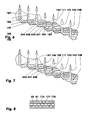
- FIGS. 4 and 5 for example, two further variants of the end face (35) of a light distributor (30) are shown.
- the surface elements (238) are e.g. 10% longer than the surface elements (38) shown in Figure 1.
- the free surface elements (239) and the surface elements (238) define an acute-angled wedge.
- FIG. 5 shows surface elements (338) which are embossed in the light distributor (30). Also these surface elements (338) For example, lie parallel to the light entry surface of the light distributor (30), not shown here.
- the free surface elements (339) each connect a surface element (338) with an oblique surface element (37) arranged above in the illustration of FIG.
- the long end faces (36, 56) of the light distributors (30, 50) each consist of, for example, 25 arranged surface elements (40-42, 60-62), cf. Figures 1 and 2.
- One half (40, 41, 60, 61) of these surface elements (40-42; 60-62) is e.g. staggered parallel to the sloping surface elements (37; 57) of the short end faces (35; 55).
- These surface elements (40, 41, 60, 61) are referred to below as step surface elements (40, 41, 60, 61).
- the other, likewise staggered surface elements (42, 62) are free-surface elements and connect the surface elements (40, 41, 60, 61) to one another.
- the free surface elements (42, 62) enclose an angle which is, for example, less than 135 degrees, each with a step surface element (40, 41, 60, 61) adjacent in a crown section (44;
- two adjacent peak sections (44, 64) have, for example, the same distance from each other.
- the step surface elements (40, 41; 60, 61) have two different sizes in the light distributors (30, 50) shown in FIGS. 1 and 2.
- the fourth, seventh, tenth, and thirteenth step surfaces (41, 61) are 50% larger than the remaining step surfaces (40, 60) as counted by the light entrance surface (31; Each parallel to the light entry surface (31; 51)
- an imaginary straight line in the longitudinal direction of the light distributor (30; 50) through an open-space element (39; 59) of the short end face (35) intersects a large step surface element (41; 61) of the long end face (36).
- FIGS. 6 and 7 show further embodiments of a long end face (36).
- the number and the angular position of the step surface elements (240, 241, 340, 341) are identical to the embodiment shown in FIGS. 1 and 2, for example.
- the distance of the apex paths (244, 245) projected onto the plane of the light entry surface (31) is not constant.
- the crests (244) bound the small step surface elements (240), the crests (245) lie on the large step surface elements (241).
- the large step surface elements (241) are 87% larger than the small step surface elements (240).
- the light distributor (30) shown in Figure 7 has step surfaces (340, 341) of different sizes.
- the large step surface elements (341) for example, 80% larger than the small step surface elements (340).
- All vertex sections (344) delimiting a large step surface element (341) have the same distance in a projection onto the plane of the light entrance side (31), for example, to both adjacent vertex sections (344) each delimiting a large step surface element (341).
- the single light distributor (30; 50) may comprise combinations of the described embodiments. For example, it can have a short end face (35, 55) according to FIG. 4 and a long end face (36, 56) according to FIG.
- end faces (35, 36, 55, 56) may have different configurations in sections.
- the two light distributors (30; 50) may also be interconnected, e.g. by means of a central web of constant strength.
- a single rotationally symmetrical light distributor can also be used.
- the axis of rotation in this case is, for example, the optical axis (22) of the light source (10).
- light (101 - 108) is generated by the light-emitting chip (11) in the light source (10).
- a part of the light (101 - 108) emitted by the light-emitting chip (11) in dashed lines in FIG. 1 strikes the boundary surface of the light deflecting body (13) formed by the converging lens (16).
- the angle enclosed by the incident light and a normal at the point of impact is less than the critical angle of total reflection. This critical angle is PMMA 42 degrees, for example.
- the incident light passes through the condenser lens, refracting it in the direction of the optical axis (22).
- the light emerging from the converging lens (16) lies parallel to the optical axis (22) of the lighting unit (5).
- the part of the light (101 - 108) emitted by the light-emitting chip (11) which does not pass through the converging lens (16) strikes the boundary of the light-deflecting body (13) formed by the lateral surface of the paraboloid stub (15). The angle of impact is greater as the critical angle of total reflection.
- This part of the light beam (101 - 108) is completely reflected in the direction of the light exit surface (19). It passes through the light exit surface (19) in the normal direction and is also parallel to the optical axis (22) of the light source (10).
- the light deflecting body (13) of the light source (10) parallelises or collimates the light (101 - 108) emitted by the light emitting chip (11). He thus acts for the light (101 - 108) as a collimator (113).
- the direction (9) of the parallelized light (101-108) emitted by the light source (10) is, for example, parallel to the optical axis (22) of the light source (10).
- the parallelized light (101-108) passes through the light entry surfaces (31, 51) into the light distributors (30, 50). In the light distributors (30, 50) it encounters the interfaces formed by the short end faces (35, 55). These two boundary surfaces form a light divider (135) for the light bundle (101-108).
- the light beam (101 - 108) impinges on the light divider (135) both in the sections in which the surface elements (38, 58), which are horizontal in FIG. 1, delimit the respective light distributor (30, 50) and on the gap (49) between the light distributors (30, 50) and in the sections in which the surface elements (37, 57) inclined in this figure form the body boundary.
- the light (104, 108) normally incident on the interface in the horizontal sections (38, 58) passes through these interfaces into the environment (1).
- the illuminated by the light source (10) areas of these interfaces are light transmission surfaces (138). These light passage surfaces (138) are at least approximately normal to the direction (9) of the parallel light (101 - 108).
- the gap (49) forms a light passage surface (138) through which a light beam (101) exits into the environment (1).
- All light transmission surfaces (138) have the same size in a projection opposite to the direction of the parallelized light (101 - 108) and the same distance to each two adjacent light transmission surfaces (138).
- These boundary surfaces form light reflection surfaces (137), at which the incident light (102, 103, 105 - 107), for example, completely in the longitudinal direction of the respective light divider (30, 50) is deflected. After reflection, the light bundles (102, 103, 105 - 107) are again parallel to one another.
- the light (101-108) emitted by the light source (10) is split at least in a manner similar to that in the light divider section (135) shown in these figures Figure 1 shown light divider (135).
- FIGS. 4 and 5 for example, only the central region is shown by the parallelized, tangent light bundles (103-108) for illustration purposes.
- the light (104, 108) passing through the light passage surfaces (138) becomes due to the recessed Open spaces (239) eg not reflected or broken.
- the light passage surfaces (138) in the exemplary embodiment according to FIG. 4 are only the regions of the boundary surfaces formed by the surface elements (238) which are illuminated by the light source (10).
- these interfaces are only partially illuminated.
- the illuminated regions are light-deflecting surfaces (142, 143, 145-147) of a light-deflecting region (140), at which the light bundles (102, 103, 105 - 107) are reflected in the direction of the light-emitting surface (32, 52).
- the light beam (102) impinges on the light deflection surface (142), the light bundle (103) on the light deflection surface (143) and the light bundle (105) on a light deflection surface (145).
- the latter is, for example, part of an interface formed by a large step surface element (41; 61).
- the light bundle (103) which lies, for example, in the illustration of FIG. 1 above the light bundle (102), touches the light deflecting surface (142) and strikes the light deflecting surface (143) located farthest from the light divider (135).
- the distance between the light deflection surfaces (142, 143, 145 - 147) is equal to one another.
- this distance also corresponds to the distance between the light passage surfaces 138 and the light deflection surfaces 142, 143, 145-147.
- the areas (138, 142, 143, 145-147) are the same size in the projection.
- the interfaces formed by the free surface elements (42, 62) do not influence the light (102, 103, 105 - 107), for example no reflection or refraction of the light bundles (102, 103, 105-107).
- the light bundles (101 - 108) which pass through the light divider (135) and deflect in the deflection region (140) and exit at the light exit side (32; 52) have the same distance and the same cross section from each other.
- the gaps (111) do not appear and are not visible to the viewer.
- the light (101-108) emerging from FIGS. 1 and 2 is proportionally divided in terms of area. When observing from a suitable distance, it gives the impression of a uniformly distributed luminance.
- the gap (111) is likewise bridged in the light deflection region (140), so that a uniform luminous density distribution results.
- the light deflection surface (143) is formed by a large step surface element (241), while the light deflection surfaces (142, 145 - 147) are formed by small step surface elements (240).
- all the light deflection surfaces (142, 143, 145-147) are parts of interfaces that are formed by large step surface elements (341).
- the light-deflecting surfaces (142, 143, 145-147) projecting center lines of the light-deflecting surfaces (142, 143, 145-147) opposite the direction of the light (101, 108) emerging from the light exit surfaces (32, 52) then have the same distance from one another, for example.
- large light distributors (30; 50) such as the Weakening of the light intensity can be compensated by the material absorption.
- the light deflection surfaces (142, 143, 145-147) and light passage surfaces (138) projected in this way can also vary in size.
- areas of different light intensity can be compensated.
- areas of high light intensity can illuminate small light deflection surfaces (142, 143, 145-147) and light transmission surfaces (138), while areas of low light intensity illuminate large areas (138, 142, 143, 145 - 147).
- the light divider (135) and the light diverting surfaces (142, 143, 145-147) may be parts of different bodies.
- the light reflection surfaces (137) of the light divider (135) around the light deflection surfaces (142, 143, 145-147) can be mirror surfaces of individual, optionally adjustable mirrors.
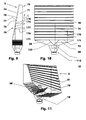
- Figures 9 and 10 show a front view and a side view of a lighting unit (5) with a surface light guide (70).
- a lighting unit (5) with a surface light guide (70).
- the surface light guide (70) shown in these figures 9 and 10 has the shape of a regular three-sided prism whose ground (71) and top surfaces are parallel and congruent right triangles. It is for example a transparent plastic body, for example of the same material as the Lichtumlenkraj (13) and / or the light distributor (30, 50).
- the underside (72) of the surface light guide (70) is e.g. a rectangular planar surface, which for example rests directly on the light exit surfaces (32, 52) of the light distributors (30, 50) and covers them.
- Perpendicular to this surface (72) is the e.g. designed as a flat surface front side (73) of the surface light guide (70).
- the height of the front side (73) of the surface light guide (70) shown shortened here is e.g. 80% larger than their length parallel to the light distributors (30, 50).
- the front side (73), which is the light exit surface (73) of the planar light guide (70), in this exemplary embodiment is twenty-five times the sum of the light exit surfaces (16, 19) of the light source (10).
- the light exit surface (73) can also be more than two hundred times as large as the sum of the light exit surfaces (16, 19).
- the back surface (74) of the surface light guide (70) has e.g. horizontal triangular notches (75).
- the length of the individual notches (75) is equal to the length of the surface light guide (70).
- These notches (75) are staggered at a constant distance from each other.
- the distance between the individual notches (75) is for example twice as large as the width of the individual notch (75), which is e.g. 0.5 mm to 1 mm.
- the two notched surfaces (76, 77) are in the illustration of Figures 9 and 10 plane surfaces.
- a normal to the lower notched area (76) terminates with an imaginary straight line normal to the lower face (72), e.g. an angle that is greater than or equal to the critical angle of total reflection for the material of the surface light guide (70) against air (1).
- a further, not shown, light source can be arranged on the back (78) of the surface light guide (70).
- the direction of the light emitted from this light source is then, for example, at least approximately normal to the light exit surface (73) of the surface light guide (70).
- the light (101 - 108) emitted by the light source (10) is divided, for example, in the light distributors (30, 50) as described in connection with FIGS. 1-7.
- the luminous flux is largely the same.
- the light bundles (101 - 108) enter through the lower side (72) in the surface light guide (70). In the surface light guide (70) they meet the boundary surfaces, which are formed by the notched surfaces (76). In FIGS. 9 and 10, for example, two possible light paths (171, 172) are shown. These light paths (171, 172), which are each partial light bundles of the light bundles (101 - 108), respectively illuminate part of the interfaces formed by the notched surfaces (76). The illuminated areas are light reflecting surfaces (176-178). The part of the luminous flux (101 - 108), which, for example, touches the light reflection surface (176), ie, passes right on the light reflection surface (176) in the representation of FIG. 9, strikes the light reflection surface (177) located farthest further.
- the partial luminous fluxes (171-172) impinging on these light reflection surfaces (176-178), for example, are completely deflected in the direction of the front side (73) and pass through this light exit surface (73) into the surroundings (1).
- the viewer sees from a distance of about two to three meters, the homogeneous luminous front (73) of the surface light guide (70) with a uniform luminance distribution.
- the light source arranged on the back side (78) of the surface light guide (70) is switched on, the light emitted by this light source penetrates the surface light guide (70) largely unhindered. The viewer can clearly see this additional light source. Depending on the luminance of the light source (10) and the additional light source, either the overall luminance is increased or only one light source is perceived during simultaneous operation of both light sources.
- the surface light guide (70) may be curved.
- the front side (73) of the surface light guide (70) can form the outer contour of a vehicle.
- the light distributors (30, 50) of such a lighting unit (5) may have a e.g. have a curved shape adapted to a vehicle outer contour.
- FIG. 11 shows a lighting unit (5) with a surface light guide (70) whose reflection surfaces (176-178) have optical structures (81).
- These optical structures (81) are, for example, a multiplicity of ellipsoidal cutouts (82) which are arched towards the surroundings (1).
- FIG. 8 shows a section of these optical structures (81), eg viewed from the underside (72) of a transparent planar light guide (70).
- the longitudinal axis of the individual imaginary ellipsoids in this case lies, for example, parallel to the underside (72) and parallel to the front side (73) of the surface light guide (70).
- the ellipsoid cutouts (82) arranged on the individual reflection surfaces (176-178) are, for example, offset relative to one another.
- the light beams (101-108) incident on the reflection surfaces (176-178) are reflected at the optical structures (81).
- the reflected light is distributed in space so that, for example, a solid angle range of +/- 20 degrees in the horizontal direction and +/- 10 degrees in the vertical direction is illuminated.
- FIG. 12 shows an arrangement of three lighting units (5). These are arranged side by side, e.g. the end faces of the surface light guides (70) adjoin one another. Hereby, for example, a large-scale light can be generated.
- a light source or it may be several light sources on the back (78) of the surface light guide (70) may be arranged.
- the light units (5) shown in FIGS. 1, 2, 9 - 12 can be made in one piece.
- the entire lighting unit (5) form an injection molded part, in which the light source (10) is formed or to which the light source (10) is integrally formed.
- the light source (10) besides being a light emitting diode, may be an incandescent lamp, a halogen lamp, etc., may also be clipped to or connected to the light distributors (30, 50) or otherwise connected thereto.
- the optical element (113) which parallelizes the light (101 - 108) emitted by the light source (10) may also be part a light distributor or the light distributor (30, 50).
- the light (101 - 108) incident on the light distributor (135) can for example also be parallelized or collimated by means of an optical lens, eg a parabolic reflector etc.
- the lighting unit (5) When the light source (10) is turned off, the lighting unit (5) appears clear and unstructured. When the light source (10) is turned on, from the position of the observer, a uniform luminous surface appears without interference.
- the lighting unit (5) is compact and can be used as part of a combined tail light in a motor vehicle, for example.
- this may include a tail light with arranged behind the brake light and / or turn signals.
Landscapes
- Engineering & Computer Science (AREA)
- General Engineering & Computer Science (AREA)
- Physics & Mathematics (AREA)
- Optics & Photonics (AREA)
- General Physics & Mathematics (AREA)
- Microelectronics & Electronic Packaging (AREA)
- Planar Illumination Modules (AREA)
- Non-Portable Lighting Devices Or Systems Thereof (AREA)
Priority Applications (1)
| Application Number | Priority Date | Filing Date | Title |
|---|---|---|---|
| SI200630874T SI1684002T1 (sl) | 2005-01-24 | 2006-01-12 | Svetilo s svetlobnim razdelilnikom |
Applications Claiming Priority (1)
| Application Number | Priority Date | Filing Date | Title |
|---|---|---|---|
| DE102005003367A DE102005003367B4 (de) | 2005-01-24 | 2005-01-24 | Leuchteinheit mit Lichtteiler |
Publications (3)
| Publication Number | Publication Date |
|---|---|
| EP1684002A2 true EP1684002A2 (fr) | 2006-07-26 |
| EP1684002A3 EP1684002A3 (fr) | 2008-09-17 |
| EP1684002B1 EP1684002B1 (fr) | 2010-11-03 |
Family
ID=35892460
Family Applications (1)
| Application Number | Title | Priority Date | Filing Date |
|---|---|---|---|
| EP06000553A Expired - Lifetime EP1684002B1 (fr) | 2005-01-24 | 2006-01-12 | Unité d' éclairage avec distributeur de lumière |
Country Status (5)
| Country | Link |
|---|---|
| US (1) | US7431481B2 (fr) |
| EP (1) | EP1684002B1 (fr) |
| KR (1) | KR20060085566A (fr) |
| DE (2) | DE102005003367B4 (fr) |
| SI (1) | SI1684002T1 (fr) |
Cited By (19)
| Publication number | Priority date | Publication date | Assignee | Title |
|---|---|---|---|---|
| DE102006008191A1 (de) * | 2006-02-22 | 2007-08-23 | Hella Kgaa Hueck & Co. | Leuchteneinheit für Fahrzeuge |
| EP2019251A3 (fr) * | 2007-07-25 | 2009-05-13 | Funai Electric Co., Ltd. | Témoin lumineux et poste de télévision |
| WO2010097185A1 (fr) * | 2009-02-25 | 2010-09-02 | Daimler Ag | Dispositif d'éclairage pour un véhicule automobile |
| EP2439132A3 (fr) * | 2010-10-11 | 2013-01-23 | Motogadget GmbH | Dispositif d'éclairage pour un véhicule |
| EP2784379A1 (fr) * | 2012-12-20 | 2014-10-01 | Automotive Lighting Reutlingen GmbH | Conducteur lumineux doté d'une surface de sortie de lumière en forme de bande |
| WO2015121243A1 (fr) * | 2014-02-11 | 2015-08-20 | Zumtobel Lighting Gmbh | Agencement de lentilles de forme allongée et constitué de plusieurs parties et lampe comportant un tel agencement |
| AT515790A4 (de) * | 2014-06-11 | 2015-12-15 | Zizala Lichtsysteme Gmbh | Beleuchtungsvorrichtung für ein Kraftfahrzeug sowie Fahrzeugscheinwerfer mit Beleuchtungsvorrichtung |
| AT515802B1 (de) * | 2014-06-11 | 2015-12-15 | Zizala Lichtsysteme Gmbh | Beleuchtungsvorrichtung für ein Fahrzeug sowie Fahrzeugscheinwerfer |
| EP3086025A1 (fr) * | 2015-04-20 | 2016-10-26 | Frowein EZH GmbH | Unite de rayonnement pour une lampe chirurgicale |
| CZ306729B6 (cs) * | 2012-10-03 | 2017-05-31 | Varroc Lighting Systems, s.r.o. | Světelný modul |
| DE102016114242A1 (de) * | 2016-08-02 | 2018-02-08 | Frowein Ezh Gmbh | Abstrahleinheit für eine Operationsleuchte |
| AT16042U1 (de) * | 2014-10-30 | 2018-12-15 | Zumtobel Lighting Gmbh | Optisches Element sowie Anordnung zur Lichtabgabe mit einem optischen Element |
| WO2021037587A1 (fr) * | 2019-08-28 | 2021-03-04 | Valeo Vision | Ensemble de guidage de lumière, feu de véhicule et véhicule |
| EP3875847A1 (fr) * | 2020-03-02 | 2021-09-08 | ZKW Group GmbH | Dispositif de feux de signalisation pour un projecteur de véhicule automobile |
| EP4015897A1 (fr) * | 2020-12-18 | 2022-06-22 | ZKW Group GmbH | Dispositif de feux de signalisation ou dispositif d'éclairage pour un phare de véhicule automobile |
| FR3124246A1 (fr) * | 2021-06-22 | 2022-12-23 | Psa Automobiles Sa | Dispositif d’éclairage à guide de lumière à face avant de sortie de photons |
| FR3126745A1 (fr) * | 2021-09-08 | 2023-03-10 | Psa Automobiles Sa | Dispositif d’éclairage à guide de lumière à face arrière réfléchissant des photons vers l’intégralité d’une face avant de sortie |
| WO2024023269A1 (fr) * | 2022-07-28 | 2024-02-01 | Valeo Vision | Unité de guidage de lumière, dispositif d'éclairage et véhicule à moteur |
| EP4538590A1 (fr) * | 2023-10-09 | 2025-04-16 | ZKW Group GmbH | Dispositif d'éclairage ou d'éclairage de signal pour un vehicule |
Families Citing this family (65)
| Publication number | Priority date | Publication date | Assignee | Title |
|---|---|---|---|---|
| DE102007013082A1 (de) * | 2007-03-14 | 2008-09-18 | Hella Kgaa Hueck & Co. | Signalleuchte |
| JP4968784B2 (ja) * | 2007-04-09 | 2012-07-04 | シチズン電子株式会社 | 光学部材の作製方法及び照明装置の作製方法 |
| CN101359122B (zh) * | 2007-08-03 | 2011-05-04 | 清华大学 | 背光模组 |
| US20090207610A1 (en) * | 2008-02-19 | 2009-08-20 | Edwin Mitchell Sayers | Combination rear lighting system |
| JP5070129B2 (ja) * | 2008-05-22 | 2012-11-07 | 株式会社小糸製作所 | 車両用照明灯具 |
| EP2297513A1 (fr) * | 2008-05-30 | 2011-03-23 | Koninklijke Philips Electronics N.V. | Dispositif d'éclairage comprenant un collimateur |
| DE102008061716A1 (de) * | 2008-12-12 | 2010-06-17 | Bayerische Motoren Werke Aktiengesellschaft | Fahrzeugleuchte und Leuchtensystem |
| JP5369359B2 (ja) * | 2009-04-13 | 2013-12-18 | スタンレー電気株式会社 | 灯具 |
| JP2011040279A (ja) * | 2009-08-11 | 2011-02-24 | Sony Corp | 面状照明装置 |
| JP5440857B2 (ja) * | 2010-03-05 | 2014-03-12 | スタンレー電気株式会社 | 車両用灯具ユニット、及び、車両用灯具 |
| JP5563416B2 (ja) * | 2010-09-22 | 2014-07-30 | スタンレー電気株式会社 | 電球互換型ledランプ |
| JP5657358B2 (ja) * | 2010-12-02 | 2015-01-21 | スタンレー電気株式会社 | 車両用灯具 |
| CN102691890A (zh) * | 2011-03-21 | 2012-09-26 | 欧司朗股份有限公司 | 全向照明装置 |
| US8696173B2 (en) * | 2011-06-08 | 2014-04-15 | GE Lighting Solutions, LLC | Low profile lamp using TIR lens |
| EP2543540A1 (fr) | 2011-07-07 | 2013-01-09 | Odelo GmbH | Conducteur lumineux, moyen d'éclairage et éclairage de véhicule automobile |
| EP2554897A1 (fr) | 2011-08-04 | 2013-02-06 | Odelo GmbH | Conducteur lumineux, moyen d'éclairage et éclairage de véhicule automobile |
| US9028120B2 (en) | 2011-08-08 | 2015-05-12 | Quarkstar Llc | Illumination devices including multiple light emitting elements |
| US9081125B2 (en) | 2011-08-08 | 2015-07-14 | Quarkstar Llc | Illumination devices including multiple light emitting elements |
| AT512056B1 (de) * | 2011-11-08 | 2013-05-15 | Zizala Lichtsysteme Gmbh | Lichtleitelement sowie lichteinheit |
| EP2800087B1 (fr) | 2011-12-27 | 2019-02-06 | Saturn Licensing LLC | Dispositif luminescent |
| US9746173B2 (en) | 2012-09-13 | 2017-08-29 | Quarkstar Llc | Illumination devices including enclosure panels with luminaire modules |
| CN104755832B (zh) | 2012-09-13 | 2018-12-21 | 夸克星有限责任公司 | 提供直接和间接照明的照明系统 |
| EP2909659A1 (fr) * | 2012-10-19 | 2015-08-26 | Koninklijke Philips N.V. | Dispositif d'éclairage destiné à un éclairage indirect et comportant des éléments prismatiques |
| WO2014074842A1 (fr) * | 2012-11-08 | 2014-05-15 | Fraen Corporation | Optique de mélange de couleur multi-del/multi-puce |
| CN102937269A (zh) * | 2012-11-15 | 2013-02-20 | 京东方科技集团股份有限公司 | 一种导光板、背光模组及显示装置 |
| WO2014117330A1 (fr) * | 2013-01-30 | 2014-08-07 | Nokia Corporation | Couvercle, dispositif électronique portable l'utilisant et son procédé de fabrication |
| WO2014124285A2 (fr) | 2013-02-08 | 2014-08-14 | Quarkstar Llc | Dispositif d'éclairage fournissant un éclairage direct et indirect |
| DE102013101344B4 (de) * | 2013-02-12 | 2024-11-07 | HELLA GmbH & Co. KGaA | Optisches System für eine Beleuchtungsvorrichtung für Fahrzeuge |
| US9714756B2 (en) | 2013-03-15 | 2017-07-25 | Morgan Solar Inc. | Illumination device |
| US9595627B2 (en) | 2013-03-15 | 2017-03-14 | John Paul Morgan | Photovoltaic panel |
| US9960303B2 (en) | 2013-03-15 | 2018-05-01 | Morgan Solar Inc. | Sunlight concentrating and harvesting device |
| MX344619B (es) | 2013-03-15 | 2017-01-03 | Morgan Solar Inc | Panel de luz, montaje optico con interfaz mejorada y panel de luz con tolerancias mejoradas de fabricacion. |
| US10208923B2 (en) * | 2013-03-15 | 2019-02-19 | Cree, Inc. | Optical components for luminaire |
| EP3270041B1 (fr) | 2013-04-19 | 2019-07-10 | Quarkstar LLC | Dispositifs d'éclairage ayant des éléments optiques réglables |
| DE102013210257A1 (de) * | 2013-06-03 | 2014-12-18 | Automotive Lighting Reutlingen Gmbh | Vorsatzoptik für eine Lichtquelle |
| CN105659027B (zh) | 2013-07-18 | 2018-03-13 | 夸克星有限责任公司 | 源光注入不平行于装置光轴的照明装置 |
| JP5968276B2 (ja) * | 2013-07-30 | 2016-08-10 | 株式会社東海理化電機製作所 | 車両用ミラー装置 |
| WO2015042174A1 (fr) | 2013-09-17 | 2015-03-26 | Quarkstar Llc | Dispositif d'éclairage à guide de lumière, doté d'un modificateur de divergence de lumière |
| JP5883109B2 (ja) * | 2014-11-26 | 2016-03-09 | スタンレー電気株式会社 | 車両用灯具 |
| DE102015214439A1 (de) * | 2015-07-30 | 2017-02-02 | Bayerische Motoren Werke Aktiengesellschaft | Leuchteinrichtung für ein Fahrzeug, insbesondere Fahrtrichtungsanzeiger für ein Zweirad |
| TWI622733B (zh) * | 2016-01-18 | 2018-05-01 | 元太科技工業股份有限公司 | 發光裝置及其導光板 |
| US11585515B2 (en) | 2016-01-28 | 2023-02-21 | Korrus, Inc. | Lighting controller for emulating progression of ambient sunlight |
| US10253948B1 (en) | 2017-03-27 | 2019-04-09 | EcoSense Lighting, Inc. | Lighting systems having multiple edge-lit lightguide panels |
| US12385623B2 (en) | 2016-01-28 | 2025-08-12 | Korrus, Inc. | Beam-shaping lighting systems |
| US11635188B2 (en) | 2017-03-27 | 2023-04-25 | Korrus, Inc. | Lighting systems generating visible-light emissions for dynamically emulating sky colors |
| US10119682B2 (en) * | 2016-07-05 | 2018-11-06 | Philips Lighting Holding B.V. | Luminaire having improved uniformity of output |
| JP6721453B2 (ja) | 2016-08-08 | 2020-07-15 | マクセル株式会社 | ヘッドアップディスプレイ装置およびその映像表示装置 |
| CN109237421A (zh) * | 2017-05-19 | 2019-01-18 | 市光法雷奥(佛山)汽车照明系统有限公司 | 用于机动车辆的发光装置 |
| DE102017112805A1 (de) * | 2017-06-09 | 2018-12-13 | Automotive Lighting Reutlingen Gmbh | Transparente Bauteilanordnung eines Leuchtenmoduls und Leuchtenmodul mit einer solchen transparenten Bauteilanordnung |
| CZ307412B6 (cs) * | 2017-06-13 | 2018-08-01 | Varroc Lighting Systems, s.r.o. | Světlovodivý optický systém |
| CZ310076B6 (cs) * | 2017-09-14 | 2024-07-24 | PO LIGHTING CZECH s.r.o. | Světlovodivý optický systém, zejména pro světelné zařízení vozidla |
| JP7017394B2 (ja) * | 2017-12-14 | 2022-02-08 | 株式会社小糸製作所 | ライトガイド装置 |
| CN110274206B (zh) * | 2018-03-14 | 2023-03-24 | 株式会社小糸制作所 | 车辆用灯具 |
| TWI844572B (zh) * | 2018-11-07 | 2024-06-11 | 荷蘭商露明控股公司 | 光導及相關之照明系統及成像系統 |
| CN111664420A (zh) * | 2019-03-07 | 2020-09-15 | 珠海雷士照明电气有限公司 | 灯具及其透镜 |
| CN211293468U (zh) * | 2019-05-14 | 2020-08-18 | 法雷奥照明湖北技术中心有限公司 | 光学结构、相应的车灯和车辆 |
| GB2585687B (en) | 2019-07-11 | 2021-08-18 | Dyson Technology Ltd | Vehicle lamps |
| DE102019211799B4 (de) * | 2019-08-06 | 2024-02-01 | Volkswagen Aktiengesellschaft | Vorrichtung zum Erzeugen einer Lichtverteilung für ein Fahrzeug |
| CN110630977B (zh) * | 2019-10-25 | 2024-08-23 | 马瑞利汽车零部件(芜湖)有限公司 | 一种实现均匀深邃的3d点亮效果的车灯光学系统 |
| CZ2020178A3 (cs) * | 2020-03-30 | 2021-06-02 | Varroc Lighting Systems, s.r.o. | Světlovodivá optická jednotka pro světelné zařízení motorových vozidel |
| EP4348328A1 (fr) | 2021-06-04 | 2024-04-10 | Signify Holding B.V. | Optique et système de mélange et de mise en forme de couleurs multiples |
| CN217382775U (zh) * | 2021-12-30 | 2022-09-06 | 市光法雷奥(佛山)汽车照明系统有限公司 | 准直器、照明装置和机动车辆 |
| DE102023105416A1 (de) | 2023-03-06 | 2024-09-12 | Marelli Automotive Lighting Reutlingen (Germany) GmbH | Lichtleiter und Beleuchtungseinrichtung mit einem Lichtleiter |
| DE102023131399A1 (de) | 2023-11-13 | 2025-05-15 | Miele & Cie. Kg | Haushaltsgerät |
| DE102024205342A1 (de) * | 2024-06-10 | 2025-12-11 | Continental Automotive Technologies GmbH | Lichtleiter für eine Anzeigevorrichtung |
Citations (1)
| Publication number | Priority date | Publication date | Assignee | Title |
|---|---|---|---|---|
| EP0780265B1 (fr) | 1995-12-21 | 2001-10-24 | Reitter & Schefenacker GmbH & Co. KG | Feu arrière pour véhicule |
Family Cites Families (11)
| Publication number | Priority date | Publication date | Assignee | Title |
|---|---|---|---|---|
| US4698730A (en) * | 1986-08-01 | 1987-10-06 | Stanley Electric Co., Ltd. | Light-emitting diode |
| US5890796A (en) * | 1997-01-16 | 1999-04-06 | Ford Global Technologies, Inc. | Laser illuminated lighting system utilizing a diffractive optical element |
| DE69803297T2 (de) * | 1997-08-12 | 2002-08-22 | Breault Res Organization Inc | Doppelreflektierende linse |
| US6036340A (en) * | 1998-03-03 | 2000-03-14 | Ford Global Technologies, Inc. | Dimpled manifold optical element for a vehicle lighting system |
| DE69911403T2 (de) * | 1998-06-11 | 2004-06-24 | Zumtobel Staff Gmbh | Licht verteilungssystem |
| DE10022420B4 (de) * | 2000-05-09 | 2007-04-26 | Automotive Lighting Reutlingen Gmbh | Fahrzeugleuchte |
| FR2846400B1 (fr) * | 2002-10-28 | 2005-10-07 | Valeo Vision | Feu de signalisation comportant un dispositif de recuperation et de repartition du flux lumineux vers un reflecteur annulaire |
| DE10309451A1 (de) * | 2003-03-05 | 2004-09-16 | Hella Kg Hueck & Co. | Fahrzeugleuchte |
| FR2853392B1 (fr) * | 2003-04-04 | 2006-06-16 | Sli Miniature Lighting Sa | Feu arriere, en particulier feu stop pour vehicule automobile |
| JP4300123B2 (ja) * | 2004-01-13 | 2009-07-22 | スタンレー電気株式会社 | 導光体を用いたled灯具 |
| US7195375B2 (en) * | 2004-01-28 | 2007-03-27 | Anvik Corporation | Compact, high-efficiency, energy-recycling illumination system |
-
2005
- 2005-01-24 DE DE102005003367A patent/DE102005003367B4/de not_active Expired - Fee Related
- 2005-12-13 KR KR1020050122598A patent/KR20060085566A/ko not_active Withdrawn
-
2006
- 2006-01-12 SI SI200630874T patent/SI1684002T1/sl unknown
- 2006-01-12 EP EP06000553A patent/EP1684002B1/fr not_active Expired - Lifetime
- 2006-01-12 DE DE502006008203T patent/DE502006008203D1/de not_active Expired - Lifetime
- 2006-01-23 US US11/337,354 patent/US7431481B2/en not_active Expired - Lifetime
Patent Citations (1)
| Publication number | Priority date | Publication date | Assignee | Title |
|---|---|---|---|---|
| EP0780265B1 (fr) | 1995-12-21 | 2001-10-24 | Reitter & Schefenacker GmbH & Co. KG | Feu arrière pour véhicule |
Cited By (31)
| Publication number | Priority date | Publication date | Assignee | Title |
|---|---|---|---|---|
| DE102006008191A1 (de) * | 2006-02-22 | 2007-08-23 | Hella Kgaa Hueck & Co. | Leuchteneinheit für Fahrzeuge |
| EP2019251A3 (fr) * | 2007-07-25 | 2009-05-13 | Funai Electric Co., Ltd. | Témoin lumineux et poste de télévision |
| US8049641B2 (en) | 2007-07-25 | 2011-11-01 | Funai Electric Co., Ltd. | Indicator unit and television set |
| WO2010097185A1 (fr) * | 2009-02-25 | 2010-09-02 | Daimler Ag | Dispositif d'éclairage pour un véhicule automobile |
| EP2439132A3 (fr) * | 2010-10-11 | 2013-01-23 | Motogadget GmbH | Dispositif d'éclairage pour un véhicule |
| CZ306729B6 (cs) * | 2012-10-03 | 2017-05-31 | Varroc Lighting Systems, s.r.o. | Světelný modul |
| US9528682B2 (en) | 2012-12-20 | 2016-12-27 | Automotive Lighting Reutlingen Gmbh | Light conductor with a ribbon-shaped light emitting area |
| EP2784379A1 (fr) * | 2012-12-20 | 2014-10-01 | Automotive Lighting Reutlingen GmbH | Conducteur lumineux doté d'une surface de sortie de lumière en forme de bande |
| WO2015121243A1 (fr) * | 2014-02-11 | 2015-08-20 | Zumtobel Lighting Gmbh | Agencement de lentilles de forme allongée et constitué de plusieurs parties et lampe comportant un tel agencement |
| US10113709B2 (en) | 2014-02-11 | 2018-10-30 | Zumtobel Lighting Gmbh | Elongate multipartite lens arrangement and luminaire comprising such a lens arrangement |
| AT15726U1 (de) * | 2014-02-11 | 2018-05-15 | Zumtobel Lighting Gmbh | Längliche mehrteilige Linsenanordnung sowie Leuchte mit einer solchen Linsenanordnung |
| CN105960562A (zh) * | 2014-02-11 | 2016-09-21 | 宗拓贝尔照明器材有限公司 | 长条形多件式透镜组以及具有这样的透镜组的灯 |
| EP3105499B1 (fr) | 2014-02-11 | 2017-11-22 | Zumtobel Lighting GmbH | Agencement de lentilles de forme allongée et constitué de plusieurs parties et lampe comportant un tel agencement |
| CN113513737A (zh) * | 2014-02-11 | 2021-10-19 | 宗拓贝尔照明器材有限公司 | 长条形多件式透镜组以及具有这样的透镜组的灯 |
| AT515790A4 (de) * | 2014-06-11 | 2015-12-15 | Zizala Lichtsysteme Gmbh | Beleuchtungsvorrichtung für ein Kraftfahrzeug sowie Fahrzeugscheinwerfer mit Beleuchtungsvorrichtung |
| AT515802B1 (de) * | 2014-06-11 | 2015-12-15 | Zizala Lichtsysteme Gmbh | Beleuchtungsvorrichtung für ein Fahrzeug sowie Fahrzeugscheinwerfer |
| AT515790B1 (de) * | 2014-06-11 | 2015-12-15 | Zizala Lichtsysteme Gmbh | Beleuchtungsvorrichtung für ein Kraftfahrzeug sowie Fahrzeugscheinwerfer mit Beleuchtungsvorrichtung |
| AT515802A4 (de) * | 2014-06-11 | 2015-12-15 | Zizala Lichtsysteme Gmbh | Beleuchtungsvorrichtung für ein Fahrzeug sowie Fahrzeugscheinwerfer |
| AT16042U1 (de) * | 2014-10-30 | 2018-12-15 | Zumtobel Lighting Gmbh | Optisches Element sowie Anordnung zur Lichtabgabe mit einem optischen Element |
| EP3086025A1 (fr) * | 2015-04-20 | 2016-10-26 | Frowein EZH GmbH | Unite de rayonnement pour une lampe chirurgicale |
| DE102016114242B4 (de) * | 2016-08-02 | 2020-10-08 | Frowein Ezh Gmbh | Abstrahleinheit für eine Operationsleuchte |
| DE102016114242A1 (de) * | 2016-08-02 | 2018-02-08 | Frowein Ezh Gmbh | Abstrahleinheit für eine Operationsleuchte |
| WO2021037587A1 (fr) * | 2019-08-28 | 2021-03-04 | Valeo Vision | Ensemble de guidage de lumière, feu de véhicule et véhicule |
| US11828432B2 (en) | 2019-08-28 | 2023-11-28 | Valeo Vision | Light-guiding assembly, vehicle lamp, and vehicle |
| EP3875847A1 (fr) * | 2020-03-02 | 2021-09-08 | ZKW Group GmbH | Dispositif de feux de signalisation pour un projecteur de véhicule automobile |
| EP4015897A1 (fr) * | 2020-12-18 | 2022-06-22 | ZKW Group GmbH | Dispositif de feux de signalisation ou dispositif d'éclairage pour un phare de véhicule automobile |
| FR3124246A1 (fr) * | 2021-06-22 | 2022-12-23 | Psa Automobiles Sa | Dispositif d’éclairage à guide de lumière à face avant de sortie de photons |
| FR3126745A1 (fr) * | 2021-09-08 | 2023-03-10 | Psa Automobiles Sa | Dispositif d’éclairage à guide de lumière à face arrière réfléchissant des photons vers l’intégralité d’une face avant de sortie |
| WO2024023269A1 (fr) * | 2022-07-28 | 2024-02-01 | Valeo Vision | Unité de guidage de lumière, dispositif d'éclairage et véhicule à moteur |
| EP4538590A1 (fr) * | 2023-10-09 | 2025-04-16 | ZKW Group GmbH | Dispositif d'éclairage ou d'éclairage de signal pour un vehicule |
| US12510221B2 (en) | 2023-10-09 | 2025-12-30 | Zkw Group Gmbh | Signal light or illumination device with multi-section light guiding body |
Also Published As
| Publication number | Publication date |
|---|---|
| SI1684002T1 (sl) | 2011-02-28 |
| DE102005003367A1 (de) | 2006-07-27 |
| KR20060085566A (ko) | 2006-07-27 |
| US7431481B2 (en) | 2008-10-07 |
| EP1684002A3 (fr) | 2008-09-17 |
| US20060164839A1 (en) | 2006-07-27 |
| EP1684002B1 (fr) | 2010-11-03 |
| DE502006008203D1 (de) | 2010-12-16 |
| DE102005003367B4 (de) | 2009-05-07 |
Similar Documents
| Publication | Publication Date | Title |
|---|---|---|
| EP1684002B1 (fr) | Unité d' éclairage avec distributeur de lumière | |
| EP1818599B1 (fr) | Feu de croisement, produisant une coupure à contraste importante | |
| DE102008005488B4 (de) | Scheinwerfer für Fahrzeuge | |
| EP2799761B1 (fr) | Module d'éclairage de phare de véhicule automobile | |
| EP2607774B1 (fr) | Dispositif d'éclairage d'un véhicule automobile avec une surface lumineuse longue et plane | |
| EP1818600B1 (fr) | Feu de croisement doté d'une production d'un point chaud | |
| DE102011085315A1 (de) | Scheinwerferprojektionsmodul für ein Kraftfahrzeug | |
| EP3473918B1 (fr) | Dispositif d'éclairage pour un phare de véhicule automobile | |
| DE20200571U1 (de) | Fahrzeugleuchte | |
| DE102012224079A1 (de) | Lichtleiter mit einer bandförmigen Lichtaustrittsfläche | |
| DE102012202508A1 (de) | Lichtleitervorrichtung für eine Kraftfahrzeugleuchte | |
| DE102011075510A1 (de) | Lichtmodul für einen Kraftfahrzeugscheinwerfer zur Erzeugung einer variablen Lichtverteilung und Kraftfahrzeugscheinwerfer mit einem solchen Lichtmodul | |
| DE102017115899B4 (de) | Kraftfahrzeugleuchte und Kraftfahrzeugscheinwerfer mit einer solchen Leuchte | |
| DE102017105838A1 (de) | Beleuchtungseinrichtung eines Kraftfahrzeugs mit einer Lichtleiteranordnung | |
| DE10140692A1 (de) | Beleuchtungseinrichtung | |
| EP2963334A2 (fr) | Système de conducteurs lumineux utilisé dans un dispositif d'éclairage d'un véhicule automobile et dispositif d'éclairage de véhicule automobile doté d'un tel système de conducteurs lumineux | |
| WO2020126350A1 (fr) | Dispositif d'éclairage pour un phare de véhicule automobile ainsi que phare de véhicule automobile | |
| EP1674789B1 (fr) | Unité de lampe avec une source de lumière, un guide de lumière et une zone permettant de réorienter la lumière | |
| DE102009035741A1 (de) | Kraftfahrzeugleuchte | |
| EP1464888A2 (fr) | Feu pour véhicule | |
| EP3461687B1 (fr) | Dispositif de guide de lumière d'un véhicule automobile et lampe de véhicule automobile muni d'un tel dispositif de guide de lumière | |
| DE102015204735A1 (de) | Lichtleiterelement einer Kraftfahrzeug-Beleuchtungseinrichtung und Kraftfahrzeug-Beleuchtungseinrichtung mit einem solchen Lichtleiterelement | |
| DE202014003075U1 (de) | Beleuchtungseinrichtung | |
| EP2835578A1 (fr) | Élément conducteur de lumière en forme de plaque en matériau transparent et module d'éclairage pour un dispositif d'éclairage de véhicule automobile doté d'un tel élément conducteur de lumière | |
| DE10355210A1 (de) | Leuchteinheit für Fahrzeuge |
Legal Events
| Date | Code | Title | Description |
|---|---|---|---|
| PUAI | Public reference made under article 153(3) epc to a published international application that has entered the european phase |
Free format text: ORIGINAL CODE: 0009012 |
|
| AK | Designated contracting states |
Kind code of ref document: A2 Designated state(s): AT BE BG CH CY CZ DE DK EE ES FI FR GB GR HU IE IS IT LI LT LU LV MC NL PL PT RO SE SI SK TR |
|
| AX | Request for extension of the european patent |
Extension state: AL BA HR MK YU |
|
| PUAL | Search report despatched |
Free format text: ORIGINAL CODE: 0009013 |
|
| AK | Designated contracting states |
Kind code of ref document: A3 Designated state(s): AT BE BG CH CY CZ DE DK EE ES FI FR GB GR HU IE IS IT LI LT LU LV MC NL PL PT RO SE SI SK TR |
|
| AX | Request for extension of the european patent |
Extension state: AL BA HR MK YU |
|
| 17P | Request for examination filed |
Effective date: 20090316 |
|
| AKX | Designation fees paid |
Designated state(s): DE FR IT SI |
|
| RAP1 | Party data changed (applicant data changed or rights of an application transferred) |
Owner name: ODELO GMBH |
|
| GRAP | Despatch of communication of intention to grant a patent |
Free format text: ORIGINAL CODE: EPIDOSNIGR1 |
|
| GRAS | Grant fee paid |
Free format text: ORIGINAL CODE: EPIDOSNIGR3 |
|
| GRAA | (expected) grant |
Free format text: ORIGINAL CODE: 0009210 |
|
| AK | Designated contracting states |
Kind code of ref document: B1 Designated state(s): DE FR IT SI |
|
| REF | Corresponds to: |
Ref document number: 502006008203 Country of ref document: DE Date of ref document: 20101216 Kind code of ref document: P |
|
| PLBE | No opposition filed within time limit |
Free format text: ORIGINAL CODE: 0009261 |
|
| STAA | Information on the status of an ep patent application or granted ep patent |
Free format text: STATUS: NO OPPOSITION FILED WITHIN TIME LIMIT |
|
| 26N | No opposition filed |
Effective date: 20110804 |
|
| REG | Reference to a national code |
Ref country code: DE Ref legal event code: R097 Ref document number: 502006008203 Country of ref document: DE Effective date: 20110804 |
|
| PGFP | Annual fee paid to national office [announced via postgrant information from national office to epo] |
Ref country code: FR Payment date: 20120206 Year of fee payment: 7 |
|
| PGFP | Annual fee paid to national office [announced via postgrant information from national office to epo] |
Ref country code: SI Payment date: 20130103 Year of fee payment: 8 |
|
| REG | Reference to a national code |
Ref country code: DE Ref legal event code: R082 Ref document number: 502006008203 Country of ref document: DE Representative=s name: RPK PATENTANWAELTE REINHARDT, POHLMANN UND KAU, DE |
|
| REG | Reference to a national code |
Ref country code: FR Ref legal event code: ST Effective date: 20130930 |
|
| PG25 | Lapsed in a contracting state [announced via postgrant information from national office to epo] |
Ref country code: FR Free format text: LAPSE BECAUSE OF NON-PAYMENT OF DUE FEES Effective date: 20130131 |
|
| REG | Reference to a national code |
Ref country code: SI Ref legal event code: KO00 Effective date: 20140910 |
|
| REG | Reference to a national code |
Ref country code: DE Ref legal event code: R082 Ref document number: 502006008203 Country of ref document: DE Representative=s name: RPK PATENTANWAELTE REINHARDT, POHLMANN UND KAU, DE |
|
| PG25 | Lapsed in a contracting state [announced via postgrant information from national office to epo] |
Ref country code: SI Free format text: LAPSE BECAUSE OF NON-PAYMENT OF DUE FEES Effective date: 20140113 |
|
| PGFP | Annual fee paid to national office [announced via postgrant information from national office to epo] |
Ref country code: IT Payment date: 20170124 Year of fee payment: 12 |
|
| REG | Reference to a national code |
Ref country code: DE Ref legal event code: R079 Ref document number: 502006008203 Country of ref document: DE Free format text: PREVIOUS MAIN CLASS: F21S0008100000 Ipc: F21S0043000000 |
|
| PG25 | Lapsed in a contracting state [announced via postgrant information from national office to epo] |
Ref country code: IT Free format text: LAPSE BECAUSE OF NON-PAYMENT OF DUE FEES Effective date: 20180112 |
|
| PGFP | Annual fee paid to national office [announced via postgrant information from national office to epo] |
Ref country code: DE Payment date: 20220620 Year of fee payment: 18 |
|
| REG | Reference to a national code |
Ref country code: DE Ref legal event code: R119 Ref document number: 502006008203 Country of ref document: DE |
|
| PG25 | Lapsed in a contracting state [announced via postgrant information from national office to epo] |
Ref country code: DE Free format text: LAPSE BECAUSE OF NON-PAYMENT OF DUE FEES Effective date: 20240801 |
|
| PG25 | Lapsed in a contracting state [announced via postgrant information from national office to epo] |
Ref country code: DE Free format text: LAPSE BECAUSE OF NON-PAYMENT OF DUE FEES Effective date: 20240801 |