EP1684055A1 - Débitmètre massique à effet Coriolis - Google Patents
Débitmètre massique à effet Coriolis Download PDFInfo
- Publication number
- EP1684055A1 EP1684055A1 EP05022876A EP05022876A EP1684055A1 EP 1684055 A1 EP1684055 A1 EP 1684055A1 EP 05022876 A EP05022876 A EP 05022876A EP 05022876 A EP05022876 A EP 05022876A EP 1684055 A1 EP1684055 A1 EP 1684055A1
- Authority
- EP
- European Patent Office
- Prior art keywords
- measuring tubes
- common plane
- mass flowmeter
- vibrations
- measuring
- Prior art date
- Legal status (The legal status is an assumption and is not a legal conclusion. Google has not performed a legal analysis and makes no representation as to the accuracy of the status listed.)
- Granted
Links
Images



Classifications
-
- G—PHYSICS
- G01—MEASURING; TESTING
- G01F—MEASURING VOLUME, VOLUME FLOW, MASS FLOW OR LIQUID LEVEL; METERING BY VOLUME
- G01F1/00—Measuring the volume flow or mass flow of fluid or fluent solid material wherein the fluid passes through a meter in a continuous flow
- G01F1/76—Devices for measuring mass flow of a fluid or a fluent solid material
- G01F1/78—Direct mass flowmeters
- G01F1/80—Direct mass flowmeters operating by measuring pressure, force, momentum, or frequency of a fluid flow to which a rotational movement has been imparted
- G01F1/84—Coriolis or gyroscopic mass flowmeters
- G01F1/8409—Coriolis or gyroscopic mass flowmeters constructional details
- G01F1/8413—Coriolis or gyroscopic mass flowmeters constructional details means for influencing the flowmeter's motional or vibrational behaviour, e.g., conduit support or fixing means, or conduit attachments
-
- G—PHYSICS
- G01—MEASURING; TESTING
- G01F—MEASURING VOLUME, VOLUME FLOW, MASS FLOW OR LIQUID LEVEL; METERING BY VOLUME
- G01F1/00—Measuring the volume flow or mass flow of fluid or fluent solid material wherein the fluid passes through a meter in a continuous flow
- G01F1/76—Devices for measuring mass flow of a fluid or a fluent solid material
- G01F1/78—Direct mass flowmeters
- G01F1/80—Direct mass flowmeters operating by measuring pressure, force, momentum, or frequency of a fluid flow to which a rotational movement has been imparted
- G01F1/84—Coriolis or gyroscopic mass flowmeters
- G01F1/845—Coriolis or gyroscopic mass flowmeters arrangements of measuring means, e.g., of measuring conduits
- G01F1/8468—Coriolis or gyroscopic mass flowmeters arrangements of measuring means, e.g., of measuring conduits vibrating measuring conduits
- G01F1/849—Coriolis or gyroscopic mass flowmeters arrangements of measuring means, e.g., of measuring conduits vibrating measuring conduits having straight measuring conduits
- G01F1/8495—Coriolis or gyroscopic mass flowmeters arrangements of measuring means, e.g., of measuring conduits vibrating measuring conduits having straight measuring conduits with multiple measuring conduits
Definitions
- the invention relates to a mass flow meter, which operates on the Coriolis principle, with two at least in a section in a common plane extending tubes and a connecting means by means of which the two measuring tubes in the portion in which they extend in the common plane, connected to each other are.
- the present invention thus relates to such Coriolis mass flowmeters, which have at least two measuring tubes, which extend in the non-oscillating state at least in sections in a common plane, namely namely parallel to each other.
- Essential in such Coriolis mass flowmeters with two or more measuring tubes is the provision of at least one, optionally also two connecting devices, as described above. These connecting devices determine the effective length of the measuring range, since they fix the measuring tubes and thus each define a vibration node in the vibrational excitation of the measuring tubes.
- Such connecting devices are therefore also referred to as nodal plates.
- the inlet side and outlet side portions of the measuring tubes in front of and behind the nodal plates make the respective connection to the piping in which the Coriolis mass flowmeter is installed.
- These inlet and outlet side portions of the measuring tubes also contribute to the vibration isolation of the Coriolis mass flowmeter from the piping system.
- the connecting devices In addition to the determination of the effective measuring range of the Coriolis mass flowmeter, the connecting devices also serve to frequency-separate the excitation vibrations of the measuring tubes, which take place within the common plane of the measuring tubes, from orthogonal oscillations. The greater the frequency separation between these two oscillations, the less these two oscillations influence each other, However, there is still room for improvement in Coriolis mass flowmeters known from practice with two or more measuring tubes, since the influencing of the excitation oscillation by orthogonal oscillations of the measuring tubes and thus ultimately also the disturbance the measuring signal is still too large.
- the connecting device is designed and arranged so that their bending stiffness for bends in the common plane of the measuring tubes is greater than their torsional stiffness for torsional vibrations about the line connecting the between two measuring tubes.
- the bending stiffness of the connecting device for bends in the common plane of the measuring tubes in which also the excitation vibrations of the measuring tubes are generally greater than the torsional stiffness of the connecting device for torsional vibrations about such an axis that the connection points of the connecting device with connects the two measuring tubes together.
- connection means may be designed in a variety of ways to achieve that their bending stiffness for bends in the common plane of the measuring tubes is greater than their torsional stiffness for torsional vibrations about the connecting line between the two measuring tubes.
- the connecting device has two mutually opposite, in each case attached to two measuring tubes stiffening plates. These stiffening plates can be curved in principle, but according to a preferred embodiment of the invention, they are flat.
- stiffening plates can otherwise be directly or / and indirectly attached to the measuring tubes or with each other. According to a preferred embodiment of the invention, it is provided that the two stiffening plates are interconnected by means of a connecting plate. This may also be curved, but preferably it is also flat.
- the stiffening plates can be oriented differently from one another. According to a preferred embodiment of the invention, however, it is provided that the stiffening plates are aligned parallel to one another and preferably parallel to the common plane of the measuring tubes.
- the connecting device such that the stiffening plates and the connecting plate have the same thicknesses.
- the connection means z. B. simply from a common plate, namely by bending their side areas.
- the thickness of the connecting plate is greater than the thicknesses of the stiffening plates.
- the torsional rigidity for torsional vibrations around the connecting line between the two measuring tubes is reduced much more than the flexural rigidity for bends in the common plane of the measuring tubes.
- a connecting device with thinner stiffening plates opposes the excitation vibrations in the common plane of the measuring tubes to a significantly higher bending resistance than vibrations perpendicular thereto, which lead to torsional vibrations of the connecting device.
- the stiffening plates as already indicated above, be attached directly or indirectly to the measuring tubes, namely z. B. via the connection plate.
- the connecting plate for each measuring tube has a bore through which the respective measuring tube is passed. It is provided according to a preferred embodiment of the invention that the inner diameter of the bore substantially corresponds to the outer diameter of the measuring tubes and the measuring tubes are mounted in the bores.
- connecting means a variety of materials in question, such as various metals and plastic materials.
- connecting device for the attachment of the connecting device to the measuring tubes a variety of ways, such as welding, soldering, gluing, etc., in particular depending on the materials used.
- the connecting means 2 have in cross section in each case substantially a U-profile, wherein two stiffening plates 3 are connected to each other by means of a connecting plate 4, that the stiffening plates 3 are aligned parallel to each other and each perpendicular to the connecting plate 4.
- the thickness of the stiffening plates 3 is less than the Dikke the connecting plate 4, whereby the effect already mentioned above is achieved, that the bending resistance of the connecting means 2 for torsional vibrations is significantly lower than for bending vibrations in the common plane of the measuring tubes. 1
- the connecting plate 4 two holes 5 are provided, whose inner diameter corresponds substantially to the outer diameter of the measuring tubes 1. In this way, the connecting means 2 can be pushed onto the measuring tubes 1 and then connected to them.
- the connecting means 2 are made of stainless steel, so that they can be welded to the measuring tubes 1 made of titanium.
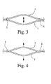
- FIGS. 3 and 4 how the connecting devices 2 act at different vibrations.
- Fig. 3 the two, connected to two connecting means 2 measuring tubes 1 are shown in a plan view, namely at the maximum deflection of an excitation oscillation, which takes place in the common plane of the measuring tubes 1.
- the connecting means 2 are claimed by the oscillating measuring tubes 1 so that it comes to bending vibrations of the connecting means 2 in the common plane of the measuring tubes 1.
- the stiffening plates 3 must also perform such bending vibrations in a corresponding plane. Such vibrations are opposed by the required upsetting of the stiffening plates 3 on the one hand and stretching on the opposite side, a very high bending resistance.
- the connecting means 2 can be relatively perpendicular to the vibrational excitation oscillations of vibrations of the measuring tubes 1 to torsional vibrations along the connecting line between the two measuring tubes 1 excite, as shown in Fig. 4. This frequency-wise good separation of these two types of vibration is achieved, which ultimately only a small influence the measurement signal is achieved by taking place perpendicular to the excitation vibrations oscillations of the measuring tubes.
- Fig. 5 is now with the relevant details and omitting sections of the measuring tubes 1 in the region of the connecting means 2 to better visualize the attachment of the measuring tubes 1 to the connecting device 2, a Coriolis mass flow meter according to a second preferred embodiment of the invention.
- the measuring tubes 1 are attached to the connecting device 2 not only in the holes 5, but also on the inner surfaces of the stiffening plates 3.
- welds 6 with the measuring tubes 1.
- Such an attachment is particularly advantageous in order to achieve a good frequency separation with longer measuring tubes 1, in particular if they have a small diameter.
- it is achieved namely, that the bending resistance, which the connecting device 2 opposite bending vibrations in the common plane of the measuring tubes 1, again significantly increased, while the torsional stiffness is hardly affected.
- a Coriolis mass flowmeter according to a third preferred embodiment of the invention can be seen.
- the connecting device 2 only consists of two stiffening plates 3, without these being connected to each other by means of a connecting plate 4.
- the stiffening plates 3, similar to the Coriolis mass flow meter according to the second preferred embodiment of the invention shown in FIG. 5, are welded to the measuring tubes 1 at their inner surfaces, as can be seen from the welds 6 shown in FIG.
- This construction is advantageous in that it is very inexpensive to produce and also easy to install.
- the principle of operation corresponds essentially to that of the apparent from Fig. 5 Coriolis mass flowmeter according to the second preferred embodiment of the invention, wherein only the action of the connecting plate 4 has been omitted, which, however, compared to the effect of the reinforcing plates 3 is substantially lower.
- connection means 2 for a Coriolis mass flowmeter according to a fourth preferred embodiment of the invention can be seen.
- This connecting device 2 shown there in section also has two stiffening plates 3 and a connecting plate 4 connecting them, wherein the connecting plate 4 is provided with holes 5 through which the measuring tubes 1 can be passed, so that the connecting device 2 are connected to the measuring tubes 1 can.
- the stiffening plates 3 are not arranged parallel to one another. Nevertheless, the effect is also achieved here that bends of the connecting device 2 in the common plane of the measuring tubes 1, a greater bending resistance is opposed, as torsional vibrations to the connecting line between the two measuring tubes. 1
Landscapes
- Physics & Mathematics (AREA)
- Fluid Mechanics (AREA)
- General Physics & Mathematics (AREA)
- Measuring Volume Flow (AREA)
- Harvester Elements (AREA)
- Processing Of Solid Wastes (AREA)
Applications Claiming Priority (1)
| Application Number | Priority Date | Filing Date | Title |
|---|---|---|---|
| DE102005003161A DE102005003161B4 (de) | 2005-01-21 | 2005-01-21 | Massendurchflußmeßgerät |
Publications (2)
| Publication Number | Publication Date |
|---|---|
| EP1684055A1 true EP1684055A1 (fr) | 2006-07-26 |
| EP1684055B1 EP1684055B1 (fr) | 2011-04-13 |
Family
ID=36218355
Family Applications (1)
| Application Number | Title | Priority Date | Filing Date |
|---|---|---|---|
| EP05022876A Expired - Lifetime EP1684055B1 (fr) | 2005-01-21 | 2005-10-20 | Débitmètre massique à effet Coriolis |
Country Status (6)
| Country | Link |
|---|---|
| US (1) | US7275449B2 (fr) |
| EP (1) | EP1684055B1 (fr) |
| JP (1) | JP4695988B2 (fr) |
| AT (1) | ATE505714T1 (fr) |
| DE (2) | DE102005003161B4 (fr) |
| DK (1) | DK1684055T3 (fr) |
Cited By (2)
| Publication number | Priority date | Publication date | Assignee | Title |
|---|---|---|---|---|
| WO2008059015A1 (fr) * | 2006-11-15 | 2008-05-22 | Siemens Aktiengesellschaft | Dispositif de mesure de débit massique |
| WO2014109747A1 (fr) * | 2013-01-10 | 2014-07-17 | Micro Motion, Inc. | Procédé et appareil pour dispositif de mesure de vibration |
Families Citing this family (11)
| Publication number | Priority date | Publication date | Assignee | Title |
|---|---|---|---|---|
| DE102006034274B4 (de) * | 2006-07-21 | 2012-06-28 | Krohne Ag | Massendurchflußmeßgerät |
| US7784359B2 (en) * | 2008-04-17 | 2010-08-31 | Rosemount Aerospace Inc. | Coriolis effect mass flow meter and gyroscope |
| DE102008035877A1 (de) * | 2008-08-01 | 2010-02-04 | Endress + Hauser Flowtec Ag | Meßwandler vom Vibrationstyp |
| WO2010059157A1 (fr) * | 2008-11-19 | 2010-05-27 | Micro Motion, Inc. | Débitmètre à effet coriolis avec séparation de mode améliorée |
| RU2464534C1 (ru) * | 2008-11-19 | 2012-10-20 | Майкро Моушн, Инк. | Расходомер (варианты) и способ увеличения разделительного интервала между двумя или более колебательными частотами вибрационного расходомера |
| DE102012109729A1 (de) | 2012-10-12 | 2014-05-15 | Endress + Hauser Flowtec Ag | Meßsystem zum Ermitteln eines Volumendruchflusses und/oder einer Volumendurchflußrate eines in einer Rohrleitung strömenden Mediums |
| EP2906915B1 (fr) | 2012-10-11 | 2022-04-20 | Endress+Hauser Flowtec AG | Système de mesure pour déterminer un débit volumique et/ou un pourcentage de débit volumique d'un fluide s'écoulant dans une tuyauterie |
| CN105358944B (zh) | 2013-04-18 | 2019-05-14 | 高准公司 | 自对准的撑杆 |
| JP7047071B2 (ja) * | 2017-08-29 | 2022-04-04 | マイクロ モーション インコーポレイテッド | 一体型ブレースバー |
| DE102018005197B3 (de) * | 2018-06-29 | 2019-11-14 | Rota Yokogawa Gmbh & Co. Kg | Coriolis-Massendurchfluss- und Dichtemessgerät mit verringerter Druckabhängigkeit |
| DE102019129744A1 (de) | 2019-11-05 | 2021-05-06 | Krohne Ag | Coriolis-Massendurchflussmessgerät und Knotenelement |
Citations (2)
| Publication number | Priority date | Publication date | Assignee | Title |
|---|---|---|---|---|
| US5602345A (en) * | 1994-05-26 | 1997-02-11 | Endress + Hauser Flowtec Ag | Double straight tube coriolis type mass flow sensor |
| EP1279935A2 (fr) * | 2001-07-23 | 2003-01-29 | FMC Technologies, Inc. | Procédé de découplage des modes de vibrations externes d'un débitmètre massique de type Coriolis |
Family Cites Families (13)
| Publication number | Priority date | Publication date | Assignee | Title |
|---|---|---|---|---|
| US4823614A (en) * | 1986-04-28 | 1989-04-25 | Dahlin Erik B | Coriolis-type mass flowmeter |
| US4781069A (en) * | 1986-06-05 | 1988-11-01 | Exac Corporation | Mode selection apparatus for multiple tube coriolis type mass flow meters |
| MX171455B (es) * | 1989-06-09 | 1993-10-27 | Micro Motion Inc | Medidor mejorado de flujo de masa para materiales fluidos en donde la velocidad del flujo de masa se determina en base al efecto de coriolis |
| JPH0499919A (ja) * | 1990-08-20 | 1992-03-31 | Tokico Ltd | 質量流量計 |
| US5226330A (en) * | 1991-10-31 | 1993-07-13 | Lew Hyok S | High sensitivity mass flowmeter |
| DE59201347D1 (de) * | 1992-11-06 | 1995-03-16 | Flowtec Ag | Coriolis-Massendurchflussmesser. |
| US5370002A (en) * | 1993-07-23 | 1994-12-06 | Micro Motion, Inc. | Apparatus and method for reducing stress in the brace bar of a Coriolis effect mass flow meter |
| JPH08271311A (ja) * | 1995-03-31 | 1996-10-18 | Tokico Ltd | 振動式測定装置 |
| JP2000046615A (ja) * | 1998-07-30 | 2000-02-18 | Yokogawa Electric Corp | コリオリ質量流量計 |
| US6308580B1 (en) | 1999-03-19 | 2001-10-30 | Micro Motion, Inc. | Coriolis flowmeter having a reduced flag dimension |
| JP2002340648A (ja) * | 2001-05-16 | 2002-11-27 | Oval Corp | コリオリ式質量流量計における振動管と支持板又は部材のロー付け固着構造 |
| EP1296119A1 (fr) * | 2001-09-21 | 2003-03-26 | Endress + Hauser Flowtec AG | Capteur de mesure du type vibrant |
| US6920798B2 (en) | 2001-09-21 | 2005-07-26 | Endress + Hauser Flowtec Ag | Vibratory transducer |
-
2005
- 2005-01-21 DE DE102005003161A patent/DE102005003161B4/de not_active Expired - Lifetime
- 2005-10-20 DK DK05022876.6T patent/DK1684055T3/da active
- 2005-10-20 AT AT05022876T patent/ATE505714T1/de active
- 2005-10-20 EP EP05022876A patent/EP1684055B1/fr not_active Expired - Lifetime
- 2005-10-20 DE DE502005011238T patent/DE502005011238D1/de not_active Expired - Lifetime
- 2005-12-12 US US11/299,612 patent/US7275449B2/en not_active Expired - Lifetime
-
2006
- 2006-01-18 JP JP2006009457A patent/JP4695988B2/ja not_active Expired - Fee Related
Patent Citations (2)
| Publication number | Priority date | Publication date | Assignee | Title |
|---|---|---|---|---|
| US5602345A (en) * | 1994-05-26 | 1997-02-11 | Endress + Hauser Flowtec Ag | Double straight tube coriolis type mass flow sensor |
| EP1279935A2 (fr) * | 2001-07-23 | 2003-01-29 | FMC Technologies, Inc. | Procédé de découplage des modes de vibrations externes d'un débitmètre massique de type Coriolis |
Cited By (6)
| Publication number | Priority date | Publication date | Assignee | Title |
|---|---|---|---|---|
| WO2008059015A1 (fr) * | 2006-11-15 | 2008-05-22 | Siemens Aktiengesellschaft | Dispositif de mesure de débit massique |
| WO2014109747A1 (fr) * | 2013-01-10 | 2014-07-17 | Micro Motion, Inc. | Procédé et appareil pour dispositif de mesure de vibration |
| CN105026898A (zh) * | 2013-01-10 | 2015-11-04 | 高准公司 | 用于振动仪的方法和装置 |
| RU2608340C1 (ru) * | 2013-01-10 | 2017-01-17 | Майкро Моушн, Инк. | Способ и устройство для вибрационного измерителя |
| US9696194B2 (en) | 2013-01-10 | 2017-07-04 | Micro Motion, Inc. | Method and apparatus for a vibratory meter |
| CN105026898B (zh) * | 2013-01-10 | 2018-02-06 | 高准公司 | 用于振动仪的方法和装置 |
Also Published As
| Publication number | Publication date |
|---|---|
| DE102005003161B4 (de) | 2007-03-01 |
| US7275449B2 (en) | 2007-10-02 |
| EP1684055B1 (fr) | 2011-04-13 |
| US20060162468A1 (en) | 2006-07-27 |
| JP4695988B2 (ja) | 2011-06-08 |
| DE102005003161A1 (de) | 2006-07-27 |
| DK1684055T3 (da) | 2011-07-25 |
| ATE505714T1 (de) | 2011-04-15 |
| DE502005011238D1 (de) | 2011-05-26 |
| JP2006201170A (ja) | 2006-08-03 |
Similar Documents
| Publication | Publication Date | Title |
|---|---|---|
| EP1798532B1 (fr) | Débitmètre massique de Coriolis | |
| EP1881303B1 (fr) | Débitmètre à effet Coriolis | |
| EP1528374B1 (fr) | Débitmètre massique de Coriolis | |
| EP1684055B1 (fr) | Débitmètre massique à effet Coriolis | |
| EP4302066B1 (fr) | Dispositif de mesure modulaire pour la détermination de la densité d'un milieu de mesure | |
| DE102011010178B4 (de) | Coriolis-Massedurchflussmessgerät | |
| DE19621365C2 (de) | Massendurchflußmeßgerät | |
| DE102008049891B4 (de) | Strömungsrichter für ein Durchflussmessgerät, insbesondere ein Ultraschallmessgerät | |
| EP2625492B1 (fr) | Débitmètre massique à effet coriolis | |
| EP2600122B1 (fr) | Débitmètre massique du type Coriolis | |
| EP0547455A1 (fr) | Débitmètre de masse | |
| DE102012016490A1 (de) | Coriolis-Massendurchflussmessgerät | |
| WO2008059015A1 (fr) | Dispositif de mesure de débit massique | |
| DE68907047T2 (de) | Massen-Strömungssensor. | |
| WO2018114197A1 (fr) | Capteur de mesure de type à oscillations permettant de mesurer la masse volumique et/ou le débit massique d'un milieu | |
| DE102015003365A1 (de) | Coriolis-Massendurchflussmessgerät | |
| DE102018001778A1 (de) | Massendurchfluss- und Dichtemesser nach dem Coriolis-Prinzip mit geringer Druckabhängigkeit und Verfahren zur Herstellung | |
| EP3819601B1 (fr) | Appareil de mesure de débit massique à effet coriolis et plaque de noeud | |
| DE4016907C2 (fr) | ||
| EP1528373A2 (fr) | Pièce de montage et débitmètre massique à effet coriolis avec cette pièce de montage | |
| DE102021118263A1 (de) | Anschlusseinheit, Schwingungsrohrmodul und modulare Messvorrichtung zum Ermitteln einer Dichte eines Messmediums | |
| WO2025045649A1 (fr) | Enregistreur de mesure vibronique pour mesure du débit massique d'un milieu fluide | |
| EP1421349B1 (fr) | Capteur de débit de fluide du type vibrant | |
| EP2559977B1 (fr) | Débitmètre massique Coriolis | |
| EP3559607B1 (fr) | Système de mesure du type vibrant pour mesurer la densité et/ou le débit d'un milieu en écoulement |
Legal Events
| Date | Code | Title | Description |
|---|---|---|---|
| PUAI | Public reference made under article 153(3) epc to a published international application that has entered the european phase |
Free format text: ORIGINAL CODE: 0009012 |
|
| AK | Designated contracting states |
Kind code of ref document: A1 Designated state(s): AT BE BG CH CY CZ DE DK EE ES FI FR GB GR HU IE IS IT LI LT LU LV MC NL PL PT RO SE SI SK TR |
|
| AX | Request for extension of the european patent |
Extension state: AL BA HR MK YU |
|
| 17P | Request for examination filed |
Effective date: 20061017 |
|
| 17Q | First examination report despatched |
Effective date: 20061115 |
|
| AKX | Designation fees paid |
Designated state(s): AT BE BG CH CY CZ DE DK EE ES FI FR GB GR HU IE IS IT LI LT LU LV MC NL PL PT RO SE SI SK TR |
|
| GRAP | Despatch of communication of intention to grant a patent |
Free format text: ORIGINAL CODE: EPIDOSNIGR1 |
|
| GRAS | Grant fee paid |
Free format text: ORIGINAL CODE: EPIDOSNIGR3 |
|
| GRAA | (expected) grant |
Free format text: ORIGINAL CODE: 0009210 |
|
| AK | Designated contracting states |
Kind code of ref document: B1 Designated state(s): AT BE BG CH CY CZ DE DK EE ES FI FR GB GR HU IE IS IT LI LT LU LV MC NL PL PT RO SE SI SK TR |
|
| REG | Reference to a national code |
Ref country code: GB Ref legal event code: FG4D Free format text: NOT ENGLISH |
|
| REG | Reference to a national code |
Ref country code: CH Ref legal event code: EP |
|
| REG | Reference to a national code |
Ref country code: IE Ref legal event code: FG4D Free format text: LANGUAGE OF EP DOCUMENT: GERMAN |
|
| REF | Corresponds to: |
Ref document number: 502005011238 Country of ref document: DE Date of ref document: 20110526 Kind code of ref document: P |
|
| REG | Reference to a national code |
Ref country code: DE Ref legal event code: R096 Ref document number: 502005011238 Country of ref document: DE Effective date: 20110526 |
|
| REG | Reference to a national code |
Ref country code: DK Ref legal event code: T3 |
|
| REG | Reference to a national code |
Ref country code: NL Ref legal event code: VDEP Effective date: 20110413 |
|
| LTIE | Lt: invalidation of european patent or patent extension |
Effective date: 20110413 |
|
| PG25 | Lapsed in a contracting state [announced via postgrant information from national office to epo] |
Ref country code: PT Free format text: LAPSE BECAUSE OF FAILURE TO SUBMIT A TRANSLATION OF THE DESCRIPTION OR TO PAY THE FEE WITHIN THE PRESCRIBED TIME-LIMIT Effective date: 20110816 Ref country code: SE Free format text: LAPSE BECAUSE OF FAILURE TO SUBMIT A TRANSLATION OF THE DESCRIPTION OR TO PAY THE FEE WITHIN THE PRESCRIBED TIME-LIMIT Effective date: 20110413 Ref country code: LT Free format text: LAPSE BECAUSE OF FAILURE TO SUBMIT A TRANSLATION OF THE DESCRIPTION OR TO PAY THE FEE WITHIN THE PRESCRIBED TIME-LIMIT Effective date: 20110413 |
|
| REG | Reference to a national code |
Ref country code: IE Ref legal event code: FD4D |
|
| PG25 | Lapsed in a contracting state [announced via postgrant information from national office to epo] |
Ref country code: LV Free format text: LAPSE BECAUSE OF FAILURE TO SUBMIT A TRANSLATION OF THE DESCRIPTION OR TO PAY THE FEE WITHIN THE PRESCRIBED TIME-LIMIT Effective date: 20110413 Ref country code: GR Free format text: LAPSE BECAUSE OF FAILURE TO SUBMIT A TRANSLATION OF THE DESCRIPTION OR TO PAY THE FEE WITHIN THE PRESCRIBED TIME-LIMIT Effective date: 20110714 Ref country code: SI Free format text: LAPSE BECAUSE OF FAILURE TO SUBMIT A TRANSLATION OF THE DESCRIPTION OR TO PAY THE FEE WITHIN THE PRESCRIBED TIME-LIMIT Effective date: 20110413 Ref country code: CY Free format text: LAPSE BECAUSE OF FAILURE TO SUBMIT A TRANSLATION OF THE DESCRIPTION OR TO PAY THE FEE WITHIN THE PRESCRIBED TIME-LIMIT Effective date: 20110413 Ref country code: IS Free format text: LAPSE BECAUSE OF FAILURE TO SUBMIT A TRANSLATION OF THE DESCRIPTION OR TO PAY THE FEE WITHIN THE PRESCRIBED TIME-LIMIT Effective date: 20110813 Ref country code: ES Free format text: LAPSE BECAUSE OF FAILURE TO SUBMIT A TRANSLATION OF THE DESCRIPTION OR TO PAY THE FEE WITHIN THE PRESCRIBED TIME-LIMIT Effective date: 20110724 Ref country code: FI Free format text: LAPSE BECAUSE OF FAILURE TO SUBMIT A TRANSLATION OF THE DESCRIPTION OR TO PAY THE FEE WITHIN THE PRESCRIBED TIME-LIMIT Effective date: 20110413 |
|
| PG25 | Lapsed in a contracting state [announced via postgrant information from national office to epo] |
Ref country code: NL Free format text: LAPSE BECAUSE OF FAILURE TO SUBMIT A TRANSLATION OF THE DESCRIPTION OR TO PAY THE FEE WITHIN THE PRESCRIBED TIME-LIMIT Effective date: 20110413 |
|
| PG25 | Lapsed in a contracting state [announced via postgrant information from national office to epo] |
Ref country code: IE Free format text: LAPSE BECAUSE OF FAILURE TO SUBMIT A TRANSLATION OF THE DESCRIPTION OR TO PAY THE FEE WITHIN THE PRESCRIBED TIME-LIMIT Effective date: 20110413 Ref country code: CZ Free format text: LAPSE BECAUSE OF FAILURE TO SUBMIT A TRANSLATION OF THE DESCRIPTION OR TO PAY THE FEE WITHIN THE PRESCRIBED TIME-LIMIT Effective date: 20110413 Ref country code: EE Free format text: LAPSE BECAUSE OF FAILURE TO SUBMIT A TRANSLATION OF THE DESCRIPTION OR TO PAY THE FEE WITHIN THE PRESCRIBED TIME-LIMIT Effective date: 20110413 |
|
| PLBE | No opposition filed within time limit |
Free format text: ORIGINAL CODE: 0009261 |
|
| STAA | Information on the status of an ep patent application or granted ep patent |
Free format text: STATUS: NO OPPOSITION FILED WITHIN TIME LIMIT |
|
| PG25 | Lapsed in a contracting state [announced via postgrant information from national office to epo] |
Ref country code: RO Free format text: LAPSE BECAUSE OF FAILURE TO SUBMIT A TRANSLATION OF THE DESCRIPTION OR TO PAY THE FEE WITHIN THE PRESCRIBED TIME-LIMIT Effective date: 20110413 Ref country code: PL Free format text: LAPSE BECAUSE OF FAILURE TO SUBMIT A TRANSLATION OF THE DESCRIPTION OR TO PAY THE FEE WITHIN THE PRESCRIBED TIME-LIMIT Effective date: 20110413 Ref country code: SK Free format text: LAPSE BECAUSE OF FAILURE TO SUBMIT A TRANSLATION OF THE DESCRIPTION OR TO PAY THE FEE WITHIN THE PRESCRIBED TIME-LIMIT Effective date: 20110413 |
|
| 26N | No opposition filed |
Effective date: 20120116 |
|
| BERE | Be: lapsed |
Owner name: KROHNE A.G. Effective date: 20111031 |
|
| REG | Reference to a national code |
Ref country code: DE Ref legal event code: R097 Ref document number: 502005011238 Country of ref document: DE Effective date: 20120116 |
|
| PG25 | Lapsed in a contracting state [announced via postgrant information from national office to epo] |
Ref country code: MC Free format text: LAPSE BECAUSE OF NON-PAYMENT OF DUE FEES Effective date: 20111031 Ref country code: IT Free format text: LAPSE BECAUSE OF FAILURE TO SUBMIT A TRANSLATION OF THE DESCRIPTION OR TO PAY THE FEE WITHIN THE PRESCRIBED TIME-LIMIT Effective date: 20110413 |
|
| PG25 | Lapsed in a contracting state [announced via postgrant information from national office to epo] |
Ref country code: BE Free format text: LAPSE BECAUSE OF NON-PAYMENT OF DUE FEES Effective date: 20111031 |
|
| REG | Reference to a national code |
Ref country code: AT Ref legal event code: MM01 Ref document number: 505714 Country of ref document: AT Kind code of ref document: T Effective date: 20111020 |
|
| PG25 | Lapsed in a contracting state [announced via postgrant information from national office to epo] |
Ref country code: AT Free format text: LAPSE BECAUSE OF NON-PAYMENT OF DUE FEES Effective date: 20111020 |
|
| PG25 | Lapsed in a contracting state [announced via postgrant information from national office to epo] |
Ref country code: LU Free format text: LAPSE BECAUSE OF NON-PAYMENT OF DUE FEES Effective date: 20111020 |
|
| PG25 | Lapsed in a contracting state [announced via postgrant information from national office to epo] |
Ref country code: BG Free format text: LAPSE BECAUSE OF FAILURE TO SUBMIT A TRANSLATION OF THE DESCRIPTION OR TO PAY THE FEE WITHIN THE PRESCRIBED TIME-LIMIT Effective date: 20110713 |
|
| PG25 | Lapsed in a contracting state [announced via postgrant information from national office to epo] |
Ref country code: DE Free format text: LAPSE BECAUSE OF NON-PAYMENT OF DUE FEES Effective date: 20130501 |
|
| REG | Reference to a national code |
Ref country code: DE Ref legal event code: R119 Ref document number: 502005011238 Country of ref document: DE Effective date: 20130501 |
|
| PG25 | Lapsed in a contracting state [announced via postgrant information from national office to epo] |
Ref country code: TR Free format text: LAPSE BECAUSE OF FAILURE TO SUBMIT A TRANSLATION OF THE DESCRIPTION OR TO PAY THE FEE WITHIN THE PRESCRIBED TIME-LIMIT Effective date: 20110413 |
|
| PG25 | Lapsed in a contracting state [announced via postgrant information from national office to epo] |
Ref country code: HU Free format text: LAPSE BECAUSE OF FAILURE TO SUBMIT A TRANSLATION OF THE DESCRIPTION OR TO PAY THE FEE WITHIN THE PRESCRIBED TIME-LIMIT Effective date: 20110413 |
|
| REG | Reference to a national code |
Ref country code: FR Ref legal event code: PLFP Year of fee payment: 11 |
|
| REG | Reference to a national code |
Ref country code: FR Ref legal event code: PLFP Year of fee payment: 12 |
|
| REG | Reference to a national code |
Ref country code: FR Ref legal event code: PLFP Year of fee payment: 13 |
|
| REG | Reference to a national code |
Ref country code: FR Ref legal event code: PLFP Year of fee payment: 14 |
|
| P01 | Opt-out of the competence of the unified patent court (upc) registered |
Effective date: 20230607 |
|
| PGFP | Annual fee paid to national office [announced via postgrant information from national office to epo] |
Ref country code: DK Payment date: 20241025 Year of fee payment: 20 |
|
| PGFP | Annual fee paid to national office [announced via postgrant information from national office to epo] |
Ref country code: GB Payment date: 20241022 Year of fee payment: 20 |
|
| PGFP | Annual fee paid to national office [announced via postgrant information from national office to epo] |
Ref country code: FR Payment date: 20241021 Year of fee payment: 20 |
|
| PGFP | Annual fee paid to national office [announced via postgrant information from national office to epo] |
Ref country code: CH Payment date: 20241101 Year of fee payment: 20 |
|
| REG | Reference to a national code |
Ref country code: CH Ref legal event code: H14 Free format text: ST27 STATUS EVENT CODE: U-0-0-H10-H14 (AS PROVIDED BY THE NATIONAL OFFICE) Effective date: 20251020 |
|
| REG | Reference to a national code |
Ref country code: DK Ref legal event code: EUP Expiry date: 20251020 |
|
| REG | Reference to a national code |
Ref country code: GB Ref legal event code: PE20 Expiry date: 20251019 |