EP1684149A2 - Spannungsregler für ein elektronisches Gerät mit einer Vielzahl von Energiequellen und zugehöriges Verfahren - Google Patents
Spannungsregler für ein elektronisches Gerät mit einer Vielzahl von Energiequellen und zugehöriges Verfahren Download PDFInfo
- Publication number
- EP1684149A2 EP1684149A2 EP05256192A EP05256192A EP1684149A2 EP 1684149 A2 EP1684149 A2 EP 1684149A2 EP 05256192 A EP05256192 A EP 05256192A EP 05256192 A EP05256192 A EP 05256192A EP 1684149 A2 EP1684149 A2 EP 1684149A2
- Authority
- EP
- European Patent Office
- Prior art keywords
- voltage
- power source
- output
- controller
- voltage controller
- Prior art date
- Legal status (The legal status is an assumption and is not a legal conclusion. Google has not performed a legal analysis and makes no representation as to the accuracy of the status listed.)
- Withdrawn
Links
Images




Classifications
-
- H—ELECTRICITY
- H02—GENERATION; CONVERSION OR DISTRIBUTION OF ELECTRIC POWER
- H02M—APPARATUS FOR CONVERSION BETWEEN AC AND AC, BETWEEN AC AND DC, OR BETWEEN DC AND DC, AND FOR USE WITH MAINS OR SIMILAR POWER SUPPLY SYSTEMS; CONVERSION OF DC OR AC INPUT POWER INTO SURGE OUTPUT POWER; CONTROL OR REGULATION THEREOF
- H02M1/00—Details of apparatus for conversion
- H02M1/10—Arrangements incorporating converting means for enabling loads to be operated at will from different kinds of power supplies, e.g. from AC or DC
-
- H—ELECTRICITY
- H02—GENERATION; CONVERSION OR DISTRIBUTION OF ELECTRIC POWER
- H02J—ELECTRIC POWER NETWORKS; CIRCUIT ARRANGEMENTS OR SYSTEMS FOR SUPPLYING OR DISTRIBUTING ELECTRIC POWER; SYSTEMS FOR STORING ELECTRIC ENERGY
- H02J7/00—Circuit arrangements for charging or discharging batteries or for supplying loads from batteries
- H02J7/34—Parallel operation in networks using both storage and other DC sources, e.g. providing buffering
Definitions
- the present invention relates to a voltage controller for use in an electronic appliance using a plurality of power sources and to a method of controlling a voltage.
- Embodiments include a voltage controller for selecting an input power source by automatically detecting an input voltage thereof and cutting off a power source when over voltage is generated in an output line of the power source and method thereof.
- an electronic appliance such as a notebook or a TV anywhere at anytime. Accordingly, it may be required to supply an electronic appliance from a plurality of power sources having different characteristics from one another; convert a power source supply path in order to provide the electronic appliance with a specific power source when the power source is applied thereto; choose a power source among a plurality of power sources when the plurality of power sources are applied to the electronic appliance at the same time; and reliably provide a power source to the electronic appliance regardless of characteristics of the power source applied thereto.
- TVs may be classified into household TVs, portable TVs and vehicle TVs.
- a power source is connected to an electronic appliance through an adaptor for transforming an AC power source received from the mains into a low DC voltage suitable for operating a TV. If an appropriate power source cannot be found, a power supply to an electronic appliance may be available by a portable charging battery. Further, for vehicle use, the DC power source of the vehicle may be provided to an electronic appliance via a vehicle power source adaptor (so-called cigar jack).
- a vehicle power source adaptor so-called cigar jack
- an adaptor power source from a home power line and a battery power source from a charging battery can provide an electronic appliance with a proper voltage suitable for reliably operating the electronic appliance.
- a vehicle cigar jack power source has a drawback that it may supply overvoltage to an electronic appliance when the vehicle engine is running at high speed. Accordingly, when an over voltage is generated in a power source output line, it is required to cut off a supply of a power source in order to protect an electronic appliance from over voltage.
- an object of embodiments of the present invention is to provide an apparatus and a method for automatically detecting a power source applied thereto and then converting the detected power source to an input power source thereof when one power source among a plurality of power sources is applied thereto.
- a voltage controller equipped with an electronic appliance.
- the electronic appliance selectively uses a plurality of power sources including a battery power source and an adaptor power source.
- the voltage controller detects a power source among the plurality of power sources and converts an input power source to the power source.
- the voltage controller cuts off an over voltage higher than a predetermined voltage when a power source is applied to the electronic appliance.
- the voltage controller in a voltage controller equipped with an electronic appliance using a plurality of power sources including a battery power source and an adaptor power source, the voltage controller converts a specific power source to an input power source and cuts off an over voltage higher than a predetermined voltage when a power source is applied to the electronic appliance.
- an input power source conversion unit controls an input power source and includes a battery power supply path and an adaptor power supply path.
- the battery power supply path includes a transistor turning on/off according to an input voltage.
- the input power source conversion unit includes a diode having an anode connected to an input port of an adaptor power source and a cathode connected to an output line of the voltage controller; and two resistors connected to a connecting point between the input port of the adaptor power source and the diode.
- a gate of the transistor Q1 is connected between the two resistors.
- an output voltage cutoff unit shuts off an over voltage and includes a first transistor turning on/off according to a control signal sent from a control unit and a second transistor having a gate in a source-drain path of the first transistor and source-drain connected to an output line of the input power source conversion unit.
- the method includes the steps of: detecting a voltage of the power source inputted to the voltage controller; determining a power supply path according to the detected voltage; outputting an electric power of the power source along the power supply path; detecting a voltage of the power source before the voltage outputted from the voltage controller reaches the electronic appliance; determining whether the detected voltage is higher than a predetermined voltage; outputting a control signal for cutting off the power supply path if the detected voltage is higher than the predetermined voltage; and cutting off the power supply path according to the control signal.
- FIG. 1 is a schematic block diagram of a voltage controller.
- At least one power source among various types of power sources such as a battery power source, an adaptor power source and a cigar jack power source can be connected to an input power source conversion unit 10.
- the input power source conversion unit 10 automatically selects a specific power source applied thereto.
- a voltage outputted from the input power source conversion unit 10 is transmitted to an output line of a voltage controller 100 through an output voltage cutoff unit 20.
- the output voltage transmitted to the output line is detected by a detection unit 40 and the detected voltage is sent to a control unit 30.
- the control unit 30 determines whether the detected voltage is lower than a predetermined voltage (e.g., 12 V ⁇ 10% in case that an electronic appliance is a TV) or not. If the detected voltage is lower than the predetermined voltage, the control unit 30 controls the output voltage cutoff unit 20 to output the output voltage normally. Otherwise, the control unit 30 operates the output voltage cutoff unit 20 to cut off the output voltage.
- a predetermined voltage e.
- FIG. 2 is a detailed block diagram of the block diagram shown in Fig. 1.
- power sources used in an electronic appliance include a battery power source 1, an adaptor power source 2, a cigar jack power source 3 and the like.
- the battery power source 1 may be connected to the electronic appliance through a battery port and then an electric power is supplied thereto via a battery power supply path.
- the adaptor power source 2 and the cigar jack power source 3 can be connected to the electronic appliance through a common adaptor port and then an electric power is provided thereto via an adaptor power supply path after eliminating noise by a noise filter 50. Thereafter, the electric power from the various types of power sources is outputted to a single output line via the input power source conversion unit 10.
- the input power source conversion unit 10 includes the battery power supply path and the adaptor power supply path. If electric power is inputted to the input power source conversion unit 10, the input power source conversion unit 10 selects the battery power supply path or the adaptor power supply path as an input power supply path.
- the adaptor power supply path power from the adaptor power source 2 or the cigar jack power source 3 can be inputted through the single common port, and then a noise is eliminated by the noise filter 50. Thereafter, an output port of the noise filter 50 is connected to the anode of a diode D1 and via a potential divider having a first resistor R1 and a second series resistor R2 whose other node is grounded. The cathode of the diode D1 forms an output node of the power conversion unit 10.
- an output port of the battery power source 1 is connected to a drain/collector of a transistor Q1.
- the source/emitter of the transistor Q1 is connected to the output node of the conversion unit 10.
- the control unit 30 and the gate of transistor Q1 are connected to the common intermediate node of first resistor R1 and second resistor R2. Accordingly, operation of the transistor Q1 is determined according to a voltage drop across the resistors R1 and R2. For instance, if (as shown in Fig 1) the transistor Q1 is a FET of p channel type, the transistor Q1 is turned on if the gate voltage is lower than the source voltage, and otherwise, the transistor Q1 is turned off.
- the gate voltage of the transistor Q1 is HIGH since a voltage is divided by the resistors R1 and R2.
- the transistor Q1 is a p channel type, it turns off. If the transistor Q1 turns off, the battery power supply path is cut off and the electric power of the adaptor power source 2 or the cigar jack power source 3 is provided to the output node of the input power source conversion unit 10 through the diode D1 along the adaptor power supply path. Provided the voltage cut-off unit 20 is enabled, this power appears at the output of the voltage controller 100.
- both the cigar jack power source 3 (or the adaptor power source 2) and the battery power source 1 are connected to the voltage controller 100 along the adaptor power supply path and the battery power supply path, respectively, the transistor Q1 turns off by the voltage drop across the resistors R1 and R2. That is, even if one of the cigar jack power source 3 and adaptor power source 2 in the adaptor power supply path is connected to the voltage controller 100, the gate voltage of the transistor Q1 is in HIGH state; the transistor Q1 turns off; and the battery power source 1 is cut off.
- the gate of the transistor Q1 of the input power source conversion unit 10 is also connected to the control unit 30. If the gate voltage of the transistor Q1 is in LOW state, a signal informing the control unit 30 that an electric power is inputted by the battery power source 1 is supplied to the control unit 30. Otherwise, a signal informing the control unit 30 that an electric power is inputted from the adaptor power source 2 (or the cigar jack power source 3) is sent to the control unit 30.
- the output voltage cutoff unit 20 includes a transistor Q2 connected to a control path of the control unit 30 and a transistor Q3 connected serially with the output line of the input power source conversion unit 10.
- the gate of the transistor Q2 is connected to the control unit 30; the source thereof is connected to a gate of the transistor Q3; the drain thereof is grounded; the source of transistor Q3 is connected to the output line of the input power source conversion unit 10; and a drain thereof is connected to the output node of the voltage controller 100.
- the detection unit 40 includes a DC-DC converter connected with the output line of the transistor Q3 of the output voltage cutoff unit 20.
- the DC-DC converter steps-down or steps-up the voltage outputted from the output voltage cutoff unit 20 thereby to make the output voltage into a proper voltage for an electronic appliance (e.g., 12 V ⁇ 10%).
- the DC-DC converter can merely regulate the voltage to some extent. That is, it is difficult for the DC-DC converter to regulate an over voltage which is higher than a certain voltage. Accordingly, the control unit 30 determines whether the voltage sent from the detection unit 40 is higher than a predetermined voltage and if so, the control unit 30 controls the output voltage cutoff unit 20 to shut off the output voltage.
- the output of the converter is connected to a second potential divider having two series resistors R3, R4, of which the remote node of R4 is grounded to a reference potential.
- the intermediate divider node common to R4 and R3 is connected to a sensing node of the control unit 30.
- the transistor Q2 is an n FET
- the transistor Q2 is turned on if a gate voltage is higher than the source voltage. If the voltage from the detection unit 40 is higher than a predetermined voltage, i.e., the voltage is an overvoltage, the control unit 30 transmits a LOW level signal to control electrode of transistor Q2 thereby turning off the transistor Q2 and cutting off the output voltage via the transistor Q3. Further, if the voltage from the detection unit 40 is lower than the predetermined voltage, i.e., the voltage is in a normal state, the control unit 30 transmits a HIGH level signal to the transistor Q2 thereby making the transistor Q2 to turn on and providing the output voltage smoothly via transistor Q3.
- a predetermined voltage i.e., the voltage is an overvoltage
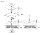
- FIG. 3 is a flow chart showing a method for converting an input power source in accordance with an embodiment of the present invention. Hereinafter, a method for converting an input power source will be described with reference to FIGs. 2 and 3.
- the input power source conversion unit 10 detects a voltage of the adaptor power source 2 (step 10).
- a voltage drop across the resistors R1 and R2 occurs, thereby making the gate voltage of the transistor Q1 to be in HIGH state. Accordingly, a specific power source is determined according to the detected voltage (step 12).
- the transistor Q1 in the battery power supply path turns off and then the battery power supply path is also cut off (step 14).
- the transistor Q1 in the battery power supply path turns on and then the battery power supply path is also in ON state (step 13).
- the detection unit 40 detects the output voltage of the voltage controller 100 (step 30).
- the control unit 30 determines whether the detected voltage is lower than a predetermined voltage (e.g., 12 V ⁇ 10%) or not.
- the predetermined voltage is set to a value capable of breaking an electronic appliance. For example, a TV may operate from about 5V or 12V power supply. If the TV is set to operate from 5V power supply, the predetermined voltage is set to about 12V. If the detected voltage is lower than the predetermined voltage, the control unit 30 controls the output voltage cutoff unit 20 to output the output voltage normally (step 35).
- the control unit 30 transmits a control signal for turning off the transistor Q3 of the output voltage cutoff unit 20 (step 34).
- the control signal may be a LOW level signal.
- the transistor Q3 of the output voltage cutoff unit 20 turns off in response to the control signal (step 36), thereby cutting off the power supply path and the output voltage (step 38).
- FIG. 5 shows a method combining a method shown in FIG. 3 and a method shown in FIG. 4, detailed explanation will be omitted.
- a power supply path corresponding to the detected voltage is selected. Therefore, when a user watches a TV out of doors and then watches the TV in a vehicle or at home again, a power supply path is converted automatically upon connecting an adaptor or cigar jack to the TV. Accordingly, the user doesn't have to convert the power supply path manually.
- an unstable power source e.g., a vehicle cigar jack
- a user can operate the electronic appliance safely because a power supply path is cut off immediately when an over voltage is supplied thereto.
- a TV has been described as an electronic appliance using various types of power sources
- the present invention may be applied to a communication appliance such as a notebook and a home appliance such as an electric cleaner.
- a transistor of p channel type has been described as a transistor of the input power source conversion unit and a transistor of n channel type has been described as a switch of the output voltage cutoff unit, FETS or bipolar transistors of any type can be applied with suitable modifications as necessary.
- FETS or bipolar transistors of any type can be applied with suitable modifications as necessary.
- an embodiment has been described for the case where a circuit cuts off a battery power source and provides an adaptor power source when the battery power source and the adaptor power source are applied simultaneously, the embodiment can be configured again in such a manner that the adaptor power source is cut off and the battery power source is enabled.
Landscapes
- Engineering & Computer Science (AREA)
- Power Engineering (AREA)
- Direct Current Feeding And Distribution (AREA)
Applications Claiming Priority (1)
| Application Number | Priority Date | Filing Date | Title |
|---|---|---|---|
| KR20040079172 | 2004-10-05 |
Publications (2)
| Publication Number | Publication Date |
|---|---|
| EP1684149A2 true EP1684149A2 (de) | 2006-07-26 |
| EP1684149A3 EP1684149A3 (de) | 2007-04-11 |
Family
ID=36125281
Family Applications (1)
| Application Number | Title | Priority Date | Filing Date |
|---|---|---|---|
| EP20050256192 Withdrawn EP1684149A3 (de) | 2004-10-05 | 2005-10-04 | Spannungsregler für ein elektronisches Gerät mit einer Vielzahl von Energiequellen und zugehöriges Verfahren |
Country Status (4)
| Country | Link |
|---|---|
| US (1) | US7663267B2 (de) |
| EP (1) | EP1684149A3 (de) |
| KR (1) | KR100682669B1 (de) |
| CN (1) | CN1767313A (de) |
Families Citing this family (11)
| Publication number | Priority date | Publication date | Assignee | Title |
|---|---|---|---|---|
| US8415928B2 (en) * | 2006-06-30 | 2013-04-09 | System General Corp. | Power circuit |
| KR101260307B1 (ko) * | 2006-09-04 | 2013-05-03 | 삼성전자주식회사 | 전원공급장치 |
| US20100309283A1 (en) * | 2009-06-08 | 2010-12-09 | Kuchar Jr Rodney A | Portable Remote Audio/Video Communication Unit |
| DE102010028569A1 (de) * | 2010-05-04 | 2011-11-10 | BSH Bosch und Siemens Hausgeräte GmbH | Haushaltsgerät und Verfahren zum Betreiben eines Haushaltsgerätes |
| US8618441B2 (en) * | 2010-10-05 | 2013-12-31 | Lincoln Global, Inc. | Output control for auto-reconnect welding/cutting equipment |
| US8400113B2 (en) | 2011-02-11 | 2013-03-19 | Mark Andrew Waring | Battery enhanced, smart grid add-on for appliance |
| CN103970036B (zh) * | 2013-01-29 | 2016-11-23 | 产晶积体电路股份有限公司 | 主动判别用电需求的供电方法 |
| TWI513134B (zh) * | 2014-04-15 | 2015-12-11 | Metalligence Technology Corp | 可攜式能源管理裝置、能源管理模組,以及能源管理方法 |
| JP6578128B2 (ja) * | 2015-05-14 | 2019-09-18 | ローム株式会社 | 電力供給装置、acアダプタ、acチャージャ、電子機器および電力供給システム |
| CN108011498B (zh) * | 2016-10-27 | 2020-04-24 | 比亚迪股份有限公司 | 用于电气设备的供电方法和装置 |
| CN106711934A (zh) * | 2017-02-09 | 2017-05-24 | 昆山龙腾光电有限公司 | 电源保护电路及其控制方法 |
Family Cites Families (12)
| Publication number | Priority date | Publication date | Assignee | Title |
|---|---|---|---|---|
| US3461309A (en) * | 1965-10-18 | 1969-08-12 | Yokogawa Electric Works Ltd | Dc power supply apparatus for supplying a constant voltage to a load |
| US4013938A (en) * | 1974-12-24 | 1977-03-22 | General Electric Company | Power supply system for providing uninterrupted output power |
| US4384214A (en) * | 1981-08-03 | 1983-05-17 | Integrated Switching Supplies, Inc. | Non-interrupting power supplies for loads of less than 500 watts |
| US5196781A (en) * | 1990-09-14 | 1993-03-23 | Weiss Instruments, Inc. | Method and apparatus for power control of solar powered display devices |
| US5465011A (en) * | 1992-12-14 | 1995-11-07 | Square D Company | Uninterruptible power supply with improved output regulation |
| US5825155A (en) * | 1993-08-09 | 1998-10-20 | Kabushiki Kaisha Toshiba | Battery set structure and charge/ discharge control apparatus for lithium-ion battery |
| US5598041A (en) * | 1995-11-16 | 1997-01-28 | Lockheed Martin Corporation | Efficient fault tolerant switching circuit for redundant d. c. power supplies |
| JPH09284994A (ja) | 1996-04-05 | 1997-10-31 | Nec Corp | 過電圧保護回路 |
| EP1433239B1 (de) * | 2000-07-28 | 2016-03-30 | International Power Systems,Inc. | Gleichstrom-gleichstromwandler und leistungssteuerungssystem |
| US6967522B2 (en) * | 2001-04-17 | 2005-11-22 | Massachusetts Institute Of Technology | Adaptive power supply and substrate control for ultra low power digital processors using triple well control |
| US6751109B2 (en) | 2001-10-31 | 2004-06-15 | Mobility Electronics, Inc. | Dual input AC/DC/ battery operated power supply |
| US6785754B1 (en) * | 2003-06-18 | 2004-08-31 | Delta Electronics, Inc. | Integrate serial port plug and play into simple signaling communication type UPS |
-
2005
- 2005-10-04 US US11/242,147 patent/US7663267B2/en not_active Expired - Fee Related
- 2005-10-04 EP EP20050256192 patent/EP1684149A3/de not_active Withdrawn
- 2005-10-04 KR KR1020050092898A patent/KR100682669B1/ko not_active Expired - Fee Related
- 2005-10-08 CN CNA2005101134112A patent/CN1767313A/zh active Pending
Also Published As
| Publication number | Publication date |
|---|---|
| CN1767313A (zh) | 2006-05-03 |
| EP1684149A3 (de) | 2007-04-11 |
| KR100682669B1 (ko) | 2007-02-15 |
| KR20060051994A (ko) | 2006-05-19 |
| US7663267B2 (en) | 2010-02-16 |
| US20060072266A1 (en) | 2006-04-06 |
Similar Documents
| Publication | Publication Date | Title |
|---|---|---|
| US6388468B1 (en) | Circuit and method for operating a MOSFET control circuit with a system operating voltage greater than a maximum supply voltage limit | |
| US7061302B2 (en) | Semiconductor integrated circuit device | |
| EP1684149A2 (de) | Spannungsregler für ein elektronisches Gerät mit einer Vielzahl von Energiequellen und zugehöriges Verfahren | |
| JP2009232495A (ja) | スイッチング電源制御用半導体装置、起動回路、およびスイッチング電源装置の起動方法 | |
| JP5103947B2 (ja) | 突入電流防止回路 | |
| US20110127984A1 (en) | Linear voltage regulator circuit with power saving capability | |
| CN101009469B (zh) | 开关电源控制器及其方法 | |
| US20200228042A1 (en) | Air conditioner | |
| US20100244779A1 (en) | Charging control device and electronic apparatus using same | |
| US20210281105A1 (en) | Circuit device | |
| US20020118060A1 (en) | Power saving circuit for wireless pointer | |
| KR101479076B1 (ko) | 차량 방전 제어 장치 및 실내 정션 박스와, 차량 방전 제어 방법 | |
| US7173350B2 (en) | Load drive control apparatus having minimized power consumption when functioning in waiting status | |
| CN102457168B (zh) | 受控的电压滤波器 | |
| JP2003235260A (ja) | 2重化電源システム | |
| JP2000175449A (ja) | スイッチング電源回路 | |
| CN111169412B (zh) | 车载终端及开关机方法 | |
| US20050202798A1 (en) | Method and circuit arrangement for switching an electronic circuit into a power-saving mode | |
| US20060154709A1 (en) | Two-wire transmitter | |
| CN102096429B (zh) | 反馈稳压装置与方法及其应用的电源转换系统 | |
| CN114825907B (zh) | 一种耐压保护偏置电路和芯片供电电路 | |
| JP2013135580A (ja) | 過電流保護回路及びテレビジョン受信機 | |
| CN119652305A (zh) | 一种用于带电流检测的高边驱动的常电电路 | |
| JPH10126969A (ja) | 電源供給回路 | |
| JP3531605B2 (ja) | 定電圧回路 |
Legal Events
| Date | Code | Title | Description |
|---|---|---|---|
| PUAI | Public reference made under article 153(3) epc to a published international application that has entered the european phase |
Free format text: ORIGINAL CODE: 0009012 |
|
| 17P | Request for examination filed |
Effective date: 20051104 |
|
| AK | Designated contracting states |
Kind code of ref document: A2 Designated state(s): AT BE BG CH CY CZ DE DK EE ES FI FR GB GR HU IE IS IT LI LT LU LV MC NL PL PT RO SE SI SK TR |
|
| AX | Request for extension of the european patent |
Extension state: AL BA HR MK YU |
|
| RIC1 | Information provided on ipc code assigned before grant |
Ipc: G05F 1/56 20060101AFI20070102BHEP |
|
| PUAL | Search report despatched |
Free format text: ORIGINAL CODE: 0009013 |
|
| AK | Designated contracting states |
Kind code of ref document: A3 Designated state(s): AT BE BG CH CY CZ DE DK EE ES FI FR GB GR HU IE IS IT LI LT LU LV MC NL PL PT RO SE SI SK TR |
|
| AX | Request for extension of the european patent |
Extension state: AL BA HR MK YU |
|
| 17Q | First examination report despatched |
Effective date: 20071106 |
|
| AKX | Designation fees paid |
Designated state(s): DE FR GB |
|
| STAA | Information on the status of an ep patent application or granted ep patent |
Free format text: STATUS: THE APPLICATION IS DEEMED TO BE WITHDRAWN |
|
| 18D | Application deemed to be withdrawn |
Effective date: 20120503 |