EP1684256A2 - Appareil d'affichage à plasma et son procédé de commande - Google Patents
Appareil d'affichage à plasma et son procédé de commande Download PDFInfo
- Publication number
- EP1684256A2 EP1684256A2 EP05106557A EP05106557A EP1684256A2 EP 1684256 A2 EP1684256 A2 EP 1684256A2 EP 05106557 A EP05106557 A EP 05106557A EP 05106557 A EP05106557 A EP 05106557A EP 1684256 A2 EP1684256 A2 EP 1684256A2
- Authority
- EP
- European Patent Office
- Prior art keywords
- voltage
- electrode
- electrodes
- cells
- plasma display
- Prior art date
- Legal status (The legal status is an assumption and is not a legal conclusion. Google has not performed a legal analysis and makes no representation as to the accuracy of the status listed.)
- Granted
Links
Images


Classifications
-
- G—PHYSICS
- G09—EDUCATION; CRYPTOGRAPHY; DISPLAY; ADVERTISING; SEALS
- G09G—ARRANGEMENTS OR CIRCUITS FOR CONTROL OF INDICATING DEVICES USING STATIC MEANS TO PRESENT VARIABLE INFORMATION
- G09G3/00—Control arrangements or circuits, of interest only in connection with visual indicators other than cathode-ray tubes
- G09G3/20—Control arrangements or circuits, of interest only in connection with visual indicators other than cathode-ray tubes for presentation of an assembly of a number of characters, e.g. a page, by composing the assembly by combination of individual elements arranged in a matrix no fixed position being assigned to or needed to be assigned to the individual characters or partial characters
- G09G3/22—Control arrangements or circuits, of interest only in connection with visual indicators other than cathode-ray tubes for presentation of an assembly of a number of characters, e.g. a page, by composing the assembly by combination of individual elements arranged in a matrix no fixed position being assigned to or needed to be assigned to the individual characters or partial characters using controlled light sources
- G09G3/28—Control arrangements or circuits, of interest only in connection with visual indicators other than cathode-ray tubes for presentation of an assembly of a number of characters, e.g. a page, by composing the assembly by combination of individual elements arranged in a matrix no fixed position being assigned to or needed to be assigned to the individual characters or partial characters using controlled light sources using luminous gas-discharge panels, e.g. plasma panels
- G09G3/288—Control arrangements or circuits, of interest only in connection with visual indicators other than cathode-ray tubes for presentation of an assembly of a number of characters, e.g. a page, by composing the assembly by combination of individual elements arranged in a matrix no fixed position being assigned to or needed to be assigned to the individual characters or partial characters using controlled light sources using luminous gas-discharge panels, e.g. plasma panels using AC panels
- G09G3/291—Control arrangements or circuits, of interest only in connection with visual indicators other than cathode-ray tubes for presentation of an assembly of a number of characters, e.g. a page, by composing the assembly by combination of individual elements arranged in a matrix no fixed position being assigned to or needed to be assigned to the individual characters or partial characters using controlled light sources using luminous gas-discharge panels, e.g. plasma panels using AC panels controlling the gas discharge to control a cell condition, e.g. by means of specific pulse shapes
- G09G3/294—Control arrangements or circuits, of interest only in connection with visual indicators other than cathode-ray tubes for presentation of an assembly of a number of characters, e.g. a page, by composing the assembly by combination of individual elements arranged in a matrix no fixed position being assigned to or needed to be assigned to the individual characters or partial characters using controlled light sources using luminous gas-discharge panels, e.g. plasma panels using AC panels controlling the gas discharge to control a cell condition, e.g. by means of specific pulse shapes for lighting or sustain discharge
-
- G—PHYSICS
- G09—EDUCATION; CRYPTOGRAPHY; DISPLAY; ADVERTISING; SEALS
- G09G—ARRANGEMENTS OR CIRCUITS FOR CONTROL OF INDICATING DEVICES USING STATIC MEANS TO PRESENT VARIABLE INFORMATION
- G09G3/00—Control arrangements or circuits, of interest only in connection with visual indicators other than cathode-ray tubes
- G09G3/20—Control arrangements or circuits, of interest only in connection with visual indicators other than cathode-ray tubes for presentation of an assembly of a number of characters, e.g. a page, by composing the assembly by combination of individual elements arranged in a matrix no fixed position being assigned to or needed to be assigned to the individual characters or partial characters
- G09G3/22—Control arrangements or circuits, of interest only in connection with visual indicators other than cathode-ray tubes for presentation of an assembly of a number of characters, e.g. a page, by composing the assembly by combination of individual elements arranged in a matrix no fixed position being assigned to or needed to be assigned to the individual characters or partial characters using controlled light sources
- G09G3/28—Control arrangements or circuits, of interest only in connection with visual indicators other than cathode-ray tubes for presentation of an assembly of a number of characters, e.g. a page, by composing the assembly by combination of individual elements arranged in a matrix no fixed position being assigned to or needed to be assigned to the individual characters or partial characters using controlled light sources using luminous gas-discharge panels, e.g. plasma panels
- G09G3/288—Control arrangements or circuits, of interest only in connection with visual indicators other than cathode-ray tubes for presentation of an assembly of a number of characters, e.g. a page, by composing the assembly by combination of individual elements arranged in a matrix no fixed position being assigned to or needed to be assigned to the individual characters or partial characters using controlled light sources using luminous gas-discharge panels, e.g. plasma panels using AC panels
- G09G3/296—Driving circuits for producing the waveforms applied to the driving electrodes
-
- G—PHYSICS
- G09—EDUCATION; CRYPTOGRAPHY; DISPLAY; ADVERTISING; SEALS
- G09G—ARRANGEMENTS OR CIRCUITS FOR CONTROL OF INDICATING DEVICES USING STATIC MEANS TO PRESENT VARIABLE INFORMATION
- G09G2300/00—Aspects of the constitution of display devices
- G09G2300/04—Structural and physical details of display devices
- G09G2300/0421—Structural details of the set of electrodes
- G09G2300/0426—Layout of electrodes and connections
-
- G—PHYSICS
- G09—EDUCATION; CRYPTOGRAPHY; DISPLAY; ADVERTISING; SEALS
- G09G—ARRANGEMENTS OR CIRCUITS FOR CONTROL OF INDICATING DEVICES USING STATIC MEANS TO PRESENT VARIABLE INFORMATION
- G09G2310/00—Command of the display device
- G09G2310/06—Details of flat display driving waveforms
- G09G2310/066—Waveforms comprising a gently increasing or decreasing portion, e.g. ramp
Definitions
- the present invention relates to a plasma display and a driving method thereof.
- a plasma display is a display device that uses plasma generated by gas discharge in discharge cells to display characters or images.
- a plasma display panel (PDP) of the plasma display includes more than several tens to millions of pixels arranged in a matrix pattern.
- One frame of the plasma display is divided into a plurality of subfields, and each subfield includes: a reset period, an address period, and a sustain period.
- the reset period is for initializing the status of each discharge cell so as to facilitate an addressing operation on the discharge cell.
- the address period is for selecting turn-on/turn-off cells among the discharge cells, and the sustain period is for causing the turn-on cells to continue discharge for displaying an image.
- sustain pulses are alternately applied to scan electrodes and sustain electrodes during the sustain period, and reset waveforms and address waveforms are applied to the scan electrodes during the reset period and the address period. Therefore, a scan driving board for driving the scan electrodes and a sustain driving board for driving the sustain electrodes are separately needed. Mounting the two separate driving boards on a chassis base may generate problems and increase the overall cost of the device.
- the scan driving board supplies driving waveforms of the reset period and the address period, the magnitude of the impedance component formed on the scan driving board is different from that formed on the sustain driving board. Accordingly, the waveform of the sustain pulse applied to the scan electrode is different from that applied to the sustain electrode in the sustain period.
- the present invention provides a plasma display and a driving method thereof for preventing distortion of a sustain pulse.
- the present invention also provides a plasma display for reducing or eliminating a driving board for driving a sustain electrode.
- An exemplary embodiment of the present invention discloses a driving method of a plasma display.
- the plasma display includes: a first electrode, a second electrode, a third electrode which extends substantially perpendicular to the first and second electrodes, and a cell.
- the cell corresponds to an intersection of the first, second, and third electrodes.
- the driving method includes: gradually reducing a voltage of the first electrode from a first voltage to a second voltage; applying a scan pulse and an address pulse to the first and third electrodes of a cell, respectively, to set the cell receiving the scan pulse and the address pulse to a turn-off cell; and applying a sustain pulse alternatively having a third voltage lower than a fourth voltage and a fifth voltage higher than the fourth voltage to the first electrode while applying the fourth voltage to the second electrode.
- the plasma display includes: a PDP, a controller, and a driver.
- the PDP includes: a plurality of first electrodes, a plurality of second electrodes, a plurality of third electrodes, and a plurality of cells, the third electrode extending substantially perpendicular to the first and second electrodes, the cell corresponding to an intersection of the first electrode, the second electrode and the third electrode.
- the controller controls the driving of the PDP.
- the driver performs an address period for discharging cells to be set to turn-off cells among a plurality of turn-on cells, and performs a sustain period for applying a sustain pulse to the first electrodes to sustain-discharge turn-on cells while applying a first voltage to the second electrodes.
- the display further comprises a driver for performing a reset period for initializing the states of the plurality of cells to the turn-on cells before performing the address period.
- the sustain pulse alternatively has a second voltage lower than the first voltage and a third voltage higher than the first voltage, and the driver gradually reduces the voltage of the first electrodes from a fourth voltage to a fifth voltage higher than the second voltage to initialize the plurality of cells during the reset period.
- a difference between the first voltage and the second voltage is equal to a difference between the third voltage and the first voltage.
- the driver respectively applies a scan pulse and an address pulse to the first electrode and the third electrode of the cell to be set to the turn-off cell.
- a voltage of the scan pulse is equal to or lower than the fifth voltage, and a voltage of the address pulse is higher than the first voltage.
- the driver applies the first voltage to the second electrodes during the reset and address periods and the first voltage is a ground voltage.
- Still another exemplary embodiment of the present invention discloses a driving method of a plasma display.
- the plasma display includes: a plurality of first electrodes, a plurality of second electrodes, a plurality of third electrodes and a plurality of cells, and displays an image during a frame.
- the third electrode extends substantially perpendicular to the first and second electrodes.
- the cell is formed by the first, second, and third electrodes, and the frame is divided into a plurality subfields.
- the driving method includes: initializing the plurality of cells to turn-on cells; discharging cells to be set to turn-off cells among the plurality of cells; and applying sustain pulses to the first electrodes to sustain-discharge turn-on cells while applying a first voltage to the second electrodes.
- the driving method includes: discharging cells to be set to turn-off cells among the cells sustain-discharged in the first subfield; and applying the sustain pulses to the first electrodes to sustain-discharge the turn-on cells while applying the first voltage to the second electrodes.
- the driving method is further comprising applying the first voltage to the second electrodes during initializing of the plurality of cells and discharging the cells to be set to the turn-off cells.
- a driving method of a plasma display including: gradually reducing the voltage of the first electrodes from a first voltage to a second voltage; selecting turn-off cells or turn-on cells among the plurality of cells through address discharge; and applying a sustain pulse alternatively having a third voltage lower than a fourth voltage and a fifth voltage higher than the fourth voltage to the first electrodes while applying the fourth voltage to the second electrodes.
- the cell in which the address discharge is generated is set to the turn-off cell.
- the driving method is further comprising applying the fourth voltage to the second electrodes during gradually reducing the voltage of the first electrodes and selecting the turn-off cells or the turn-on cells.
- a plasma display disclosed in a yet further exemplary embodiment includes: a PDP, a chassis base, a control board, and a driving board.
- the PDP includes: a plurality of first electrodes, a plurality of second electrodes, a plurality of third electrodes, and a plurality of cells, the third electrode extending substantially perpendicular to the first and second electrodes, the cell corresponding to an intersection of the first electrode, the second electrode and the third electrode.
- the chassis base is opposite to the PDP.
- the control board is formed on the chassis base and divides a frame for displaying an image into a plurality of subfields.
- the driving board is formed on the chassis base, applies a driving waveform displaying the image on the PDP to the first and third electrodes, biases the second electrodes at a first voltage, and performs an address period for address-discharging cells to be set to turn-off cells among turn-on cells and a sustain period for sustain-discharging turn-on cells, in the respective subfields.
- the plasma display further comprises a driving board for performing a reset period for initializing the plurality of cells to turn-on cells in a first subfield of the plurality of subfields.
- the first subfield is positioned at the head of the frame.
- the driving board address-discharges cells to be set to turn-off cells among the cells sustain-discharged in a previous subfield during the address period of second subfield.
- the plasma display further comprises a driving board for gradually reducing a voltage of the first electrodes from a second voltage to a third voltage during the reset period, and applying a sustain pulse alternately having a fourth voltage lower than the third voltage and a fifth voltage higher than the first voltage to the first electrodes during the sustain period.
- the plasma display further comprises a driving board for initially applying the fourth voltage to the first electrodes in the sustain period, and applying the fifth voltage to the first electrodes to perform a last sustain-discharge in the sustain period.
- a still further exemplary embodiment discloses a plasma display including a PDP, a chassis base, a control board, and first and second driving boards.
- the PDP includes: a plurality of first electrodes, a plurality of second electrodes, a plurality of third electrodes, and the third electrode extends substantially perpendicular to the first and second electrodes.
- the chassis base is opposite an image display side of the PDP and biases the second electrodes at a constant voltage.
- the first and second driving boards are formed on the chassis base, and apply first and second driving waveforms displaying the image to the first and second electrodes, respectively.
- the control board is formed on the chassis base, and controls the first and second driving boards. No driving board for driving the second electrodes by control of the control board is formed on the chassis base.
- a cell corresponds to an intersection of a respective first electrode, second electrode and third electrode
- the plasma display further comprises a the first driving board and the second driving board for sustain-discharging turn-on cells to display the image after setting turn-off cells among the turn-on cells through a discharge.
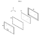
- FIG. 1 shows an exploded perspective view of a plasma display according to an exemplary embodiment of the present invention.
- FIG. 2 shows a schematic view of a plasma display panel according to an exemplary embodiment of the present invention.
- FIG. 3 shows a plan view of a chassis base of a plasma display according to an exemplary embodiment of the present invention.
- FIG. 4 shows a driving waveform of the plasma display according to a first exemplary embodiment of the present invention.
- FIG. 5 shows the wall charge state of a cell after a reset period ends.
- FIG. 6 shows a driving waveform of the plasma display according to a second exemplary embodiment of the present invention.
- FIG. 7A, FIG. 7B, FIG. 7C, and FIG. 7D show the wall charge conditions of a cell according to the driving waveforms of FIG. 6, respectively.
- FIG. 8 shows a driving waveform of the plasma display according to a third exemplary embodiment of the present invention.
- FIG. 9 shows a driving method of the plasma display according to a third exemplary embodiment of the present invention.
- FIG. 10 shows a driving waveform of the plasma display according to a fourth exemplary embodiment of the present invention.
- the plasma display includes: a PDP 10, a chassis base 20, a front case 30, and a rear case 40.
- the chassis base 20 is coupled to the plasma display panel 10 opposite an image display side of the plasma display panel 10.
- the front case 30 is coupled to the plasma display panel 10 on the image display side of the plasma display panel 10.
- the rear case 40 is coupled to the chassis base 20. The assembly of these parts forms a plasma display.
- the PDP 10 of FIG. 1 includes: a plurality of address (A) electrodes A1 to Am extending in a column direction, and a plurality of scan (Y) electrodes Y1 to Yn and a plurality of sustain (X) electrodes X1 to Xn each extending in a row direction.
- the respective sustain electrodes X1 to Xn correspond to the respective scan electrodes Y1 to Yn.
- the sub-pixel area delineating a discharge space where the A electrodes cross the Y and X electrodes forms a discharge cell 12.
- driving boards 100, 200, 300, 400, 500 for driving the PDP 10 are formed on the chassis base 20.
- Address buffer boards 100 are formed on a top and a bottom of the chassis base 20.
- the configuration shown is considered a dual driving scheme, providing address voltages from both top and bottom sides of the chassis 20, and may be altered depending on the driving scheme.
- the address buffer boards 100 may be located on either the top or the bottom of the chassis base 20.
- the address buffer board 100 may be formed as a single board or a combination of a plurality of boards.
- the address buffer board 100 receives an address driving control signal from a control board 400 and applies a voltage for selecting a turn-on cell (or a turn-off cell) to the appropriate A electrodes.
- the X electrodes are biased at a constant reference voltage.
- a scan driving board 200 is located to the left of the chassis base 20 and is coupled to the Y electrodes through a scan buffer board 300. During an address period, the scan buffer board 300 applies a voltage to the Y electrodes for sequentially selecting scan electrodes Y1 to Yn.
- the scan driving board 200 receives a driving signal from the control board 400 and applies a driving voltage to the Y electrodes. While, in FIG. 3, the scan driving board 200 and the scan buffer board 300 are shown on the left side of the chassis base 20, they may be located on the right side of the chassis base 20. Also, the scan buffer board 300 and the scan driving board 200 may be combined together as one integral part.
- control board 400 Upon receiving an external image signal, the control board 400 generates a control signal for driving the A electrodes and a control signal for driving the Y and X electrodes. The control board 400 subsequently applies the control signals to the address buffer board 100, the scan driving board 200, and the scan buffer board 300.
- a power supply board 500 supplies the power for driving the plasma display. The control board 400 and the power supply board 500 are located on a central area of the chassis base 20.
- the address buffer board 100, the scan driving board 200 and the scan buffer board 300 are operated as a driver of the PDP 10.
- the control board 400 is operated as a controller of the PDP 10.
- the power supply board 500 is operated as a power source of the PDP 10.
- FIG. 4 shows a driving waveform of the plasma display according to a first exemplary embodiment of the present invention.
- driving waveforms applied to a Y electrode, an X electrode, and an A electrode are exemplarily described in connection with only one cell 12 (FIG. 2).
- the Y electrode receives a voltage from the scan driving board 200 and the scan buffer board 300
- the A electrode receives a voltage from the address buffer board 100.
- the X electrode is biased at the constant reference voltage, represented as a ground voltage (0V) in FIG. 4.
- the plasma display is driven during frames and frames are divided into subfields.
- one subfield of the driving waveform is divided into three periods, the reset period, the address period, and the sustain period.
- the reset period has a rising period and a falling period.
- the voltage of the Y electrode is gradually increased from a voltage Vs to a voltage Vset while the A electrode is maintained at a reference voltage 0V.
- the voltage of the Y electrode increases in a ramp between voltage Vs and voltage Vset.
- a weak discharge is generated between the Y and X electrodes and between Y and A electrodes, and (-) wall charges are formed on the Y electrode and (+) wall charges are formed on the X and A electrodes.
- a weak discharge is caused in a cell 12 (FIG. 2), and accordingly, wall charges are formed such that a sum of an externally applied voltage and a wall voltage may be maintained at a discharge firing voltage.
- Wall charges being described in the present invention refer to charges formed on a wall of a discharge cell 12 (FIG. 2) close to each electrode (X, Y, or A) and accumulated on the electrode.
- the wall charge is described as being “formed” or “accumulated” on the electrode (X, Y, or A) although the wall charges do not actually touch the electrodes.
- a wall voltage Vw means a potential difference formed between the walls of the discharge cell 12 (FIG. 2) by the wall charges.
- the voltage Vset is a voltage high enough to fire a discharge in cells 12 of any condition because every cell 12 (FIG. 2) has to be initialized during the reset period.
- the voltage Vs is equal to the voltage applied to the Y electrode during the sustain period, and is less than a voltage required for firing discharge between the Y electrode and X electrode.
- the voltage of the Y electrode is gradually reduced from the voltage Vs to a voltage Vnf1 while the voltage of the A electrode is maintained at the reference voltage.
- a weak discharge is generated between the Y and X electrodes and between the Y and A electrodes while the voltage of the Y electrode is reduced, and accordingly, the (-) wall charges formed on the Y electrode and the (+) wall charges formed on the X and A electrodes are eliminated.
- the voltage Vnf1 is set to be close to a discharge firing voltage between the Y and X electrodes. Then, a wall voltage between the Y and X electrodes reaches near 0V, and therefore, a cell 12 (FIG. 2) that was not addressed with an address discharge during the address period may be prevented from misfiring during the sustain period.
- the wall voltage between the Y and A electrodes is determined by the magnitude of Vnf1 because the voltage of the A electrode is maintained at the reference voltage 0V.
- a scan pulse VscL1 and an address pulse Va are applied to the Y electrode and the A electrode of the turn-on cell 12 (FIG. 2), respectively.
- a non-selected Y electrode is biased at a voltage VscH which is higher than VscL1, and the reference voltage is applied to the A electrode of the cell being turned off.
- the scan buffer board 300 selects a Y electrode to be applied with the scan pulse of VscL1, among the scan electrodes Y1 to Yn.
- the Y electrodes may be selected in an order of arrangement of the Y electrodes in the column direction.
- the address buffer board 100 selects cells 12 to be turned on among the cells along the selected Y electrode. That is, the address buffer board 100 selects the A electrodes to which the address pulse of the voltage Va is applied among the address electrodes A1 to Am.
- the scan pulse in the form of the voltage VscL1, is first applied to the Y electrode in the first row (Y1).
- the address pulse in the form of the voltage Va, is applied to the A electrode on the cells 12 to be turned on along the first row.
- a discharge is generated between the Y electrode in the first row (Y1) and the A electrode receiving the voltage Va.
- (+) wall charges are formed on the Y electrode and (-) wall charges are formed on the A electrode and X electrode.
- a wall voltage Vwxy1 is formed between the X and Y electrodes with the potential of the wall adjacent the Y electrode higher than the potential of the wall adjacent the X electrode.
- the scan voltage in the form of the voltage VscL1
- the address pulse in the form of the voltage Va
- the address discharge is generated in the cells 12 crossed by the A electrodes receiving the voltage Va and the Y electrode in the second row (Y2) and accordingly, wall charges are formed in those cells 12 in the manner described above.
- wall charges are formed in cells 12 to be turned on in the same manner as described above, i.e., by applying the address pulse, the voltage Va, to A electrodes on cells to be turned on 12 while sequentially applying a scan pulse, voltage VscL1, to the Y electrodes from the first row (Y1) to the last row (Yn).
- the voltage VscL1 is usually set to be equal to or lower than the voltage Vnf1, and the voltage Va is usually set to be higher than the reference voltage.
- Generation of address discharge by applying the voltage Va to the A electrode will now be described in connection with the case that the voltage VscL1 equals the voltage Vnf1.
- the voltage Vfay is formed between the A and Y electrodes, and accordingly generation of a discharge may be expected.
- the expected discharge is not generated because a discharge delay is greater than the width of the scan pulse and the address pulse.
- the voltage difference between the electrodes A and Y is increased as the magnitudes of Va and VscL1 are increased, because Va is positive and VscL1 is negative and an increase in their magnitudes means a greater voltage difference between them.
- generation of the address discharge may be facilitated by setting the voltage VscL1 to be lower than the voltage Vnf1.
- a sustain discharge is generated between the Y and X electrodes by initially applying a pulse, in the form of the voltage Vs, to the Y electrode.
- the wall voltage Vwxy1 is formed such that the potential of the Y electrode is higher than the X electrode in the cells 12 having undergone the address discharge in the address period.
- the voltage Vs is set to be lower than the discharge firing voltage Vfxy, while the sum of the voltages Vs+Vwxy1 is set to be higher than the voltage Vfxy.
- the positive wall voltage Vwxy1 from the Y electrode to the X electrode, existing before the application of Vs does not generate a discharge.
- the sum of these two generally positive voltages will reach above the required firing voltage discharge between X and Y electrodes and a discharge is sustained.
- the (-) wall charges are formed on the Y electrode and the (+) wall charges are formed on the X and A electrodes, such that the potential of the X electrode wall is higher than the Y electrode wall.
- the voltage Vwyx1 is formed such that the potential of the Y electrode itself, and not its adjacent wall, becomes higher than the X electrode itself, a pulse of a negative voltage -Vs is applied to the Y electrode to fire a subsequent sustain discharge.
- (+) wall charges are formed on the Y electrode and (-) wall charges are formed on the X and A electrodes such that another sustain discharge may be generated by applying the positive voltage Vs to the Y electrode.
- the process of alternately applying the sustain pulses of Vs and -Vs to the Y electrode is repeated a number of times corresponding to a weight value of a corresponding subfield.
- reset, address, and sustain operations may be performed by a driving waveform applied only to the Y electrode while the X electrode is biased at the reference voltage. Accordingly, a driving board for driving the X electrode is not required and the X electrode may stay simply biased at a reference voltage, for example at 0V. Since the sustain pulses are only supplied from the scan driving board 200, the impedance formed by the voltage Vs applied to the Y electrode is substantially same as that by the voltage -Vs applied to the Y electrode.
- a constant positive voltage may be applied to the X electrode during the falling period of the reset period and the address period. Then, since a sustain driving board which only has an element for transmitting the constant positive voltage is formed on the chassis base 20, the sustain driving board can be minimized.
- the rising start voltage of the Y electrode of the rising period and the falling start voltage of the Y electrode of the falling period are respectively set to the voltage Vs in the first exemplary embodiment of the present invention
- another voltage may be used for the rising start voltage or the falling start voltage. If the discharge of the cells starts in the rising period when the voltage of the Y electrode is a voltage higher than the voltage Vs, the rising start voltage of the Y electrode may be set to the voltage higher than the voltage Vs. Then, the rising period will be shorter. In the same manner, if the discharge of the cells starts in the falling period when the voltage of the Y electrode is a voltage lower than the voltage Vs, the falling start voltage of the Y electrode may be set to the voltage lower than the voltage Vs. Then, the falling period will be shorter. In addition, a voltage lower than the voltage Vs may be used for the rising start voltage, and a voltage higher than the voltage Vs may be used for the falling start voltage.
- the final voltage Vnf1 that is a voltage applied to the Y electrode during the falling period of the reset period, may be near the discharge firing voltage, Vfxy, between the Y and X electrodes. If the discharge firing voltage Vfay between the Y and A electrodes is less than discharge firing voltage Vfxy between the Y and X electrodes, the (+) wall charges will be formed on the Y electrode and the (-) wall charge will be formed on the A electrode at the final voltage Vnf of the falling period, as shown in FIG. 5. That is, a wall potential of the Y electrode with respect to the A electrode may be a positive voltage at the final voltage Vnf of the falling period.
- the discharge may be generated between the Y and A electrodes by a difference between external voltages applied to the Y and A electrodes and a wall voltage between the Y and A electrodes. That is, the turn-off cell may be discharged in the sustain period.
- An exemplary embodiment for preventing this misfiring discharge will be described with reference to FIG. 6 and FiGs. 7A to 7D.
- FIG. 6 shows a driving waveform of the plasma display according to a second exemplary embodiment of the present invention
- FiGs. 7A to 7D respectively shows wall charge conditions of a cell according to the driving waveforms of FIG. 6.
- FIG. 7A shows the wall charge condition of the cell at the time that the falling period of the reset period ends.
- FIG. 7B shows the wall charge condition of the cell at the time after an address discharge is generated in the cell.
- FIG. 7C shows the wall charge condition of the cell at the time after a first sustain-discharge is generated in the cell.
- FIG. 7D shows the wall charge condition of the cell at the time after a second sustain-discharge is generated in the cell.
- the driving waveform according to the second exemplary embodiment of the present invention is similar to the first exemplary embodiment.
- the voltage of Y electrode is gradually reduced from the voltage Vs to the voltage Vnf2 higher than the voltage Vnf1.
- Vnf2 the voltage of the Y electrode
- a predetermined amount of the (+) wall charges are remained on the Y electrode
- a predetermined amount of the (+) wall charges are remained on the X and A electrodes as shown in FIG. 7A.
- the wall voltage Vwxy2 which is formed between the Y and X electrodes with the potential of the wall adjacent the X electrode higher than the potential of the wall adjacent the Y electrode is given by Equation 1 below.
- the voltage Vnf2 is set such that a sum of the wall voltage Vwxy2 and the voltage Vs is higher than the discharge firing voltage Vfxy between the X and Y electrodes as expressed in Equation 2 below.
- V f x y V w x y 2 + V s V f x y + V n f 2 + V s
- the voltage Vnf2 is set to be higher than the voltage -Vs as expressed in Equation 3 below [ Equation 3 ] V n f 2 ⁇ V s Then, the all cells are set to the turn-on cells in the reset period. That is, when the voltage -Vs is applied to the Y electrode in the sustain period, the sustain-discharge is generated in the cell on which the wall voltage Vwxy2 is formed.
- a scan pulse VscL2 and an address pulse Va are applied to the Y electrode and the A electrode of the turn-off cell 12 (FIG. 2), respectively.
- an address discharge is generated between the Y electrode receiving the voltage VscL2 and the A electrode receiving the voltage Va. Accordingly, wall charges formed on the Y, X, and A electrode of the cell are eliminated as shown in FIG. 7B. That is, due to a discharge between the Y and A electrodes following a discharge between the Y and A electrodes, the wall charges formed on the Y, X, and A electrode of the cell so that the cell is set to the turn-off cell.
- a non-selected Y electrode is biased at the voltage VscH which is higher than the voltage VscL2, and the reference voltage is applied to the A electrode of the cell being turned on. Then, the turn-on cell not having undergone the address discharge maintains the state shown in FIG. 7A.
- a pulse in the form of the voltage - Vs, is initially applied to the Y electrode since the potential of the X electrode wall is higher than the Y electrode wall in the turn-on cells not having undergone the address discharge in the address period. Since the wall voltage Vwxy2 is set to satisfy Equation 2, the sustain-discharge is generated between the X and Y electrodes of the turn-on cell such that the (-) wall charges are formed on the X electrode and the (+) wall charges are formed on the Y electrode as shown in FIG. 7C.
- the misfiring discharge is not generated between the Y and A electrodes when the voltage -Vs or Vs is applied to the Y electrode because the wall charges formed on the Y and A electrodes are almost eliminated in the turn-off cells having undergone the address discharge in the address period.
- the process of alternately applying the sustain pulses of -Vs and Vs to the Y electrode is repeated a number of times corresponding to a weight value of a corresponding subfield.
- the cell having undergone the address discharged is set to the turn-off cell in the address period. That is, since the address operation for eliminating the wall charges is performed in the address period, the final voltage Vnf2 of the reset period is set to higher than the voltage Vnf1 of the first exemplary embodiment. As a result, the misfiring discharge is not generated in the turn-off cell in the sustain period.
- the waveform shown in FIG. 6 may be applied to the Y, X, and A electrodes in each of the plurality of subfields forming one frame. Then, the cell, which is turned off during one frame and represents 0 gray scale (black gray scale), becomes too bright. That is, since the weak discharge of the reset period and the address discharge of the address period are generated in the turn-off cell during the plurality of subfield forming one frame, the turn-off cell dose not represent the black color.
- An exemplary embodiment for minimizing the discharge of the turn-off cell will be described with reference to FIG. 8 and FIG. 9.
- FIG. 8 shows a driving waveform of the plasma display according to a third exemplary embodiment of the present invention
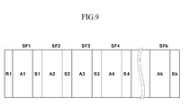
- FIG. 9 shows a driving method of the plasma display according to a third exemplary embodiment of the present invention.
- the three subfields SF1, SF2, SF3 of the plurality of subfields are shown in FIG. 8, and the plurality of subfields SF1 to SFk forming one frame are shown in FIG. 9.
- the first subfield SF1 includes: the reset period R1, the address period A1, and the sustain period S1.
- the subfields SF2 and SF3 following the first subfield SF1 include the address period A2 and A3, and the sustain periods S2 and S3, respectively.
- the reset period R1, the address periods A1 to A3, and the sustain periods S1 to S3 respectively correspond to those described in the second exemplary embodiment, and the sustain period S1 to S3 end after the voltage Vs is applied to the Y electrode such that the last sustain-discharge is generated.
- the cell which is set to the turn-off cell in the first subfield SF1 and has the cell state shown in FIG. 7B, is maintained to the turn-off cell in the subsequent subfields SF2 and SF3. That is, in the cell where the wall charges have been eliminated during the address period A1 of the first subfield SF1, the address discharge cannot be generated during the address periods A2 and A3 of the subsequent subfields SF2 and SF3.
- the turn-on cell has the cell state of FIG. 7D which is similar to the cell state of FIG. 7A, and therefore, the address discharge can be generated in this cell during the address period A2 of the subsequent subfield SF2.
- the address discharge is generated in the cell during the address period A2 of the second subfield SF2 such that this cell is set to the turn-off cell in the second subfield SF2 and does not sustain-discharge from the second subfield SF2.
- this cell is set to the turn-on cell in the second subfield SF2 and can be set to the turn-off cell according to the address discharge in the subsequent subfield SF3.
- the address discharge can be generated in the only cell which is set to the turn-on cell in the previous subfield. Therefore, if the first subfield is set to a subfield having the reset period and the remaining subfields are set to subfields not having the reset period in one frame, the discharge is generated during the reset period and the address period of the first subfield only when the 0 gray scale (black gray scale) is represented. That is, the contrast ratio can be improved since the discharge is not generated in the remained subfields when the black gray scale is represented.
- the cell in which the address discharge is generated in the first subfield 1 F represents 0 gray scale. Since the cell in which the address discharge is generated in the i th subfield represents is set to the turn-on cell from the first subfield 1 F to the (i-1) th subfield, this cell represents (i-1) gray scale (where 'i' is an integer more than 1). Therefore, 0 to (k-1) gray scales are represented when one frame is divided into k subfields. However, since a period of one frame is limited, the number of the subfields forming one frame is limited, and therefore, the number of gray scales is limited. Therefore, the halftoning method such as a dithering method or an error diffusion method may be applied to the gray scales represented by a combination of the plurality of subfields so that the number of the gray scales increases.
- the halftoning method such as a dithering method or an error diffusion method may be applied to the gray scales represented by a combination of the plurality of subfields so that the number
- the voltage of the Y electrode is increased from the voltage Vs to the voltage -Vs and is reduced from the voltage -Vs to the voltage Vs during the sustain period.
- the electro magnetic interference (EMI) may be greatly generated by the voltage variance corresponding to 2Vs.
- the reactive power is consumed by the capacitance component formed by the X and Y electrodes. Since the reactive power is proportional to a square of the voltage variance 2Vs, i.e., (2Vs) 2 the reactive power consumption is high.
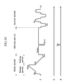
- FIG. 10 shows driving waveforms of the plasma display according to a fourth exemplary embodiment of the present invention.
- the driving waveform according to the fourth exemplary embodiment is similar to the second exemplary embodiment.
- the voltage of the Y electrode is increased from 0V to the voltage Vs after rising from the voltage -Vs to 0V during the sustain period.
- the voltage of the Y electrode is reduced from 0V to the voltage -Vs after being reduced from the voltage Vs to 0V during the sustain period.
- the EMI can be reduced since the voltage variance of the Y electrode corresponds to the voltage Vs.
- the reactive power is proportional to two times a square of the voltage variance, i.e., 2(Vs) 2 . That is, the reactive power can be reduced to the half of the reactive power of the case where the voltage of the Y electrode is directly changed from the voltage -Vs to the voltage Vs.
- the voltage of the Y electrode may be changed in two steps only when the voltage of the Y electrode is increased, or the voltage of the Y electrode may be changed in two steps only when the voltage of the Y electrode is reduced.
- the voltage of the Y electrode may be changed from the voltage -Vs to the voltage Vs through a voltage different from 0V, and may be changed in more than two steps.
- the voltage of the Y electrode has been described to be gradually changed in a ramp in the first to fourth exemplary embodiments, the voltage of the Y electrode may be gradually changed in the other form.
- the impedance on the path for applying the sustain pulse of the voltage Vs may be substantially same as the impedance on the path for applying the sustain pulse of the voltage -Vs because the sustain pulse is supplied from the scan driving board.
- a board for driving the X electrode may be eliminated because the X electrode is biased at the constant voltage. As a result, the cost for manufacturing the plasma display may be reduced.
- the misfiring discharge of the sustain period may be prevented because the address discharge for eliminating the wall charges is generated in the address period.
Landscapes
- Engineering & Computer Science (AREA)
- Physics & Mathematics (AREA)
- Power Engineering (AREA)
- Plasma & Fusion (AREA)
- Computer Hardware Design (AREA)
- General Physics & Mathematics (AREA)
- Theoretical Computer Science (AREA)
- Control Of Indicators Other Than Cathode Ray Tubes (AREA)
- Control Of Gas Discharge Display Tubes (AREA)
Applications Claiming Priority (1)
| Application Number | Priority Date | Filing Date | Title |
|---|---|---|---|
| KR1020050006608A KR100590016B1 (ko) | 2005-01-25 | 2005-01-25 | 플라즈마 표시 장치 및 그 구동 방법 |
Publications (3)
| Publication Number | Publication Date |
|---|---|
| EP1684256A2 true EP1684256A2 (fr) | 2006-07-26 |
| EP1684256A3 EP1684256A3 (fr) | 2006-08-23 |
| EP1684256B1 EP1684256B1 (fr) | 2008-09-10 |
Family
ID=36061630
Family Applications (1)
| Application Number | Title | Priority Date | Filing Date |
|---|---|---|---|
| EP05106557A Expired - Lifetime EP1684256B1 (fr) | 2005-01-25 | 2005-07-18 | Appareil d'affichage à plasma et son procédé de commande |
Country Status (6)
| Country | Link |
|---|---|
| US (1) | US20060164334A1 (fr) |
| EP (1) | EP1684256B1 (fr) |
| JP (1) | JP2006209078A (fr) |
| KR (1) | KR100590016B1 (fr) |
| CN (1) | CN1811875A (fr) |
| DE (1) | DE602005009650D1 (fr) |
Families Citing this family (7)
| Publication number | Priority date | Publication date | Assignee | Title |
|---|---|---|---|---|
| WO2008047410A1 (fr) * | 2006-10-17 | 2008-04-24 | Hitachi Plasma Display Limited | Procédé de pilotage d'écran plasma et appareil à écran plasma |
| WO2008047411A1 (fr) * | 2006-10-17 | 2008-04-24 | Hitachi Plasma Display Limited | Procédé de pilotage d'écran plasma et appareil à écran plasma |
| WO2008047409A1 (fr) * | 2006-10-17 | 2008-04-24 | Hitachi Plasma Display Limited | Procédé de pilotage d'écran plasma et appareil à écran plasma |
| WO2008053510A1 (fr) * | 2006-10-27 | 2008-05-08 | Hitachi, Ltd. | Procédé pour faire fonctionner un panneau d'affichage plasma et dispositif d'affichage plasma |
| WO2008050454A1 (fr) * | 2006-10-27 | 2008-05-02 | Hitachi Plasma Display Limited | Écran plasma et son procédé de pilotage |
| JP4561734B2 (ja) | 2006-12-13 | 2010-10-13 | 株式会社日立製作所 | 半導体装置およびそれを用いたプラズマディスプレイ装置 |
| KR100823488B1 (ko) * | 2007-01-19 | 2008-04-21 | 삼성에스디아이 주식회사 | 플라즈마 표시 장치 및 그 구동 방법 |
Citations (2)
| Publication number | Priority date | Publication date | Assignee | Title |
|---|---|---|---|---|
| US5745086A (en) | 1995-11-29 | 1998-04-28 | Plasmaco Inc. | Plasma panel exhibiting enhanced contrast |
| US6686912B1 (en) | 1999-06-30 | 2004-02-03 | Fujitsu Limited | Driving apparatus and method, plasma display apparatus, and power supply circuit for plasma display panel |
Family Cites Families (10)
| Publication number | Priority date | Publication date | Assignee | Title |
|---|---|---|---|---|
| US6020687A (en) * | 1997-03-18 | 2000-02-01 | Fujitsu Limited | Method for driving a plasma display panel |
| JPH1185098A (ja) * | 1997-09-01 | 1999-03-30 | Fujitsu Ltd | プラズマ表示装置 |
| KR100324271B1 (ko) * | 1999-07-14 | 2002-02-25 | 구자홍 | 플라즈마 표시장치 구동방법 |
| KR100433213B1 (ko) * | 2001-09-14 | 2004-05-28 | 엘지전자 주식회사 | 플라즈마 디스플레이 패널의 구동방법 및 장치 |
| KR100477990B1 (ko) * | 2002-09-10 | 2005-03-23 | 삼성에스디아이 주식회사 | 플라즈마 디스플레이 패널 및 그 구동 장치와 구동 방법 |
| CN1689061A (zh) * | 2002-10-02 | 2005-10-26 | 富士通日立等离子显示器股份有限公司 | 驱动电路和驱动方法 |
| KR100560477B1 (ko) * | 2003-11-29 | 2006-03-13 | 삼성에스디아이 주식회사 | 플라즈마 디스플레이 패널의 구동 방법 |
| US7355567B2 (en) * | 2003-12-04 | 2008-04-08 | Pioneer Corporation | Plasma display panel driving method, plasma display panel driver circuit, and plasma display device |
| US7830879B2 (en) * | 2003-12-24 | 2010-11-09 | Agere Systems Inc. | Network-based data distribution system |
| KR20060019859A (ko) * | 2004-08-30 | 2006-03-06 | 삼성에스디아이 주식회사 | 플라즈마 표시 장치와 플라즈마 표시 패널의 구동 방법 |
-
2005
- 2005-01-25 KR KR1020050006608A patent/KR100590016B1/ko not_active Expired - Fee Related
- 2005-07-12 US US11/180,097 patent/US20060164334A1/en not_active Abandoned
- 2005-07-18 EP EP05106557A patent/EP1684256B1/fr not_active Expired - Lifetime
- 2005-07-18 DE DE602005009650T patent/DE602005009650D1/de not_active Expired - Fee Related
- 2005-08-05 CN CNA200510089747XA patent/CN1811875A/zh active Pending
- 2005-09-29 JP JP2005284758A patent/JP2006209078A/ja active Pending
Patent Citations (2)
| Publication number | Priority date | Publication date | Assignee | Title |
|---|---|---|---|---|
| US5745086A (en) | 1995-11-29 | 1998-04-28 | Plasmaco Inc. | Plasma panel exhibiting enhanced contrast |
| US6686912B1 (en) | 1999-06-30 | 2004-02-03 | Fujitsu Limited | Driving apparatus and method, plasma display apparatus, and power supply circuit for plasma display panel |
Also Published As
| Publication number | Publication date |
|---|---|
| EP1684256A3 (fr) | 2006-08-23 |
| CN1811875A (zh) | 2006-08-02 |
| DE602005009650D1 (de) | 2008-10-23 |
| KR100590016B1 (ko) | 2006-06-14 |
| JP2006209078A (ja) | 2006-08-10 |
| EP1684256B1 (fr) | 2008-09-10 |
| US20060164334A1 (en) | 2006-07-27 |
Similar Documents
| Publication | Publication Date | Title |
|---|---|---|
| EP1736953A1 (fr) | Procédé de commande pour dispositifs de visualisation à plasma | |
| JP4383388B2 (ja) | プラズマ表示パネルの駆動方法 | |
| US20050264479A1 (en) | Plasma display device and driving method of plasma display panel | |
| EP1684256B1 (fr) | Appareil d'affichage à plasma et son procédé de commande | |
| EP1657700B1 (fr) | Dispositif d'affichage à plasma et procédé de pilotage correspondant | |
| JP2005266743A (ja) | プラズマディスプレイパネルの駆動方法およびプラズマディスプレイ装置 | |
| KR100627416B1 (ko) | 플라즈마 표시 장치의 구동 방법 | |
| CN100433093C (zh) | 等离子体显示装置和等离子体显示面板的驱动方法 | |
| CN100495502C (zh) | 等离子体显示设备及其驱动方法 | |
| US20080150929A1 (en) | Plasma display device and driving method thereof | |
| EP1684257A1 (fr) | Dispositif d affichage à plasma et son procédé de commande | |
| JP2009086624A (ja) | プラズマ表示装置及びその駆動方法 | |
| KR100551041B1 (ko) | 플라즈마 표시 패널의 구동 방법 및 플라즈마 표시 장치 | |
| US20060044225A1 (en) | Plasma display and driving method thereof | |
| KR100788577B1 (ko) | 플라즈마 표시 장치 및 그의 구동 방법 | |
| KR100649529B1 (ko) | 플라즈마 표시 장치 및 그 구동 방법 | |
| JP2006133738A (ja) | プラズマディスプレイ装置およびその駆動方法 | |
| KR100658628B1 (ko) | 플라즈마 표시 장치와 그 구동방법 | |
| KR100649196B1 (ko) | 플라즈마 표시 장치의 구동 방법 | |
| KR100740111B1 (ko) | 플라즈마 표시 장치의 구동 방법 | |
| EP1729279A1 (fr) | Dispositif d'affichage à plasma et procédé de pilotage correspondant | |
| KR100648686B1 (ko) | 플라즈마 표시 장치 및 그 구동방법 | |
| KR100648703B1 (ko) | 플라즈마 표시 장치 및 그의 구동 방법 | |
| KR100708857B1 (ko) | 플라즈마 표시 장치 및 그 구동 방법 | |
| KR100740110B1 (ko) | 플라즈마 표시 장치 및 그 구동 방법 |
Legal Events
| Date | Code | Title | Description |
|---|---|---|---|
| PUAI | Public reference made under article 153(3) epc to a published international application that has entered the european phase |
Free format text: ORIGINAL CODE: 0009012 |
|
| PUAL | Search report despatched |
Free format text: ORIGINAL CODE: 0009013 |
|
| AK | Designated contracting states |
Kind code of ref document: A2 Designated state(s): AT BE BG CH CY CZ DE DK EE ES FI FR GB GR HU IE IS IT LI LT LU LV MC NL PL PT RO SE SI SK TR |
|
| AX | Request for extension of the european patent |
Extension state: AL BA HR MK YU |
|
| AK | Designated contracting states |
Kind code of ref document: A3 Designated state(s): AT BE BG CH CY CZ DE DK EE ES FI FR GB GR HU IE IS IT LI LT LU LV MC NL PL PT RO SE SI SK TR |
|
| AX | Request for extension of the european patent |
Extension state: AL BA HR MK YU |
|
| 17P | Request for examination filed |
Effective date: 20070223 |
|
| 17Q | First examination report despatched |
Effective date: 20070321 |
|
| AKX | Designation fees paid |
Designated state(s): DE FR GB |
|
| GRAP | Despatch of communication of intention to grant a patent |
Free format text: ORIGINAL CODE: EPIDOSNIGR1 |
|
| GRAS | Grant fee paid |
Free format text: ORIGINAL CODE: EPIDOSNIGR3 |
|
| GRAA | (expected) grant |
Free format text: ORIGINAL CODE: 0009210 |
|
| AK | Designated contracting states |
Kind code of ref document: B1 Designated state(s): DE FR GB |
|
| REG | Reference to a national code |
Ref country code: GB Ref legal event code: FG4D |
|
| REF | Corresponds to: |
Ref document number: 602005009650 Country of ref document: DE Date of ref document: 20081023 Kind code of ref document: P |
|
| PLBE | No opposition filed within time limit |
Free format text: ORIGINAL CODE: 0009261 |
|
| STAA | Information on the status of an ep patent application or granted ep patent |
Free format text: STATUS: NO OPPOSITION FILED WITHIN TIME LIMIT |
|
| 26N | No opposition filed |
Effective date: 20090611 |
|
| PGFP | Annual fee paid to national office [announced via postgrant information from national office to epo] |
Ref country code: FR Payment date: 20090710 Year of fee payment: 5 |
|
| PGFP | Annual fee paid to national office [announced via postgrant information from national office to epo] |
Ref country code: GB Payment date: 20090715 Year of fee payment: 5 Ref country code: DE Payment date: 20090716 Year of fee payment: 5 |
|
| GBPC | Gb: european patent ceased through non-payment of renewal fee |
Effective date: 20100718 |
|
| REG | Reference to a national code |
Ref country code: FR Ref legal event code: ST Effective date: 20110331 |
|
| PG25 | Lapsed in a contracting state [announced via postgrant information from national office to epo] |
Ref country code: DE Free format text: LAPSE BECAUSE OF NON-PAYMENT OF DUE FEES Effective date: 20110201 |
|
| REG | Reference to a national code |
Ref country code: DE Ref legal event code: R119 Ref document number: 602005009650 Country of ref document: DE Effective date: 20110201 |
|
| PG25 | Lapsed in a contracting state [announced via postgrant information from national office to epo] |
Ref country code: FR Free format text: LAPSE BECAUSE OF NON-PAYMENT OF DUE FEES Effective date: 20100802 |
|
| PG25 | Lapsed in a contracting state [announced via postgrant information from national office to epo] |
Ref country code: GB Free format text: LAPSE BECAUSE OF NON-PAYMENT OF DUE FEES Effective date: 20100718 |