EP1684285A2 - Plattenvorrichtung - Google Patents
Plattenvorrichtung Download PDFInfo
- Publication number
- EP1684285A2 EP1684285A2 EP06000044A EP06000044A EP1684285A2 EP 1684285 A2 EP1684285 A2 EP 1684285A2 EP 06000044 A EP06000044 A EP 06000044A EP 06000044 A EP06000044 A EP 06000044A EP 1684285 A2 EP1684285 A2 EP 1684285A2
- Authority
- EP
- European Patent Office
- Prior art keywords
- disk
- facing projection
- closed position
- downward
- tray
- Prior art date
- Legal status (The legal status is an assumption and is not a legal conclusion. Google has not performed a legal analysis and makes no representation as to the accuracy of the status listed.)
- Granted
Links
- 230000002093 peripheral effect Effects 0.000 claims description 24
- 230000000881 depressing effect Effects 0.000 description 6
- 239000011347 resin Substances 0.000 description 4
- 229920005989 resin Polymers 0.000 description 4
- 230000001010 compromised effect Effects 0.000 description 1
- 230000002452 interceptive effect Effects 0.000 description 1
- 230000004048 modification Effects 0.000 description 1
- 238000012986 modification Methods 0.000 description 1
- 230000003287 optical effect Effects 0.000 description 1
Images



Classifications
-
- G—PHYSICS
- G11—INFORMATION STORAGE
- G11B—INFORMATION STORAGE BASED ON RELATIVE MOVEMENT BETWEEN RECORD CARRIER AND TRANSDUCER
- G11B17/00—Guiding record carriers not specifically of filamentary or web form, or of supports therefor
- G11B17/02—Details
- G11B17/04—Feeding or guiding single record carrier to or from transducer unit
- G11B17/05—Feeding or guiding single record carrier to or from transducer unit specially adapted for discs not contained within cartridges
- G11B17/053—Indirect insertion, i.e. with external loading means
- G11B17/056—Indirect insertion, i.e. with external loading means with sliding loading means
-
- G—PHYSICS
- G11—INFORMATION STORAGE
- G11B—INFORMATION STORAGE BASED ON RELATIVE MOVEMENT BETWEEN RECORD CARRIER AND TRANSDUCER
- G11B17/00—Guiding record carriers not specifically of filamentary or web form, or of supports therefor
- G11B17/02—Details
- G11B17/022—Positioning or locking of single discs
- G11B17/028—Positioning or locking of single discs of discs rotating during transducing operation
- G11B17/0284—Positioning or locking of single discs of discs rotating during transducing operation by clampers
- G11B17/0285—Positioning or locking of single discs of discs rotating during transducing operation by clampers mounted on a bridge
Definitions
- the present invention relates to a disk device. More particularly, the present invention relates to a disk device that is capable of smoothly ejecting a disk that has been loaded therein.
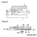
- Fig. 6 shows an example of a known disk device.
- Fig. 6 shows a disk tray 101 at the closed position, turntable 102, and a horizontal bar 104 supporting a clamp 103.
- the disk tray 101 moves in an arrow F direction from the closed position shown in the drawing and arrives at an open position that is not shown in the drawing.
- the disk tray 101 can also move in a direction opposite the arrow F direction from the open position and arrives at the closed position shown in the drawing.
- a disk D is loaded in a disk loading region Z1 formed as a concave receptacle on the disk tray 101.
- the disk loading region Z1 corresponding to a disk D of a large size, and a disk loading region Z2 corresponding to a disk (not shown in the drawing) of a small size and formed concentrically at the center position of the disk loading region Z 1 are formed in the disk tray 101 as shown Fig. 6. These two disk loading regions Z1 and Z2 are used in accordance with the size of the disk.
- the turntable 102 is positioned below the disk D loaded in the disk tray 101, which is moved from the open position to the closed position, such that when the turntable 102 is raised, the disk D loaded in the disk loading region Z1 (or disk loading region Z2) of the disk tray 101 is received by the turntable 102 and lifted from the disk tray 101.
- a clamp 103 disposed above the disk D overlaps the top surface of the disk D and operates its suction function such that the disk D is pressed against the turntable 102.
- the disk D is chucked by the turntable 102 and clamp 103 through this series of operations. Thereafter, when a recording or playing mode is selected, the turntable 102 rotates together with the disk D, and writing or reading is performed on the recording surface of the disk D by an optical pickup not shown in the drawing.
- the disk tray 101 is assembled to a frame body not shown in the drawing so as to be movable between the closed position and the open position.
- the horizontal bar 104 which is formed of resin, is formed unitarily with the frame body as a one-piece member.
- the direction of the arrow F is referred to as the frontward direction, while the direction opposite the arrow F is referred to as the rearward direction.
- a downward facing projection 141 is formed at a rear end portion of the horizontal bar 4, as shown in Fig. 6.
- this downward facing projection 141 contacts the peripheral edge of the disk D as indicated by the dashed lines in Fig. 6, such that the disk D is prevented from going behind the horizontal bar 104.
- the disk tray 201 is caused to move from the closed position shown in the drawing to the open position.
- the upward facing portions 212 fail to engage the peripheral edge of the disk D depending on the inclination of the disk D. Instead, the upward facing portions 212 slide in the F direction beneath the disk D as indicated by the dashed lines, with the result that the disk D cannot be ejected. In this case, not only is the disk D prevented from being ejected by due to the upward facing portions 212 locking the underside of the disk D, there is concern that the disk tray 201 may be jammed and may no longer open smoothly.
- An object of the present invention is to provide a disk device from which a disk can be retrieved smoothly.
- a disk is adapted to be loaded.
- the disk device includes a body structure; a disk tray supported by the body structure so as to be movable between a closed position and an open position, the disk tray including a base, a disk loading region which is adapted to receive the disk and is formed on the base, and an upward facing projection formed on the base on a closed position side of the disk loading region; and an upper case supported by the body structure and positioned above the disk loading region of the disk tray when the disk tray is at the closed position, the upper case including an upper ceiling portion, a downward facing projection formed on the upper ceiling portion so as to project downward, and an inclined surface formed between the upper ceiling portion and the downward facing projection so as to be inclined downward in a direction toward the closed position, the upward facing projection being positioned on the closed position side relative to the downward facing projection when the disk tray is at the closed position.
- the peripheral edge of a disk that has disengaged from the disk loading region of the disk tray is stopped by the bottom facing projection formed on the upper case, thus preventing the disk from shifting behind the upper case.
- the peripheral edge of the disk slides along the inclined surface provided on the downward facing projection, and is positioned opposite the upward facing projection formed on the disk tray side. Therefore, even when the disk disengages the disk loading region and becomes stuck at the downward facing projection, the upward facing projection engages at the peripheral edge of the disk and ejects the disk as the disk tray moves from the closed position to the open position.
- the upward facing projection be formed on the base so as not to reach the downward facing projection when the disk tray moves from the closed position to the open position. In this way, the smoothness of the disk tray movement is not compromised by the interference of the upward facing projection with the downward facing projection.
- the downward facing projection project downward from a bottom end portion of the inclined surface, a distance by which the downward facing projection extends downward beyond the bottom end portion of the inclined surface be designed to be smaller than a thickness of a peripheral edge of the disk, and a vertical distance between a bottom end of the downward facing projection and an upper end of the upward facing projection is smaller than a width of the peripheral edge of the disk that is exposed beneath the bottom end of the downward facing projection when the downward facing projection engages the disk. In this way, it is possible to prevent the upward facing projection from sliding beneath the disk or becoming stuck at the bottom side of the disk.
- the disk device further have a turntable arranged in the body structure below the disk loading region of the disk tray when the disk tray is at the closed position, the turntable being adapted to chuck the disk; and a clamp disposed above the turntable, the clamp being adapted to chuck the disk together with the turntable, the clamp being supported by the upper ceiling portion of the upper case.
- Fig. 1 is an external perspective view of the disk device in accordance with an embodiment of the invention
- Fig. 2 is a plan view of the disk device in accordance with the embodiment of the invention.
- Fig. 3 is a schematic side view of the disk device in accordance with the embodiment of the invention.
- Fig. 4 is a partial side view of the disk device in accordance with the embodiment of the invention.
- Fig. 5 is an enlarged view of the part V shown in Fig. 4;
- Fig. 6 illustrates an example of known disk device
- Fig. 7 illustrates another example of known disk device
- Fig. 8 illustrates the example of the known disk device of Fig. 7.
- Fig. 1 is an external perspective view briefly showing the disk device
- Fig. 2 is a plan view of the disk tray 1
- Fig. 3 is a schematic section view of the disk device of the first embodiment
- Fig. 4 is a partial exploded section view of the main parts of the first embodiment
- Fig. 5 is an enlargement of part indicated as V in Fig. 3.
- the disk device includes a body structure 100, a disk tray 1, a turntable 2, a clamp 3, and a horizontal bar 4 (an example of the upper case).
- the disk tray 1 is assembled in the body structure 100 that is formed of a resin body.
- the disk tray 1 is supported by the body structure 100 so as to be movable by a motor between a closed position within the body structure 100 and an open position outside the body structure 100.
- the disk tray 1 has a disk loading region Z 1 and a disk loading region Z2 that are concentrically formed and which receives the disk D.
- the horizontal bar 4 which is formed of resin, is formed unitarily with the body structure 100 as a one-piece structure, such that the horizontal bar 4 is positioned above the disk tray 1 when the disk tray 1 is at the closed position.
- the clamp 3 is supported by the horizontal bar 4 above the turntable 2.
- the turntable 2 is arranged in the body structure 100 to chuck the disk by working together with the clamp 3.
- the disk tray 1, the turntable 2, and the clamp 3 are operatively connected to a control unit that is not shown in Figures.
- the control unit selectively controls the operation of these components according to signals inputted by the user and operation programs stored therein. More specifically, the control unit preferably includes a microcomputer with a control program that controls the opening and closing operations of the disk tray 1 and the chucking operation of the turntable 2 and the clamp 3. Since these operations are well known in the art, details thereof will not be discussed or illustrated in detail herein.
- the horizontal bar 4 has a clamp support portion 43 (an example of the upper ceiling portion), and a downward facing projection 41 that is unitarily formed on the clamp support portion 43, such that the downward facing projection 41 stops the peripheral edge of a disk D that has disengaged from and has become misaligned relative to a disk loading region Z1 (or a disk loading region Z2) of the disk tray 1 at the closed position, so as to prevent the disk D from sliding toward the rear of the horizontal bar 4.
- a clamp support portion 43 an example of the upper ceiling portion
- a downward facing projection 41 that is unitarily formed on the clamp support portion 43, such that the downward facing projection 41 stops the peripheral edge of a disk D that has disengaged from and has become misaligned relative to a disk loading region Z1 (or a disk loading region Z2) of the disk tray 1 at the closed position, so as to prevent the disk D from sliding toward the rear of the horizontal bar 4.
- the disk tray 1 has a base 11, and a disk loading region Z1 for a large sized disk and a disk loading region Z2 for a disk (not shown in the drawing) of a small size disk that are concentrically formed at a center position in a concave receptacle shape on the base 11 of the disk tray 1.
- Upward facing projections 12 which are formed of resin are unitarily formed on the rear side (closed position side) of the disk loading regions Z1 and Z2. Since the upward facing projections 12 are formed short enough, they do not reach the downward facing projection 41 when the disk tray 1 is moved from the closed position to the open position.
- the horizontal bar 4 of the disk drive of the present embodiment is provided with a disk depressing guide surface 42 (an example of the inclined surface), which is inclined rearward and downward, between the downward facing projection 41 and the clamp support portion 43 of the horizontal bar 4.
- the disk depressing guide surface 42 pushes the peripheral edge of the disk D that has disengaged from the disk loading position Z1 (or disk loading position Z2) and shifted rearward, such that the disk D slides rearward along the disk depressing guide surface 42 and project from the bottom end 41a of the downward facing projection 41.
- the disk D is positioned opposite the upward facing projections 12, which are formed on the disk tray 1 on the rear side (closed position side) relative to the downward facing projection 41, as shown in Fig. 5.
- the downward facing projection 41 is formed so as to project from the rear bottom end 42a of the disk depressing guide surface 42.
- the distance a by which the downward facing projection 41 extends downward beyond the rear bottom end 42a of the disk depressing guide surface 42 is shorter than the thickness t of the peripheral edge of the disk D, and the vertical distance b between the bottom end 41a of the downward facing projection 41 and the upper surfaces of the upward facing projections 12 are shorter than the distance c by which the peripheral edge of the disk D is exposed beneath the bottom end 41 a of the downward facing projection 41 when the downward facing projection 41 engages the disk D.
- a disk device of the above described configuration even when the disk D becomes disengaged from the disk loading region Z1 (or disk loading position Z2) of the disk tray 1 that is at the closed position, the peripheral edge of the disk D is stopped by the downward facing projection 41 of the horizontal bar 4. Thus, the disk D is prevented from sliding behind the horizontal bar 4, as shown in Figs. 4 and 5. Furthermore, since the peripheral edge of the disk D is stopped by the upward facing projections 12 formed on the disk tray 1, even if the disk D slides past the downward facing projection 41 by chance, the disk D can still be prevented from sliding behind the horizontal bar 4. Accordingly, the situation in which the disk D cannot be removed unless the disk device is broken apart to remove the disk tray 1 from the body structure 100 is less likely to occur.
- the state in which the peripheral edge of the disk D is stopped by the downward facing projection 41 of the horizontal bar 4 occurs when the peripheral edge of the disk D slides backward along the disk depressing guide surface 42. Therefore, a part of the peripheral edge of the disk D stopped by the downward facing projection 41 extends below the bottom end 41 a of the downward facing projection 41 by the exposed width dimension c, and is positioned opposite the upward facing projections 12 in the horizontal direction (direction of the movement of the disk tray 1).
- the upward facing projections 12 stop at the peripheral edge surface of the disk D as indicated by the dashed line 12 in Fig. 5, and the disk D is ejected from the body structure 100 by the disk tray 1.
- the upward facing projections 12 pass under the downward facing projection 41 without interfering with the downward facing projection 41. Accordingly, the situation in which the upward facing projections 12 interfere with the downward facing projection 41 causing loss of smooth movement of the disk tray 1 can be prevented.
Landscapes
- Feeding And Guiding Record Carriers (AREA)
- Holding Or Fastening Of Disk On Rotational Shaft (AREA)
Applications Claiming Priority (1)
| Application Number | Priority Date | Filing Date | Title |
|---|---|---|---|
| JP2005007492A JP3937353B2 (ja) | 2005-01-14 | 2005-01-14 | ディスク装置 |
Publications (3)
| Publication Number | Publication Date |
|---|---|
| EP1684285A2 true EP1684285A2 (de) | 2006-07-26 |
| EP1684285A3 EP1684285A3 (de) | 2008-11-12 |
| EP1684285B1 EP1684285B1 (de) | 2011-07-27 |
Family
ID=35841744
Family Applications (1)
| Application Number | Title | Priority Date | Filing Date |
|---|---|---|---|
| EP06000044A Expired - Lifetime EP1684285B1 (de) | 2005-01-14 | 2006-01-02 | Plattenvorrichtung |
Country Status (4)
| Country | Link |
|---|---|
| US (1) | US7516461B2 (de) |
| EP (1) | EP1684285B1 (de) |
| JP (1) | JP3937353B2 (de) |
| CN (1) | CN100481230C (de) |
Citations (1)
| Publication number | Priority date | Publication date | Assignee | Title |
|---|---|---|---|---|
| EP0561350A2 (de) | 1992-03-19 | 1993-09-22 | Sony Corporation | Plattenladegerät |
Family Cites Families (11)
| Publication number | Priority date | Publication date | Assignee | Title |
|---|---|---|---|---|
| JPS6050748A (ja) * | 1983-08-31 | 1985-03-20 | Toshiba Corp | 光学式デイスクレコ−ド再生装置 |
| JP2924334B2 (ja) | 1991-08-09 | 1999-07-26 | 松下電器産業株式会社 | ディスクプレーヤ |
| JPH11134758A (ja) | 1997-10-28 | 1999-05-21 | Ricoh Co Ltd | 光ディスクドライブ装置 |
| JP2001021155A (ja) | 1999-07-08 | 2001-01-26 | Sanyo Electric Co Ltd | 加熱調理器 |
| JP4196514B2 (ja) * | 2000-02-08 | 2008-12-17 | ミツミ電機株式会社 | ディスク装置 |
| JP2001222847A (ja) | 2000-02-08 | 2001-08-17 | Mitsumi Electric Co Ltd | ディスク装置 |
| JP2002184071A (ja) * | 2000-12-11 | 2002-06-28 | Kenwood Corp | ディスク搬送装置 |
| JP2002352499A (ja) * | 2001-05-23 | 2002-12-06 | Victor Co Of Japan Ltd | ディスク駆動装置 |
| JP2003022599A (ja) | 2001-07-04 | 2003-01-24 | Kenwood Corp | ディスクドライブ装置 |
| JP2004145912A (ja) | 2002-10-21 | 2004-05-20 | Pioneer Electronic Corp | 記録媒体再生装置 |
| TWM251256U (en) * | 2003-12-29 | 2004-11-21 | Benq Corp | Disc accessing apparatus and the panel thereof |
-
2005
- 2005-01-14 JP JP2005007492A patent/JP3937353B2/ja not_active Expired - Fee Related
-
2006
- 2006-01-02 EP EP06000044A patent/EP1684285B1/de not_active Expired - Lifetime
- 2006-01-12 CN CNB200610000936XA patent/CN100481230C/zh not_active Expired - Fee Related
- 2006-01-13 US US11/331,046 patent/US7516461B2/en not_active Expired - Fee Related
Patent Citations (1)
| Publication number | Priority date | Publication date | Assignee | Title |
|---|---|---|---|---|
| EP0561350A2 (de) | 1992-03-19 | 1993-09-22 | Sony Corporation | Plattenladegerät |
Also Published As
| Publication number | Publication date |
|---|---|
| EP1684285A3 (de) | 2008-11-12 |
| JP2006196103A (ja) | 2006-07-27 |
| JP3937353B2 (ja) | 2007-06-27 |
| CN1811946A (zh) | 2006-08-02 |
| US20060161930A1 (en) | 2006-07-20 |
| CN100481230C (zh) | 2009-04-22 |
| EP1684285B1 (de) | 2011-07-27 |
| US7516461B2 (en) | 2009-04-07 |
Similar Documents
| Publication | Publication Date | Title |
|---|---|---|
| US5923509A (en) | Disk cartridge with judging recesses | |
| JP5577678B2 (ja) | カートリッジドライブ装置 | |
| KR101783046B1 (ko) | 디스크 카트리지 | |
| US6934957B2 (en) | Recording medium driving device | |
| US5204853A (en) | Adaptor for a disc cartridge case | |
| US6751180B2 (en) | Disk player | |
| JP3890660B2 (ja) | ディスク記録及び/又は再生装置 | |
| JP3890661B2 (ja) | ディスク記録及び/又は再生装置 | |
| KR100538022B1 (ko) | 디스크장치 | |
| US7516461B2 (en) | Disk device | |
| KR100615996B1 (ko) | 디스크장치 | |
| JP3757532B2 (ja) | ディスク記録及び/又は再生装置 | |
| EP1087391A1 (de) | Platteneinheit | |
| JP2007157190A (ja) | ディスクドライブ装置 | |
| US7337449B2 (en) | Disk drive for minimizing jamming during disk positioning | |
| JP5445055B2 (ja) | ディスクカートリッジ | |
| JP3807279B2 (ja) | ディスク装置 | |
| JP3890659B2 (ja) | ディスク記録及び/又は再生装置 | |
| JP3757533B2 (ja) | ディスク記録及び/又は再生装置 | |
| JP3891216B2 (ja) | ディスク記録及び/又は再生装置 | |
| US20070124742A1 (en) | Disk device having ribs for preventing fall-in of disk medium | |
| JP5141179B2 (ja) | ディスク装置 | |
| JP2007157189A (ja) | ディスクドライブ装置 | |
| US20050201216A1 (en) | Recording medium driving device | |
| JP2010067303A (ja) | ディスクドライブ装置及び電子機器 |
Legal Events
| Date | Code | Title | Description |
|---|---|---|---|
| PUAI | Public reference made under article 153(3) epc to a published international application that has entered the european phase |
Free format text: ORIGINAL CODE: 0009012 |
|
| AK | Designated contracting states |
Kind code of ref document: A2 Designated state(s): AT BE BG CH CY CZ DE DK EE ES FI FR GB GR HU IE IS IT LI LT LU LV MC NL PL PT RO SE SI SK TR |
|
| AX | Request for extension of the european patent |
Extension state: AL BA HR MK YU |
|
| PUAL | Search report despatched |
Free format text: ORIGINAL CODE: 0009013 |
|
| AK | Designated contracting states |
Kind code of ref document: A3 Designated state(s): AT BE BG CH CY CZ DE DK EE ES FI FR GB GR HU IE IS IT LI LT LU LV MC NL PL PT RO SE SI SK TR |
|
| AX | Request for extension of the european patent |
Extension state: AL BA HR MK YU |
|
| 17P | Request for examination filed |
Effective date: 20090310 |
|
| AKX | Designation fees paid |
Designated state(s): DE FR GB |
|
| 17Q | First examination report despatched |
Effective date: 20090917 |
|
| GRAP | Despatch of communication of intention to grant a patent |
Free format text: ORIGINAL CODE: EPIDOSNIGR1 |
|
| GRAS | Grant fee paid |
Free format text: ORIGINAL CODE: EPIDOSNIGR3 |
|
| GRAA | (expected) grant |
Free format text: ORIGINAL CODE: 0009210 |
|
| AK | Designated contracting states |
Kind code of ref document: B1 Designated state(s): DE FR GB |
|
| REG | Reference to a national code |
Ref country code: GB Ref legal event code: FG4D |
|
| REG | Reference to a national code |
Ref country code: DE Ref legal event code: R096 Ref document number: 602006023246 Country of ref document: DE Effective date: 20110915 |
|
| PLBE | No opposition filed within time limit |
Free format text: ORIGINAL CODE: 0009261 |
|
| STAA | Information on the status of an ep patent application or granted ep patent |
Free format text: STATUS: NO OPPOSITION FILED WITHIN TIME LIMIT |
|
| 26N | No opposition filed |
Effective date: 20120502 |
|
| REG | Reference to a national code |
Ref country code: DE Ref legal event code: R097 Ref document number: 602006023246 Country of ref document: DE Effective date: 20120502 |
|
| REG | Reference to a national code |
Ref country code: FR Ref legal event code: PLFP Year of fee payment: 11 |
|
| PGFP | Annual fee paid to national office [announced via postgrant information from national office to epo] |
Ref country code: GB Payment date: 20151230 Year of fee payment: 11 |
|
| PGFP | Annual fee paid to national office [announced via postgrant information from national office to epo] |
Ref country code: FR Payment date: 20151208 Year of fee payment: 11 |
|
| PGFP | Annual fee paid to national office [announced via postgrant information from national office to epo] |
Ref country code: DE Payment date: 20151229 Year of fee payment: 11 |
|
| REG | Reference to a national code |
Ref country code: DE Ref legal event code: R119 Ref document number: 602006023246 Country of ref document: DE |
|
| GBPC | Gb: european patent ceased through non-payment of renewal fee |
Effective date: 20170102 |
|
| REG | Reference to a national code |
Ref country code: FR Ref legal event code: ST Effective date: 20170929 |
|
| PG25 | Lapsed in a contracting state [announced via postgrant information from national office to epo] |
Ref country code: FR Free format text: LAPSE BECAUSE OF NON-PAYMENT OF DUE FEES Effective date: 20170131 |
|
| PG25 | Lapsed in a contracting state [announced via postgrant information from national office to epo] |
Ref country code: GB Free format text: LAPSE BECAUSE OF NON-PAYMENT OF DUE FEES Effective date: 20170102 Ref country code: DE Free format text: LAPSE BECAUSE OF NON-PAYMENT OF DUE FEES Effective date: 20170801 |